 Bud Bennett
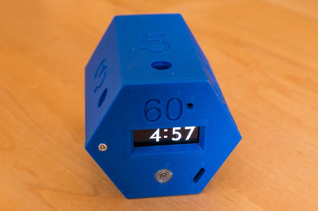
The battery spring contacts, 9x4.2mm passive buzzers and LED windows arrived a couple of days ago. I was able to test out the battery holder concept and the fit/finish of the case. Here's what I have right now:
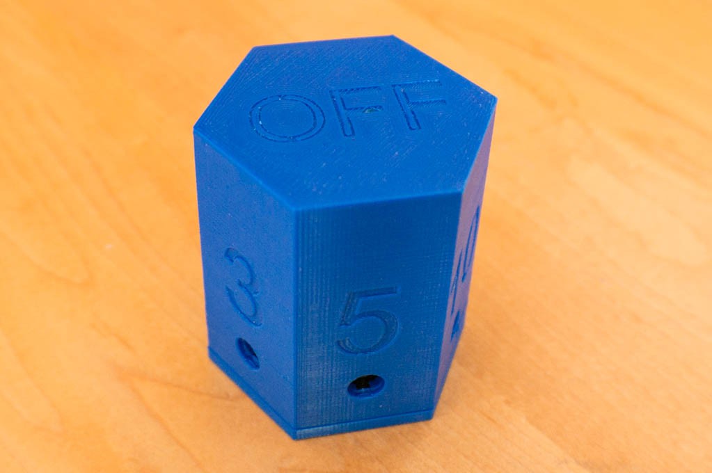
There is a single M1.7x6mm screw holding the top to the case bottom. I couldn't figure out how to make it secure with spring-loaded plastic catches -- they kept breaking.
The battery holder scheme seems to work well. It is a bit difficult to install the spring clip at the bottom of the case. I used a battery to hold it in place while dripping CA glue onto the spring clip and inadvertently glued the battery into the holder. The PIC doesn't always run properly if there is intermittent power application while setting the PCB over the positive battery terminal. This should resolve itself when the watchdog overflows after about 5 minutes -- I'll have to test that.
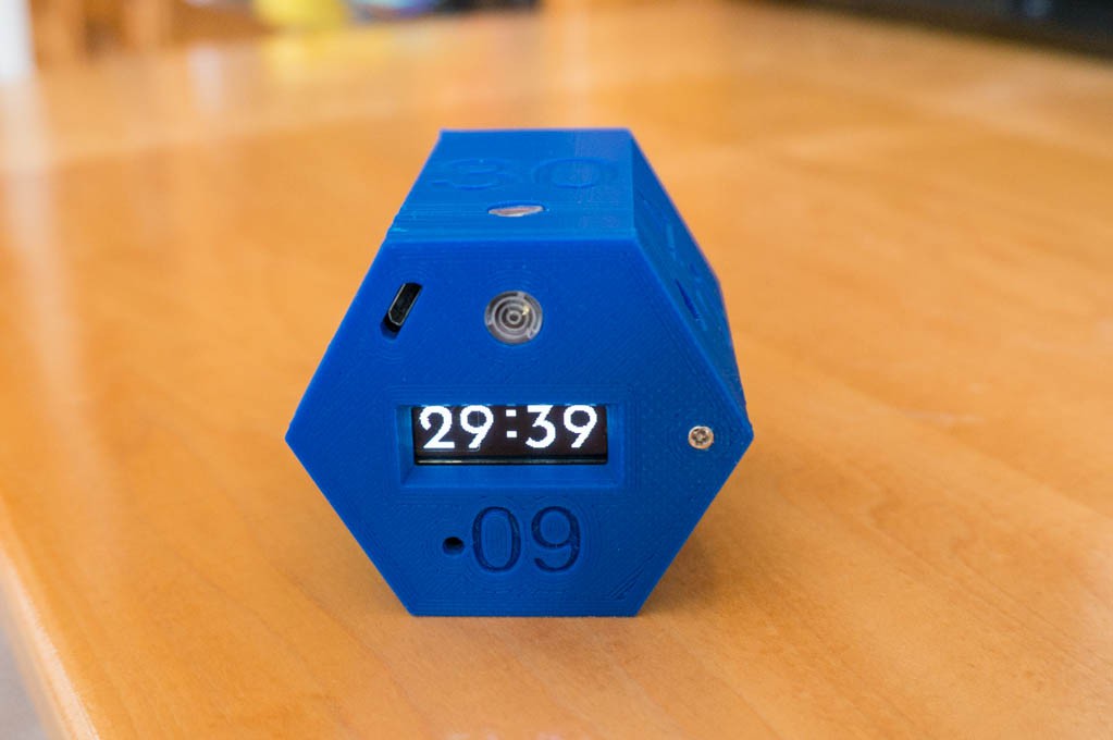
The USB charging port hole still needs some relocation to center it better over the connector. Note that the display inverts for the 15/30/45 minute hemisphere so that it is still readable. I have also implemented rudimentary versions of the start beep, end beep, and off beep. The end beep is two recurring short tones that start out quietly (5% duty cycle) and grow with each successive pair of beeps until the box is flipped to a new position or "Off". The end beep series is 30 pairs, which should give the user plenty of notice.
Still Plenty Left to Do:
- Implement LED indicators.
- Fine tune the accelerometer parameters for initial position sensing interrupt trigger.
- Fine tune the accelerometer parameters for each timer position to avoid false triggers or changes from noise or small disturbances upon the resting surface.
- Implement the low battery indicator and charging indicator.
- Reduce the thickness of the bezel around the display. The 60 degree bezel doesn't allow the entire display to be viewed at an angle. This should be relatively easy to accomplish by just using the header spacers included with the OLED boards to increase the height of the OLED from the PCB surface.
- Stuff that I haven't thought of yet.
Discussions
Become a Hackaday.io Member
Create an account to leave a comment. Already have an account? Log In.