 Guillermo Perez Guillen
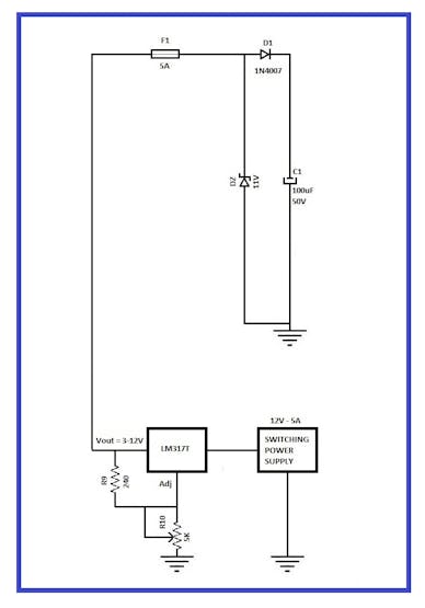
Circuit diagram of the power supply
How does it work?
a) The switching power supply provides a stable voltage of 12 Volts DC, 5 Amps and a maximum power of 330 watts. With this device, we will find good stability of the system and we have to adjust the voltage load with which we want to charge our battery and using a potentiometer (R10). We can consult international standards here: https://standards.ieee.org/standard/765-2012.html
b) The integrated circuit LM317 was used to generate a voltage regulated from 3 to 12 volts by means of potentiometer R10. The technical specifications of this integrated say that it can´t generate less than 3 volts. In this example, I adjust 5.6 volts. The calculations are:
In the technical sheet of LM317 we find the following formula:
Vout =Vref [1+(R2/R1)] +(iADJ)(R2)
For example, the maximum voltage that the LM317can works is 37 Volts, and if in our diagram we take R9 as 240 ohms, then we do the calculation for R10.
Vout =Vref [1+(R10/R9)] +(iADJ)(R10)
We consider a very small value of iADJ, and if we calculate R10, we would have:
R10 = (R9/Vref) (Vout -Vref)
R10 = (R9/1, 2) (Vout - 1, 2)
R10 =(240/1, 2)(37-1, 2) = 7, 160 ohms
And for practical uses, we use a 10k potentiometer.
c) The Zener diode DZ serves as a voltage regulator and at it´s output I obtained a maximum of 10.8 volts, which I measured with a voltmeter.
d) The protection devices used are the following: Fuse F1, Capacitor C1 and Diode D1. These elements are very important to protect the system against short circuits, discharges, elimination of reverse direct currents and filter against unwanted signals.
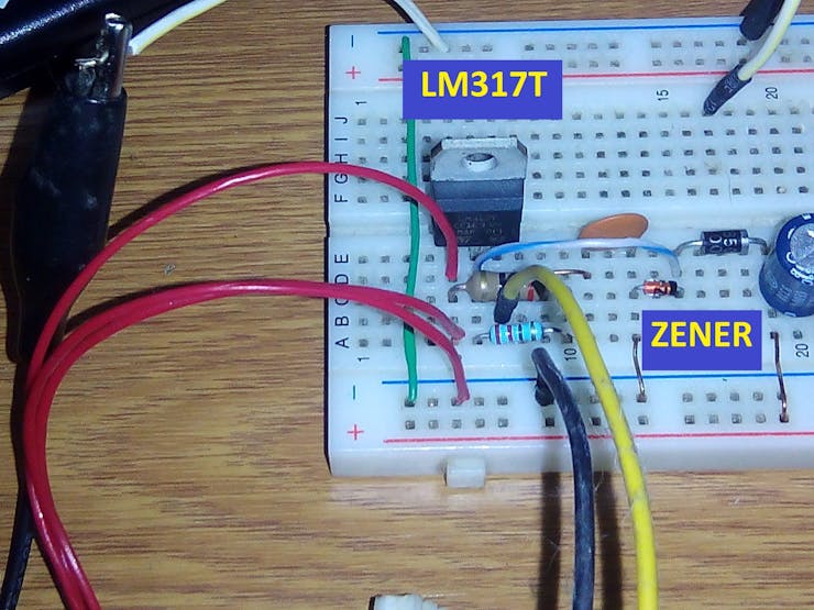
Be careful with the connections of the LM317T regulator and the Zener diode
Discussions
Become a Hackaday.io Member
Create an account to leave a comment. Already have an account? Log In.