 zpekic
The calculator/CPU cannot function on its own, without being embedded in a system that gives it the I/O, clock, outside hardware connections etc. on the FPGA board.
The top-level object that does this is sys_sbc8816.vhd
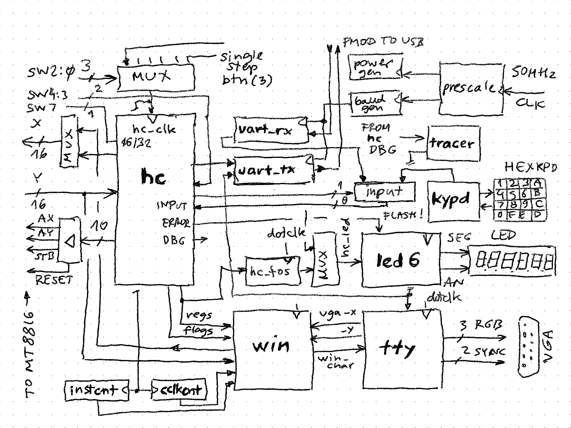
(simplified schema, bolded names correspond to components in the source code)
Why is this so complicated? The reason is that lots of debugging components have been added to the design:
- win - this allows generating a "hardware window" that shows all the 256 switch states (which are in external MT8816 chips), as well as the state of CPU regs and flags
- tty - allows CPU to "write" top of stack, errors etc. to VGA
- tracer - allows showing (part of) microcode as being executed
- uart_rx and uart_tx - commands to CPU can come from USB serial, and microcode tracing and/or result display can go to USB too - so a terminal app can be used to interact
For the basic operation of the calculator, only 3 components are needed:
- hc - the calculator itself with its hardware connections to MT8816s
- kypd - allows entry of 0-F digits and all the commands (button(3) + digit == command)
- led6 - displays TOS (top of stack) to 6 7-segment LEDs (too bad Anvyl doesn't have 8 of these for full 32-bits, I didn't bother installing the "scrolling" of 6 digit window of 8 digit display yet)
Clock generation
All clocks derive from 100MHz clock integrated on the Anvyl board. From this, 3 separate paths are taken:
- Simple division by two (signal freq_50M) used by VGA (25MHz dot frequency for 640*480) and further down for CPU and other places
- Pre-scaling to generate 2^n frequency, which goes down to 1Hz eventually (signal freq_2048)
- Pre-scaling to generate baudrates - switches on board select a divide value from prescale_lookup table for UART send and recive (typically 38400bps)
CPU clock is selectable using switches 2..0. 0 selects single step (useful for much painful debugging), and 7 is full-speed. In addition speeds 0..3 enable tracing the microcode.
-- select the clock
with sw_clksel select mt_cnt <=
    ss_cnt    when "000",    -- single step
    freq_2048(9 downto 8) when "001",    -- 4Hz
    freq_2048(7 downto 6) when "010",    -- 16Hz
    freq_2048(5 downto 4) when "011",    -- 64Hz
    freq_50M(8 downto 7) when "100",        -- 0.195312
    freq_50M(7 downto 6) when "101",        -- 0.390625
    freq_50M(6 downto 5) when "110",        -- 0.781250
    freq_50M(5 downto 4) when others;    -- 1.5625MHz

-- 4 phase clock to activate strobe at right time
phi0 <= '1' when (mt_cnt = "00") else '0';
phi1 <= '1' when (mt_cnt = "01") else '0';
phi2 <= '1' when (mt_cnt = "10") else '0';
phi3 <= '1' when (mt_cnt = "11") else '0';

-- single step cnt
on_button3: process(button(3), ss_cnt)
begin
    if (rising_edge(button(3))) then
        ss_cnt <= std_logic_vector(unsigned(ss_cnt) + 1);
    end if;
end process;
MT8816 control signals have some requirement of setup and hold times before/after STB, so these are achieved by using a 4-phase clock, and activating control signals at their duty cycle.
Instruction input
The CPU / calculator executes instructions which are 8-bit ASCII character code. These characters can come from:
- 16-key hex keypad. The state of button(3) is appended to 4-bit generated by this keyboard to lookup the ASCII code in a 32*8 bit ROM
- UART RX, connected to PMOD and USB - this way a host machine keyboard can be used
Both of these generate a strobe pulse, and first one received wins, loading the ASCII value into input register. This is actually the "instruction register" of the CPU. This register holds the character until CPU clears it (instruction is executed).
key <= rx_ready or kypd_keypressed;
input_clear <= '1' when (hc_status = status_done) else reset;

on_key: process(key, kypd_hex, kypd_shift, rx_char, input_clear)
begin
    if (input_clear = '1') then
        input <= X"00";
    else
        if (rising_edge(key)) then
            if (kypd_keypressed = '1') then
                input <= kypd2ascii(to_integer(unsigned(kypd_shift & kypd_hex)));
            else
                input <= rx_char;
            end if;
        end if;
    end if;
end process;
Inside the microcode there is simple loop waiting until input register !=0, meaning new character has been received. The input register could be replaced with a FIFO queue.
//    indicate availability and wait for start signal
//    ---------------------------------------------------------------------------
deadloop:    STATUS = ready, if input_is_zero then repeat else next;
        echo(input);
        if true then fork else fork;    // jump to entry point per character code (see .map statements below)
Serial text output path
Two components can generate a stream of text (lines + CR + LF sequence):
- CPU can echo the input char processed if "trace input" (switch(4)) is turned on, and also print TOS if "trace result" (switch(3)) is turned on. Error number (and input) is also always streamed out in case of error
- Tracer can generate a line containing some select data and part of microinstruction address and source code
Two components can handle these stream:
- TTY - "prints" the stream to 80*60 character RAM which is then displayed on VGA. The description of this component is here, but for this design it is expanded to handle the character coming from "hardware window"
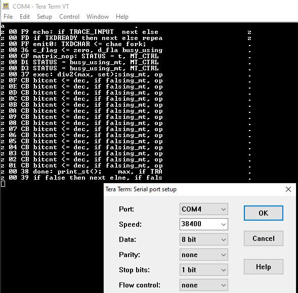
- UART TX - connected to PMOD and then USB to display it on terminal window as seen above
Which source goes to which destination can be selected with switch(6..5)
Visualizing CPU state
It is very useful for debugging and also to explain the concept to see the internals of the CPU, as execution is unfolding. There are few problems:
- 16*16 switch matrix is "logically" inside the CPU but physically it is outside. This is solved by "hardware window" component generating the row activation signals for MT8816 when CPU is not using it, one screen row at the time, and as column is known too, pick up the on/off state in X/Y matrix
- There is lots of registers inside the CPU - 8 32-bit general purpose, 16-bit zero flags, C, D, A flags. To avoid excessive connections, a multiplexing approach is used. The window is 32*32 and each of these 1024 location is described by a mask that selects a particular input, and then passes it through binary to ASCII or hex to ASCII lookup tables.
-- hardware window that shows the system state
win: hardwin Port map(
        left => X"18", -- col 24, TODO make it dynamic
        top  => X"10",    -- row 16, TODO make it dynamic
        vga_x => vga_x,
        vga_y => vga_y,
        active => win_active,
        matrix => win_matrix,
        char     => win_char,
        index     => win_index,
        win_x  => win_x,
        win_y  => win_y,
        sy_cnt => sy_cnt,
        switch => switch, -- display the modes in the last row of the window
        mt_x   => hc_mt_x(to_integer(unsigned(win_y(3 downto 0)))),
        mt_y   => mt_y(to_integer(unsigned(win_x(3 downto 0)))),
        mt_c     => hc_carry,
        mt_d     => hc_delay,
        mt_daa => hc_daa,
        mt_z     => hc_zero(to_integer(unsigned(win_y(3 downto 0)))),
        mt_hex => hc_reg
        );
The key are values vga_x (0 to 79) and vga_y (0 to 59) that are generated by VGA controller. If these values fall within the 32*32 where the window is positioned (note the "top, left" offset of origin), win_active is '1' and win_x and win_y are valid - these are fed to CPU to extract a particular value from the register (e.g. 1 : 7 means least significant nibble from register 1). The hardwin component then internally generates ASCII representation which is output as win_char. If it is !=0, this character takes precedence over the one on same location in video RAM, so it appears that window floats above scrollable text screen.
The win_char is externally overriden in 16-bit mode and for the first 4 columns of the window to 0x00, meaning that it will be "chopped off" to hide upper 16-bits of the 8 registers:
-- if in 16-bit mode, simply chop off first four columns from hardware window (register bits 31..16)
win_char_x <= X"00" when ((sw_32 = '0') and (win_x(4 downto 2) = "000")) else win_char;
To show TOS on the 7-segment LED as an old fashioned calculator should, the hc_reg value should be intercepted at the right time, when win_y (row) is 0 and win_x (column) is 0...7, except 0 is most significant nibble, 7 least (only 2 to 7 are needed as the board has only 6 LEDs not 8). At those right moments, the values are captured into hc_tos display register which feeds the 7-seg using the led6:sixdigitsevensegmentled component in a standard multiplexed fashion.
-- catch stacktop appearing to display it on the 7seg LED
on_dot_clk: process(dot_clk, win_x, win_y, hc_reg)
begin
    if (rising_edge(dot_clk)) then
        if (win_y = "00000") then
            case win_x is
                when "00010" =>
                    hc_tos(23 downto 20) <= hc_reg;
                when "00011" =>
                    hc_tos(19 downto 16) <= hc_reg;
                when "00100" =>
                    hc_tos(15 downto 12) <= hc_reg;
                when "00101" =>
                    hc_tos(11 downto 8) <= hc_reg;
                when "00110" =>
                    hc_tos(7 downto 4) <= hc_reg;
                when "00111" =>
                    hc_tos(3 downto 0) <= hc_reg;
                when others =>
                    null;
            end case;
        end if;
    end if;
end process;
Discussions
Become a Hackaday.io Member
Create an account to leave a comment. Already have an account? Log In.