The raw PCM signal on Pin 11 is ugly. The unfiltered "carrier wave" causes loud ultrasonic noise at 62.5 kHz (and 187.5 kHz and so on). This is just over a decade above the 4 kHz Nyquist frequency so to reduce the noise by 40dB you need a second-order low-pass filter. The time-honored approach here is to say "the speaker's inductance makes it an OK first-stage low-pass filter and the human ear will do as the second stage". For many purposes this might be true. However, even if you can't directly hear the ultrasonic noise, it interferes with the speakers ability to produce fidelitous sound.
The raw signal also has much too high impedance to drive a speaker (typically 8 to 32 Ω). To kill two birds with one stone I therefore decided to use a Sallen-Key (second-order active) low-pass filter with a cut-off frequency of 4 kHz. The generic Sallen-Key topology uses an opamp with the output directly connected to the inverting input. I've always wanted to try to use a slightly less ideal gain device for this purpose: a single-BJT emitter follower. The emitter then becomes the inverting input / output and the base corresponds to the non-inverting input. Here's the schematic:
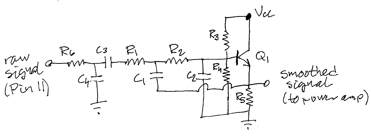
The Sallen-Key filter consists of Q1, R1-R5 and C1-C2. To the left of the coupling cap C3 there's a passive filter (R6 and C4) that I'll probably get rid of in the next version. Q1 is an 2SC1815 NPN BJT, chosen because it has the highest gain (β ≈ 700) of the transistors I had at hand. Values of the passives are chosen to implement a Chebyshev low-pass filter with cut-off frequency 4 kHz and 1dB passband ripple: R1 = R2 = 4.7 kΩ, C1 = 22 nF and C2 = 4.7 nF. The voltage divider used for biasing has resistor values R3 = 3 kΩ and R4 = 4.7 kΩ, respectively. The emitter resistor R5 = 2.2 kΩ. The coupling cap C3 = 10 μF and for a passive low-pass filter cut-off frequency of 4 kHz, R6 = 4 kΩ and C4 = 10 nF were chosen. VCC is the regulated 5 V from the Arduino Uno clone. I don't use the Arduino IDE, so don't shame me for buying clones.
Here's the circuit on a half-finished perfboard "shield":
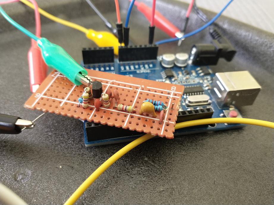
For C1 i used two 10 nF caps (I'm out of 22 nF) and for R6 I for some reason used (2.2 + 2) kΩ (a 3.9 kΩ resistor would have been fine). The circuit underwent some tinkering on a breadboard on my desk last fall and my notes are not exactly complete, but I remember that I was satisfied that the filter was reasonably optimized when I put it on the back burner. I recently migrated the circuit to perfboard without making any other changes.
Here's what it does with an 8-bit, 1-kHz sine wave from Pin 11:
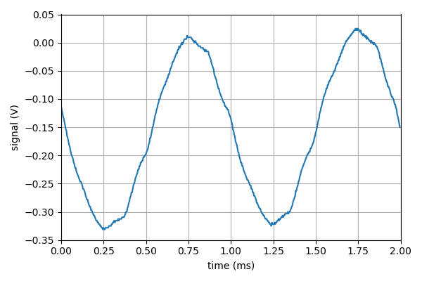
Not a perfect sine wave, but at least the distortion is symmetric. Here's an FFT of the same signal:
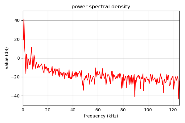
The strongest harmonic is the 7th one, 30dB below the fundamental, the 3rd and 9th are about 36dB below. The even harmonics are weak, consistent with the symmetric distortion. Whatever is left of the carrier wave at 62.5 kHz is suppressed by at least 50dB, which is probably more than needed, but I will test that hypothesis at some point.
Discussions
Become a Hackaday.io Member
Create an account to leave a comment. Already have an account? Log In.