The raudio format
The format of the audio played back is very simple, as it has to be to be unpacked in the interrupt handler on a low-end MCU. Bit crushing is done by using a single byte (a variable of type unsigned char) to store 2, 4 or 8 audio samples. For example, here's a complete raudio file called sine1kHz4b.h:
/* Single-period 1 kHz sine wave (w/ 4 bits per sample), made by hand */

#ifndef RAUDIO_PREFIX
#define RAUDIO_PREFIX
#endif

#define KONK(a, b) KONK_(a, b)
#define KONK_(a, b) a ## b

const unsigned char KONK(RAUDIO_PREFIX, raudio_bitdepth) = 4;
const unsigned int KONK(RAUDIO_PREFIX, raudio_length) = 4;

const unsigned char KONK(RAUDIO_PREFIX, raudio_data)[] PROGMEM = {216, 223, 56, 49};
/* {255, 255, 17, 17}; */  /* square wave (for debugging) */
There are some ugly preprocessor macros that allow you to add a prefix to the default variable names (raudio_bitdepth, raudio_length and raudio_data). KONK is short for konkatenera (Swedish for concatenate). The audio samples are stored in the array raudio_data. The eight 4-bit samples that define one period of a sine wave are {8, 13, 15, 13, 8, 3, 1, 3}. These are pairwise stuffed into a single byte: for {8, 13} we get 8+ 16 x 13 = 216, et cetera. The sample values can then be quickly unpacked by some bit twiddling in the interrupt handler (ISR):
if (!nsample) databyte = pgm_read_byte(raudio_data + nbyte++);
OCR1A = (databyte >> (nsample << 2)) & 15;
nsample = ++nsample % 2;
OCR1A is the register that determines the duty cycle of the PWM carrier wave. The byte counter nbyte is incremented every time a new byte of raudio data is loaded from flash. Its type is now an unsigned int, which takes up two bytes with avr-gcc, the same as memory pointers. For a while I used a four-byte integer type (unsigned long) for a sample counter, but since it's used for pointer arithmetic it is less bug-prone to use pointers that won't overflow memory addresses so easily. The two-byte counter is supplemented by a single-byte (unsigned char) sample counter nsample that counts the samples within a byte. The code snippet above is for four-bit audio, with the first sample (nsample == 0) stored in the low four bits of the byte, and the second sample (nsample == 1) stored in the high four bits. So for the first sample we just have to use the mask decimal 15 (equals binary 1111) to zero out the four high bits. For the second sample we first have to shift the bits four (nsample << 2) positions to the right. The PWM counter is running at 64 MHz and the PWM period is 256 counts for 8-bit raudio, 16 counts for 4-bit, 4 counts for 2-bit and 2 counts for 1-bit.
The interrupt handler is called with a frequency of fS = 8 kHz (every 125 us) so even at 1 MHz system clock there is ample time to perform the operations needed. There's 125 cycles between interrupts, minus overhead and cycles spent servicing the intrinsic PWM interrupts. Most (or all?) of the operations should be single-cycle ones, so there's plenty of headroom.
The tools sox and wav2h can be used to convert an mp3 file into an approriate wav file (single channel, 8 kHz, 8 bit) and convert the wav to raudio, respectively. I'm currently migrating away from wav2h to python so that I can use scipy to do some audio processing.
Measured output signals
Below are the measured signals with just a first-order low-pass filter (R = 390 Ω, C = 100 nF) and a coupling cap (C = 10 μF) in the signal path between the tn85 output pin and the 'scope. First, for 8-bit raudio the output signal looks like this:
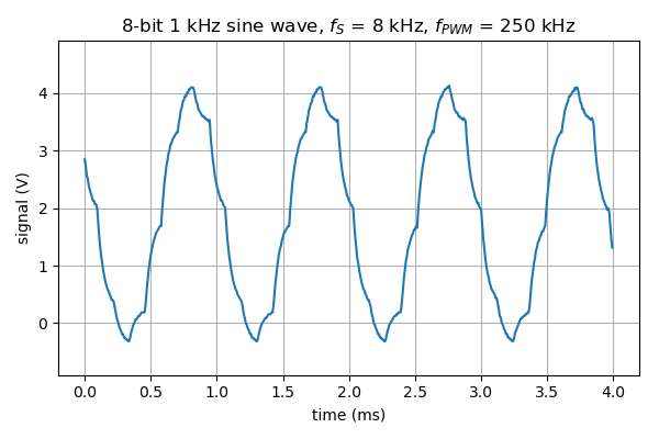
The carrier frequency fPWM = 64 MHz / 256 counts = 250 kHz.
Next, 4-bit raudio:
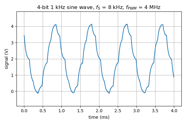
The carrier frequency fPWM = 64 MHz / 16 counts = 4 MHz.
2-bit raudio:
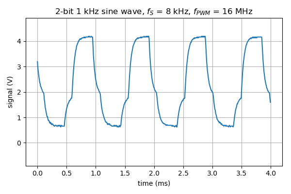
The carrier frequency fPWM = 64 MHz / 4 counts = 16 MHz.
Finally, for 1-bit raudio:
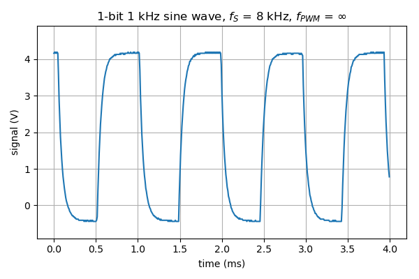
One would think that the carrier frequency fPWM = 64 MHz / 2 counts = 32 MHz, but for Timer 1 on ATtiny85 setting the clear-on-compare-match value (register OCR1C) to zero makes the duty cycle exactly zero, i.e. the PWM output stays low making the PWM frequency effectively infinite. You still want a low-pass filter though, to suppress the harmonics of the sample frequency fS, caused by the amplitude discretization error.
Discussions
Become a Hackaday.io Member
Create an account to leave a comment. Already have an account? Log In.