TL;DR
I'm proposing a minimalist Class AB power amp to drive an 8-Ohm speaker with AVR PCM audio as input. It uses two heatsinked TO-92 complementary BJTs and puts a quarter of a watt into an 8-Ohm load (the loudspeaker). Distortion is low for an 8-Ohm speaker, but noticeable for a 4-Ohm one. In my opinion it represents a local maximum for performance as a function of complexity. Here's the schematic:
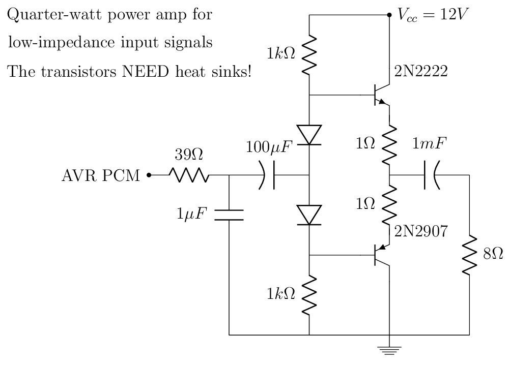
My version of circuitikz doesn't have a loudspeaker symbol, so you have to imagine the 8-Ohm resistor to be one. Nothing really new about this schematic, of course. You'll find very similar ones in AoE, for example. It does take full advantage of the nicely loud and thick (low-impedance) output signal from ATmega328p and ATtiny85.
The scenic route
My old plan for a power amp Mk2 version for this project was a Class B with negative feedback to fix the crossover distortion (inspired by some Soviet toy-synth schematics). So a two-stage power amp with complementary TO-220 BJTs in the output stage feeding back the output signal to the preceding voltage-gain stage. As I was happily spicing away, it occurred to me that the PCM signal might just have low enough impedance and high enough amplitude to allow a power amp stripped down to just an output stage.
The ATmega328p datasheet does have graphs for output pin DC voltage vs. current at various temperatures:
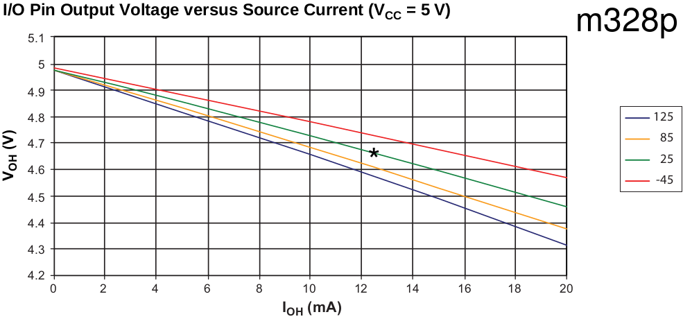
So at room temperature (25C, the green graph), drawing 12.5 mA reduces the voltage on the output pin to 4.67 V, as marked by the asterisk. This will cause some audio distortion of course, with soft clipping of the peak of the waveform. According to its datasheet, the ATtiny85 is marginally better at sourcing current. Assuming audio-frequency AC is close to enough to DC, the asterisk shows the peak source current drawn by the circuit in the schematic above. However, if you use a proper TO-220 power transistor, its low beta will cause it to draw in excess of 30 mA, which is out of spec for the microcontrollers of interest for this project. Hence my decision to use a higher-beta TO-92 BJT. In spice simulations the circuit puts 250 mW into the 8-Ohm speaker (and close to the 230 mW measured), so the collector current and power dissipation in the transistors are highish, but well below the max ratings found in the 2N2222 datasheet (600 mA continuous and 625 mW, respectively).
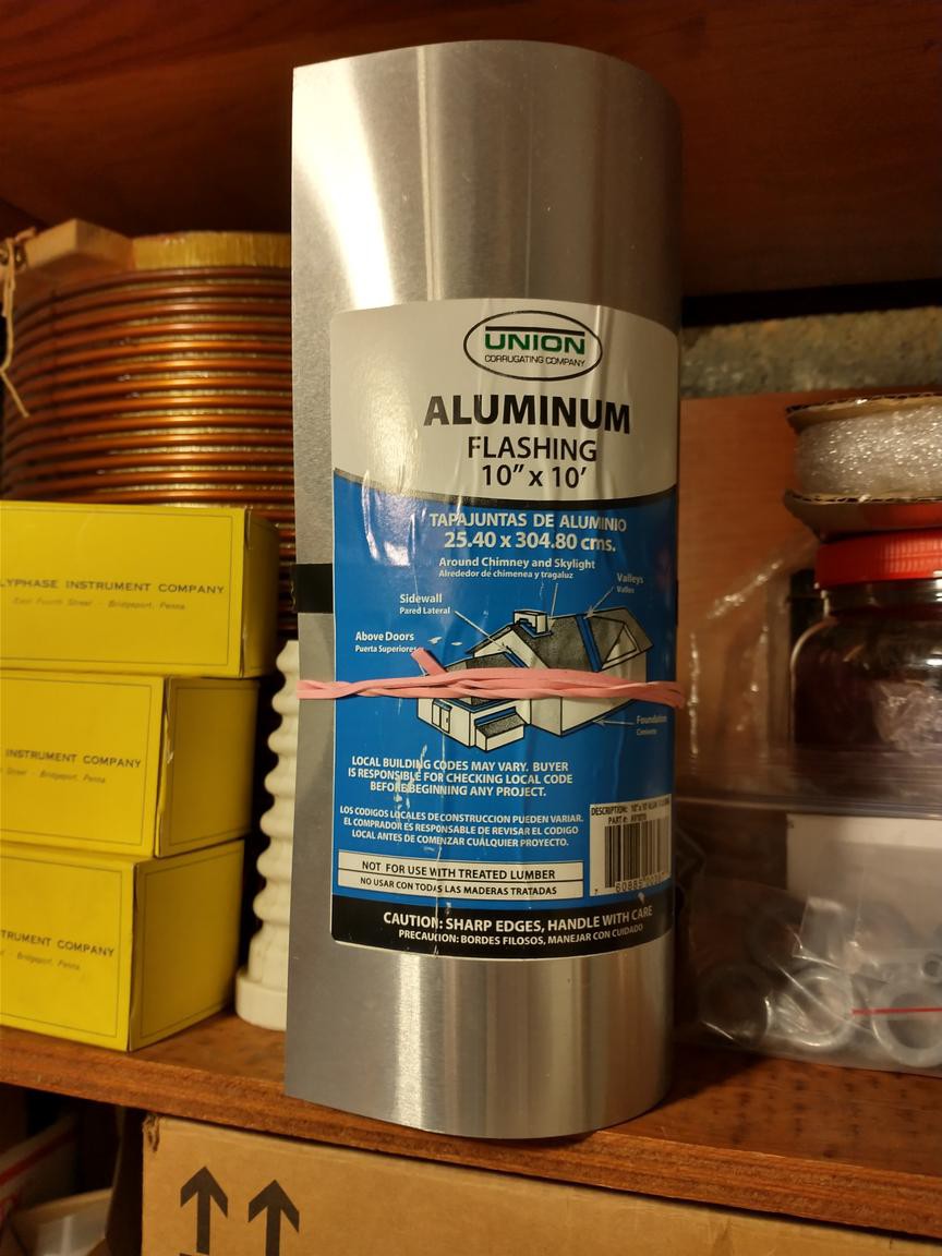
So I breadboarded the circuit and fired it up, feeding it a 5 V peak-to-peak, 4-bit, 1-kHz sine wave. It worked, but the transistors quickly became too hot to touch. I could try to source higher-beta TO-220s, but Halloween is near and there are children to terrify. Time for some quick Appalachian Engineering (as a former Knoxvillian I'm allowed to say that). Heatsink material:
Thermal-adhesive ingredients:
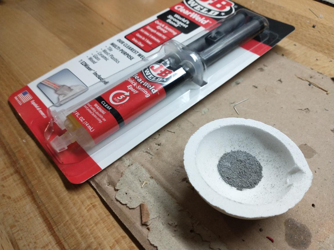
That's regular epoxy and aluminum filings.
15 mm x 15 mm aluminum-flashing square, with 2N2222 and 2N2907 (the complementary PNP) attached by 50-50 mixture of epoxy and aluminum filings:
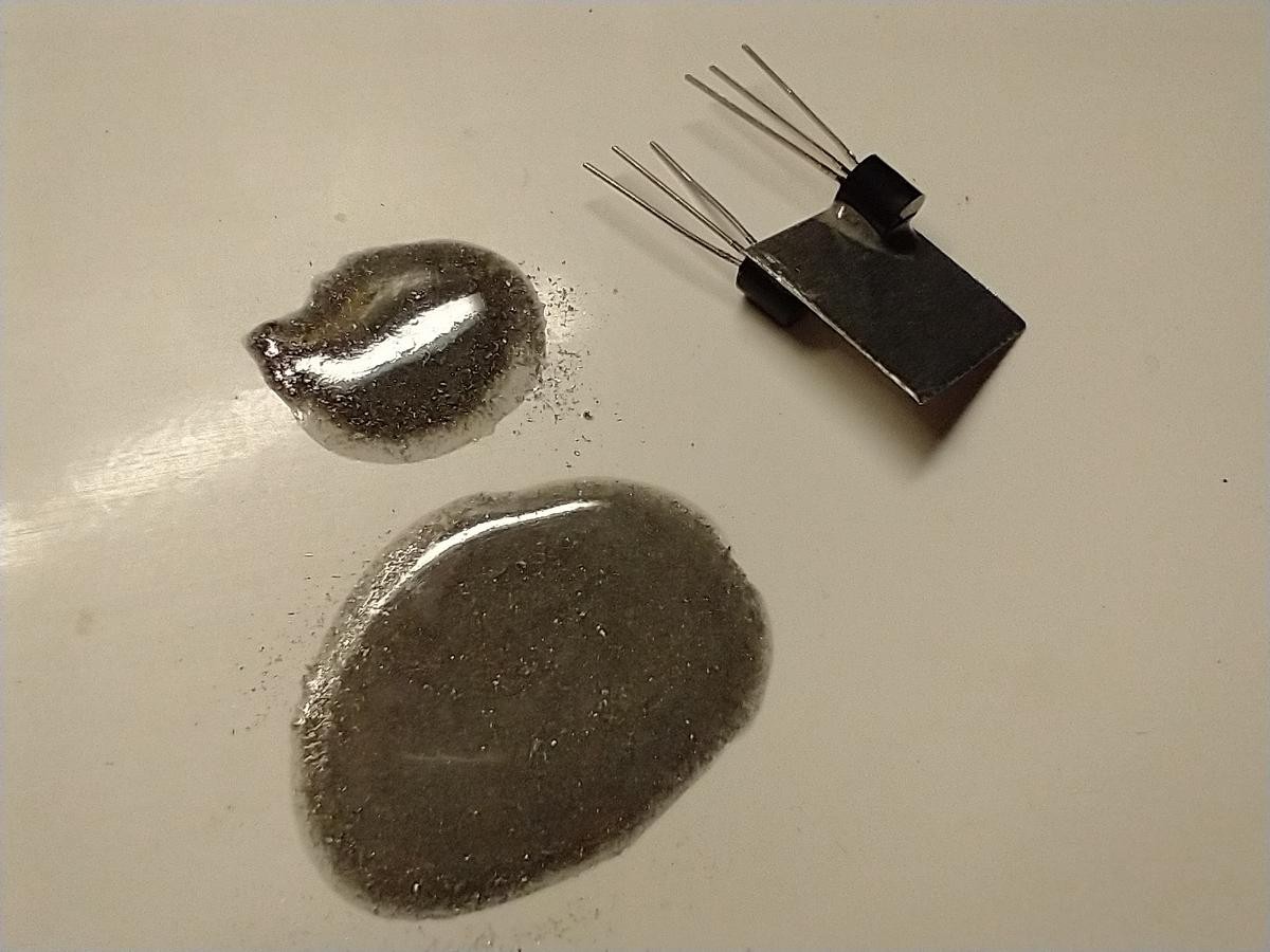
Do scratch the heatsink surface a bit for good adhesion.
A bespoke power-amp shield:
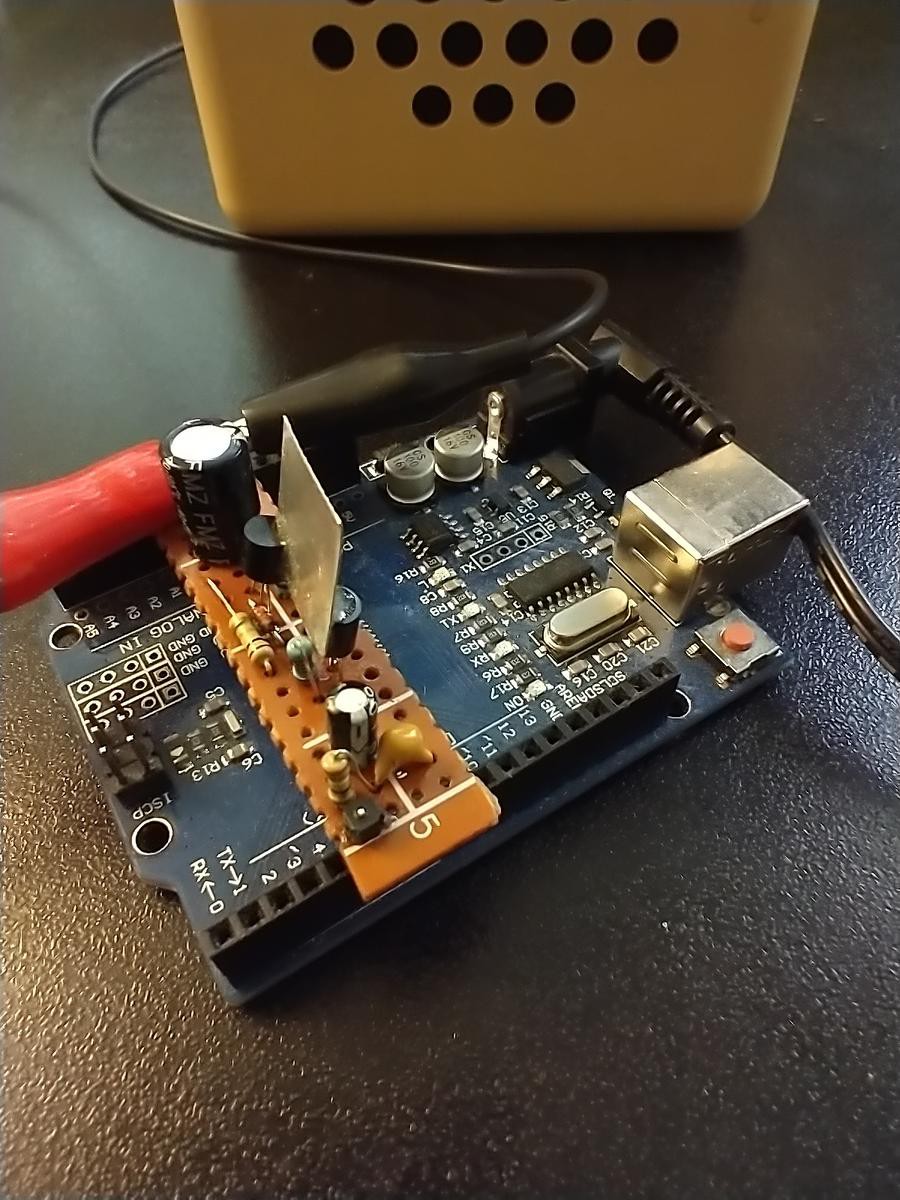
Close up with seductive lighting (the perfboard looks edible, I guess my phone decided it was food):
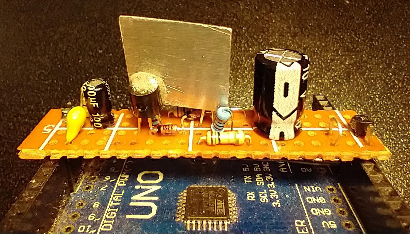
Left to right: the input signal to the power amp is PCM audio on digital pin 5 on this Uno clone. An RC low-pass filter to suppress the PCM carrier frequency, input coupling cap, Class AB amplifier stage, output coupling cap and connectors to alligator clip the speaker to.
The impromptu heatsink does work in some preliminary testing. Anecdotally it allows the power amp to operate at full blast for several minutes, keeping the transistors cool enough to touch. The original, breadboarded version (without heatsink) starts acting flaky after about a minute of operation and the transistors become too hot to touch well before then. The bias diodes do a good job of preventing crossover distortion. My scope tells me that the amp puts about 230 mW into the speaker, and the waveform looks pretty good, with less distortion than I expected. The output is surprisingly loud. Even after putting the loudspeaker face down to dampen the sound, I ended up wearing earmuffs for comfort during testing.
I hope to use this Mk2 power amp for a Halloween project (with only two weekends left to finish it up). Based on how it holds up I might revisit a couple of things, including testing alternative TO-92 heatsink configurations and looking for a TO-220 power transistor with higher beta than TIP29C.
Discussions
Become a Hackaday.io Member
Create an account to leave a comment. Already have an account? Log In.