 Fabian
You may have noticed that, in addition to the first version of the hub including pitch actuator, I have now also designed a second variant (with which I am much happier).
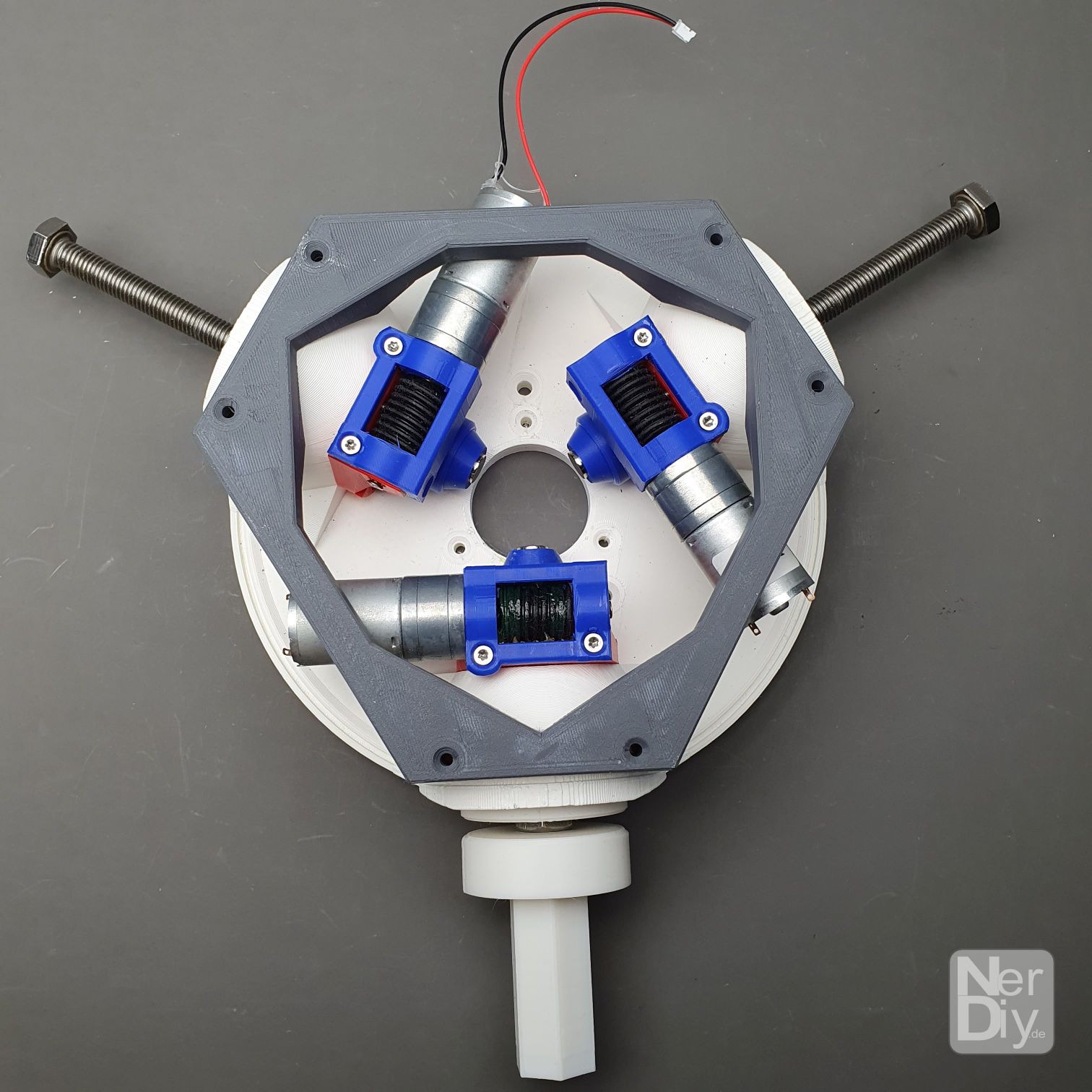
Even if the first version works, I noticed (at the latest) during assembly that the construction is a bit over-over-engineered. Yes, one could have guessed it beforehand, but in this case it was reality that bumped me over to conviction.
Because it was only during the (due to the many parts) quite complicated construction that I noticed that it is totally nonsensical to be able to adjust each wing independently of each other. Ultimately, the angle of attack is always adjusted for all wings at the same time. So why should you install three servomotors including sensor electronics if ultimately all wings should have the same angle of attack anyway?
Right. I didn't know why either. That's why I started with a complete redesign of the hub.
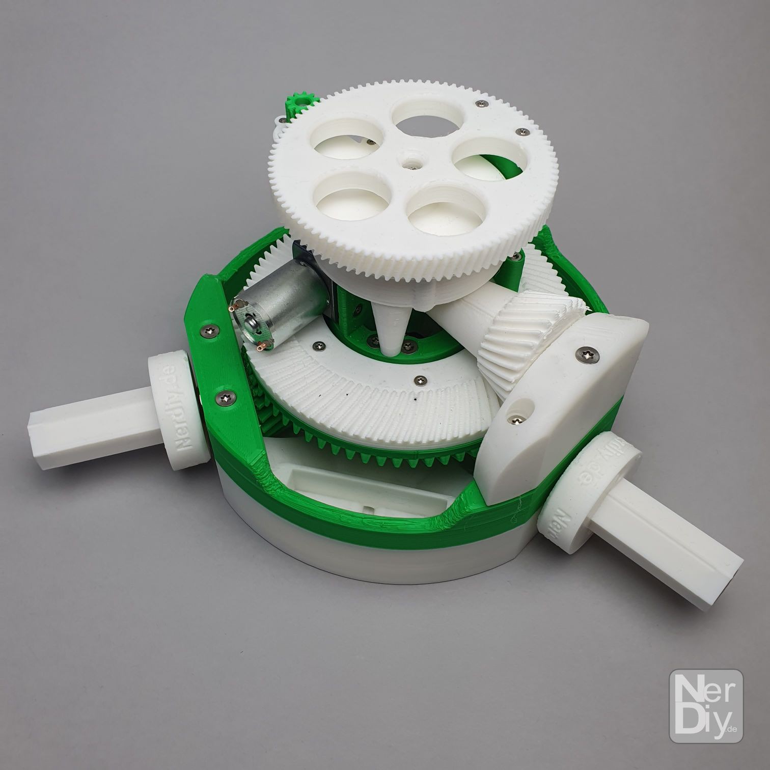
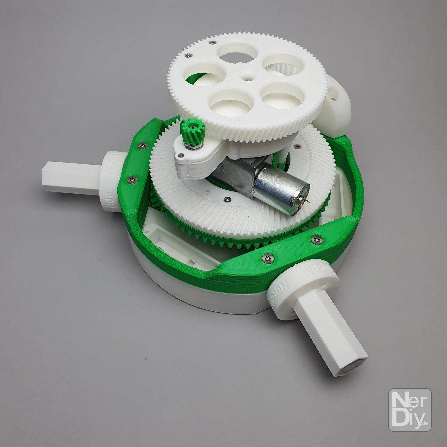
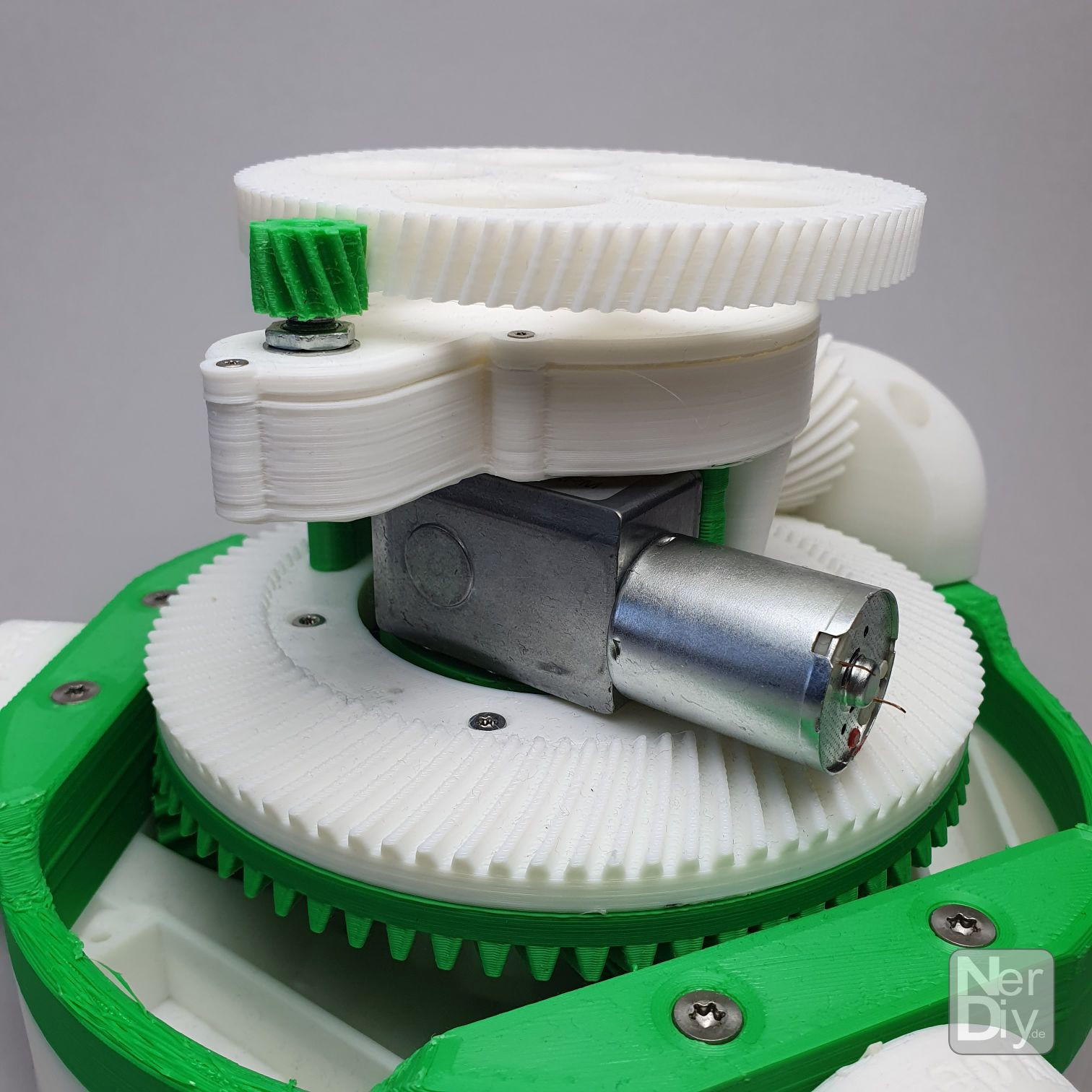
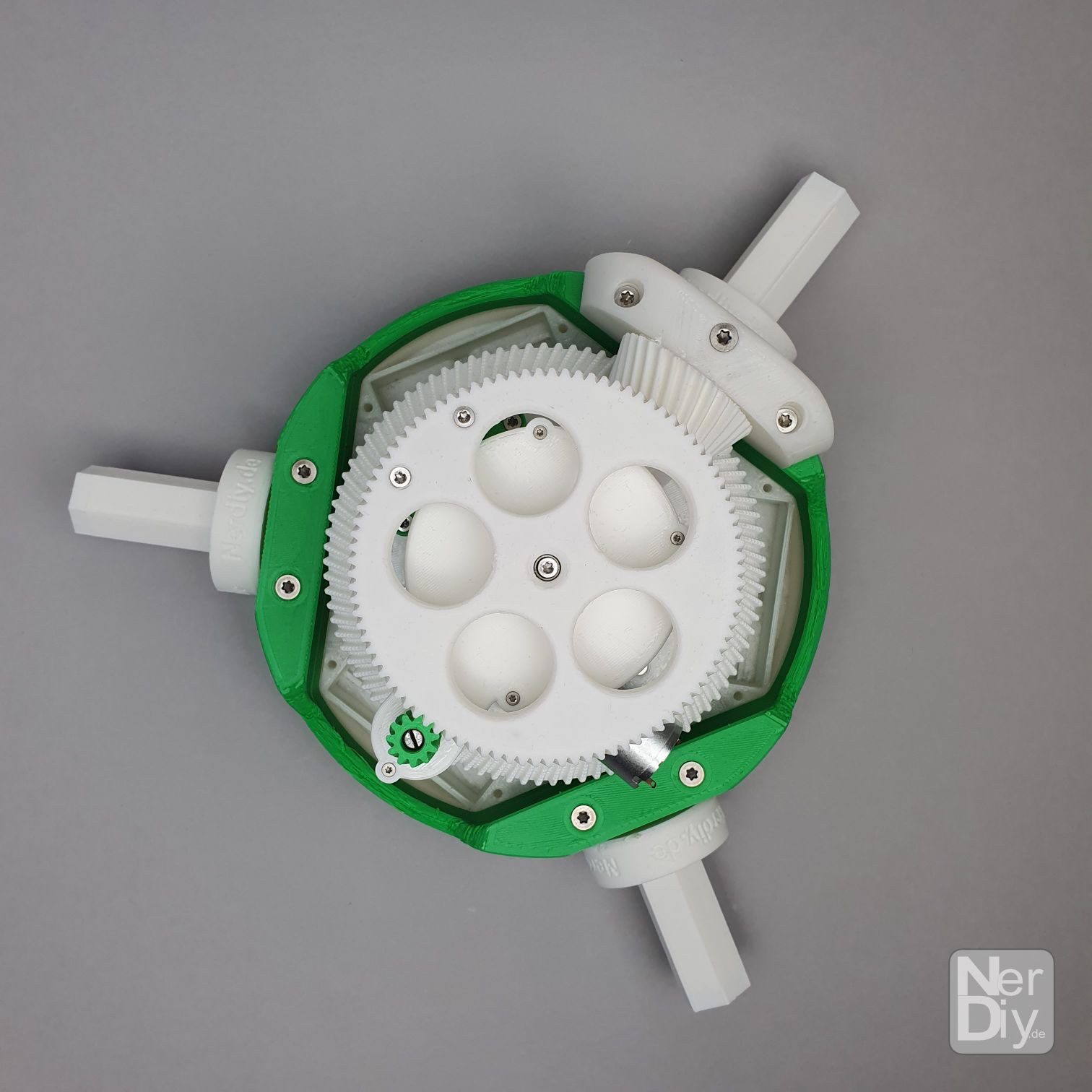
In this design I only use one actuator and one position sensor. The position sensor was (also due to the shortage of chips) exchanged with a simple 270° potentiometer. I have also integrated a small reduction gear for the position feedback so that the approx. 270° setting angle of the potentiometer can be used for the entire measuring range. In this way, the possible blade angle range is translated from approx. 60° to the 270° of the potentiometer. Ultimately, you can measure the set blade angle more precisely.Here are some videos and pictures that hopefully show how the new hub/pitch actuator shall work. In one of the videos you can also see the mechanism that will be used to mount the blades to the hub.
So, I'm always looking for feedback. If you have anything, let me know about it. :)
Discussions
Become a Hackaday.io Member
Create an account to leave a comment. Already have an account? Log In.