 kelvinA
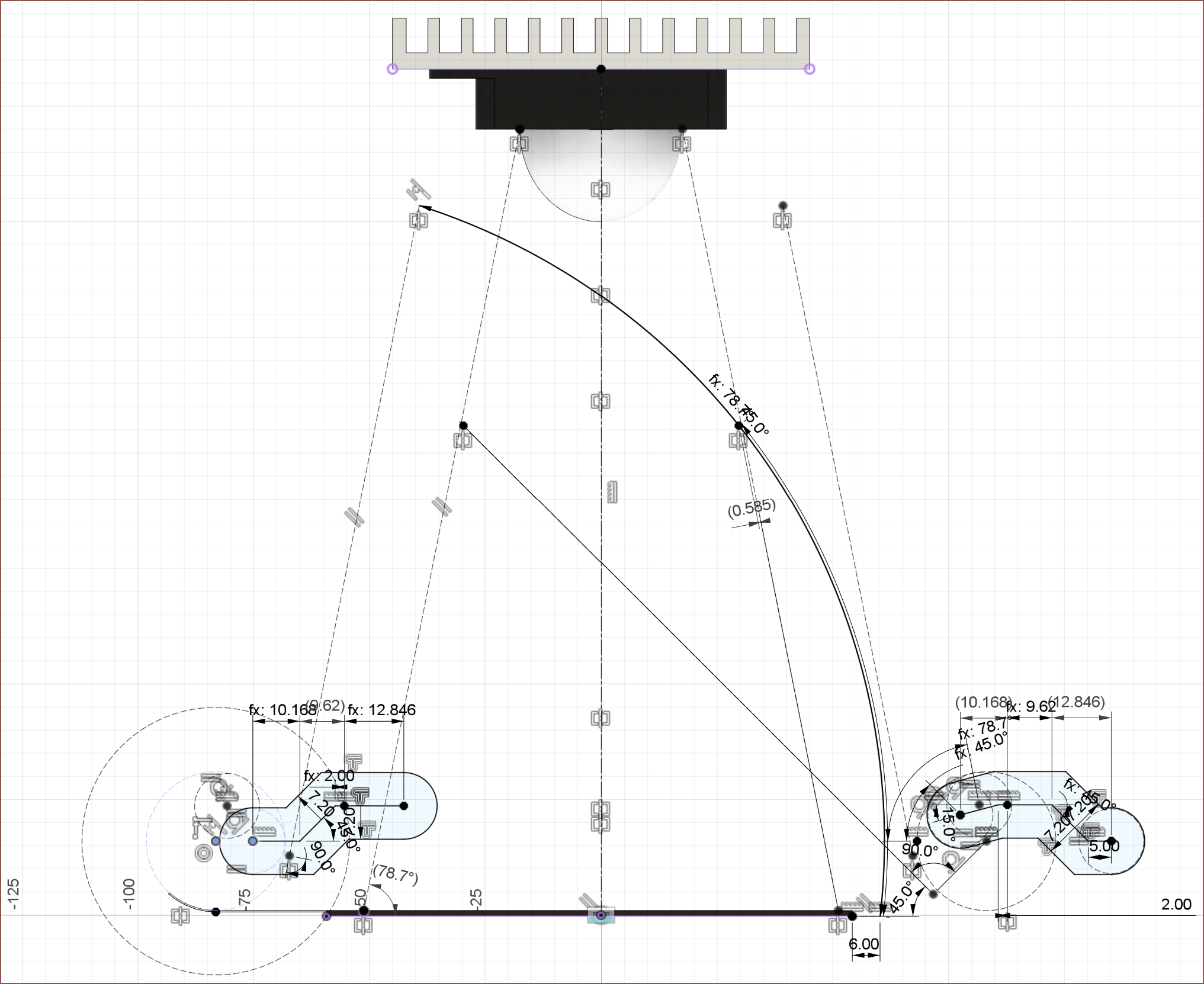 I'm going to refine this, but this is what I came up with.
 Originally, when I thought about using servos, I planned to use 2 -- one for each arm. However, once I got to thinking about the torque requirements for keeping the LCD down and problematic powered-from-off states the arms could be in, resulting in component damage, I wanted to revisit the idea of using 1 motor for both.
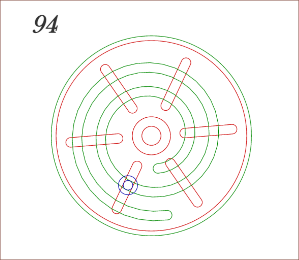
The idea I had going into it was some kind of incomplete gear solution.
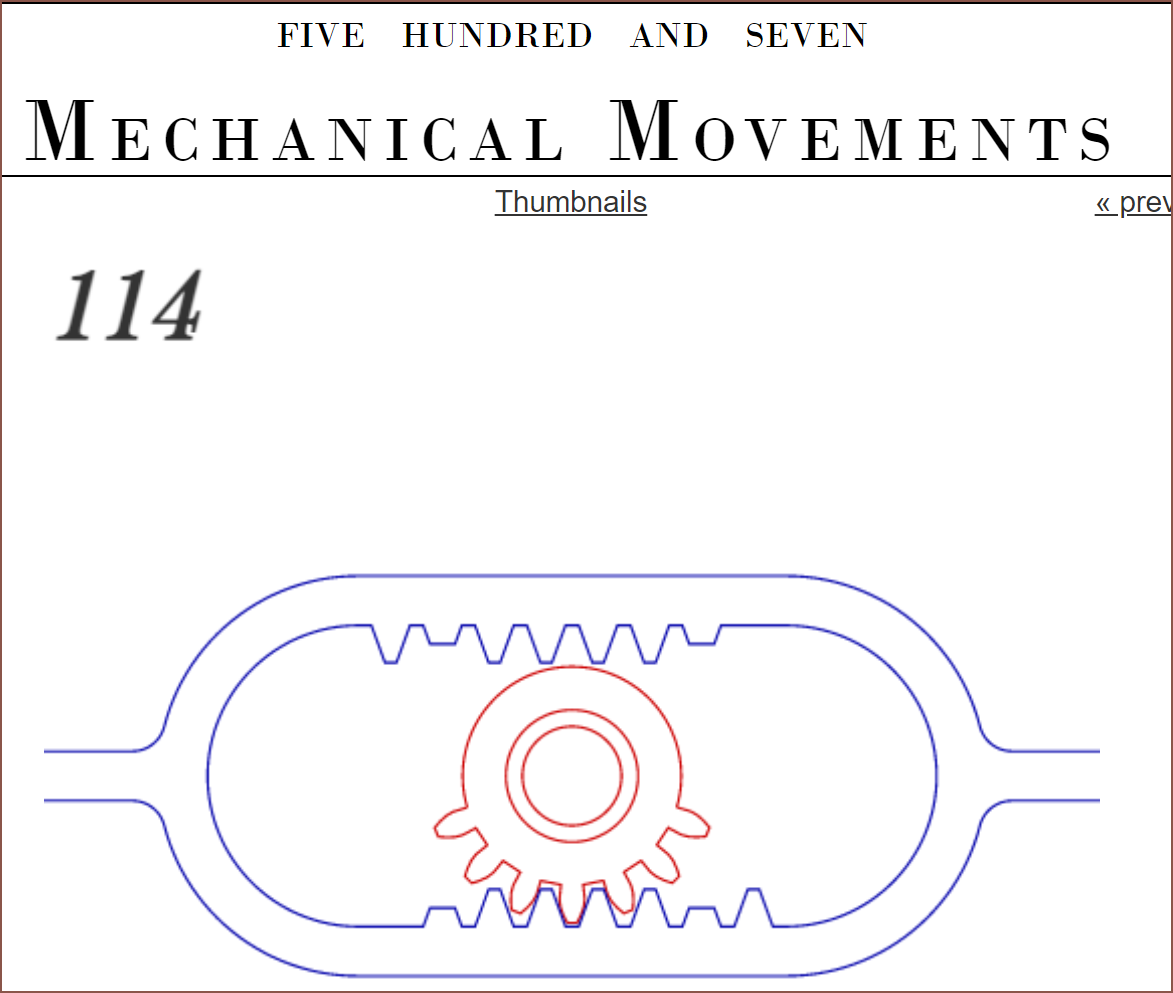 I was worried about the modelling complexity (and that's the reason why I had the servo idea instead of using a stepper), and I didn't like the idea of relying on magnets to keep the panels up when the drive gear wasn't in contact with the driven gear of said panel. Additionally, I may need a high torque motor to prevent the LCD panel being pushed back up.
 I'm not sure how much friction these kinds of things have, so I've just used a 5x14x5 bearing in the design for now. It is very most likely going to be replaced by an 8mm smooth rod/steel dowel.
Movement explained
The track has 2mm long horizontal sections after a movement for lower tolerance requirements of the servo. Additonally, I'm thinking of moving the servo somewhat slowly (180 degrees per second) to cut on noise.
- This configuration starts with the LCD panel all the way down on the surface of the film and the Charge panel at 45 degrees. As you can see from the Charge panel will almost completely cover the expected light path of the UV lamp.
- Leftwards movement of the groove track from 0 - 10.18mm will slowly move the Charge panel until it is parallel with the expected light path and thus completely out of the way. The LCD panel hasn't moved. This is to control how much of the screen is exposed to UV light in an effort to increase longevity when only part of the screen is needed to expose a part of the layer.
- The next 9.62mm of movement will (relatively quickly) move the LCD panel so that it is also parallel to the expected light path on the other side. Now the configuration is in a position to cure the layer.
- Moving the track another 12.8mm will move the Charge panel down against the film. As you can see by the horizontal move in this part of the track, any force that attempts to push the panel up will be counteracted by the force exerted on the bearing pushing on the side of the track. This is the same for the LCD panel, thus the holding force of the panels are not dependent on the torque of the motor.
Discussions
Become a Hackaday.io Member
Create an account to leave a comment. Already have an account? Log In.