 Mrinnovative
PCB-to-control-Stepper-motor-without-arduino
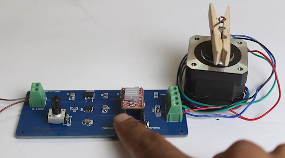
Hello friends this time I have developed a IC 555 based controller to control stepper motor This controller can control speed as well as direction of stepper motor.
This small PCB based controller is very handy to test A4988 stepper driver IC and Stepper motors. The main plus point of this controller is it does not required any coding. Those of you have worked with stepper motor at any point of time
they must know it is too much pain to run a stepper motor Traditionally we need a microcontroller then we need a stepper driver IC then we need to write code to run stepper motor then we need to upload that code to our microcontroller. All after this, we are able to run or stepper motor.
Suppose you just need to check your stepper motor or A4988 stepper driver or you need to run stepper motor for any simple application you have to go through traditional way
However, by using this controller simple just connect stepper motor wires and connect power supply to PCB that is it you are ready to go.
The PCB controller which I have used in this project is ordered from JLCPCB.com Further in this post we will learn in depth about how this controller work
VIDEO
I also have a full video on this project on my youtube channel youu can watch the full video you will get most of the idea by watching this video to watch video juct click on above image
HOW STEPPER MOTOR WORKS
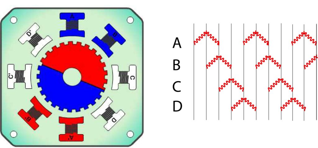
Before going further first we need to know how actually stepper motor works. stepper motors are very much different and complex from traditional DC motors Stepper motor runs in steps as name suggest. Basically stepper motors are brushless DC motors, normally a permanent magnet rotor placed in between of stator winding.
Stator winding then energize step by step in a sequential way so it get magnetize and force rotor to align with the magnetic field of stator coil.
in this way rotor begin rotate in small steps, due to this behavior the motor gets its name “stepper motor”
As we can see now by controlling the stator winding generations sequence we can precisely control the position of rotor without any position feedback system.
this quality of stepper motor makes is best suitable to be used were high precision motion is required like CNC machines.

Also here we have to note another best quality of stepper motor is High torque at low RPM & Holding torque.
We know that rotor of stepper motor rotates by sequentially energising stator coils.
if we energize a single set of coil with time delay respectively we get slower RPM of stepper motor.
hence we also get high torque because rotor is always in hold within the magnetic field of energized stator coils.
If we keep energize a single set of stator coil the rotor will be stay on its place with maximum torque.
Driving methods
Single coil excitation mode There are many methods to drive stepper motor. how stepper motor works with single coil excitation is basic method to drive stepper motor. 
Full step Mode In full step drive mode 2 coils are excited at same time because of this it provide higher torque to the motor. 
Micro-stepping mode Micro stepping mode is the now most famous way to control stepper motor, high precision can achieve by this drive mode. Micro stepping mode give smooth and silent motion to stepper motor by providing variable controlled current to the coil in form of sine wave.
STEPPER DRIVER IC
Till now we learn how stepper motor works, now we will see what we need to run stepper motor So we have a stepper driver IC which we known as A4988 there are many other stepper driver IC more or less all are work on same principle.
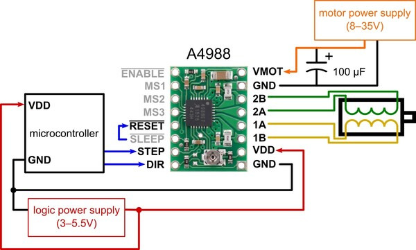
The A4988 is a microstepping driver for controlling bipolar stepper motors which has built-in translator for easy operation. This means that we can control the stepper motor with just 2 pins from our controller, or one for controlling the rotation direction and the other for controlling the steps.
In this way we now understand we need two types of signal to run stepper motor through A4988 stepper driver IC one is STEP singla which is in square wave in nature and one is DIRECTIONAL signal which is normal digital signal in nature.
In this way we can conclude that we can use IC 555 because we can generate adustabel square wave using IC 555 by using POT with IC 555 we can also control the speed of stepper motor
Now we are clear with the theory now we can move towards our controller
IC555 BASED STEPPER MOTOR CONTROLLER


COMPONENT USED

A simple 555 Timer Stepper Motor Controller Circuit is designed with few easily available components. This circuit makes stepper motor to drive continuously without any interruption or step stop. By using this circuit we can drive unipolar stepper motors with different voltage ratings. Keep in mind that this circuit uses only 9V power supply and capable of drive stepper motors under 12V. If you want to drive higher than 12V stepper motors then add external power source to stepper motor and power switching transistors.
CIRCUIT DIAGRAM

This is the circuit diagram of the controller
First of we TB (terminal block) here we will connect power supply
then the applied voltage passed through polarity protection diode D1 This Diode D1 save our circuit from cross polarity
then the supplied voltage given to the IN pin of 7805 and GND is connected to the GND pin of 7805
7805 Is a voltage regulator IC it convert input voltage to 5V output voltage we need 5V in A4988 IC so we added this LM 7805 voltage regulator IC in our circuit.
Further, we have on Green LED this will indicate that PCB is powered ON Further, we connected the 50K ohm potentiometer to the DIS pin of IC 555
This will control the charging and discharging time of capacitor C3 & C4 In result we will get adjustable Square wave at OUT pin of IC 555.
By rotating POT we will change the speed of stepper motor and by pressing the push butting we can change the direction of stepper motor
PCB DEVELOPMENT


I have design this PCB in easyEDA software this PCB have mostly surface mounted components. it is a 2 layer PCB .
I always prefer JLCPCB.com for my PCB needs, JLCPCB.com have best deals for their customers $2 for 1-4 Layer PCBs, free SMT assembly monthly.
If you seriously need quality PCB quickly in your hand then you must have to try JLCPCB PCB manufacturing service. They have Special offer of $2 for 1-4 Layer PCBs, free SMT assembly monthly. If new user signup today from this link JLCPCB.com you will get welcome coupons from JLCPCB.
SMT Assembly service of JLCPCB.com is cherry on top now get your PCB fully assembled and save your time and money Select components for your PCB from there Parts Library of 200k+ in-stock components they are offering $30 valued New User coupons & $24 SMT coupons every month $8.00 setup fee, and $0.0017 per joint
Now no need to order components separately for you PCB and get free from stress of soldering them on PCB just try PCB SMT assembly service and get you PCB with components pre assembled and ready for the project
👉 Try PCBA service of JLCPCB.com and save your time and money, get PCB ready for project, 200K+ components in library of JLCPCB.com as well as 3rd party parts to choose from. Assembly will support 10M+ parts from Digikey, mouser
👉 $30 valued New User coupons
👉 $24 SMT coupons every month
For more detials & offers please visit JLCPCB.com
