 Toon Van Eyck
I always knew I would dread creating the design files for all 48 flaps of the display. So I didn't!
Why do something in an afternoon when you can spend 3 days coding a program to do the task!
This is the solution I came up with:
SVG's:
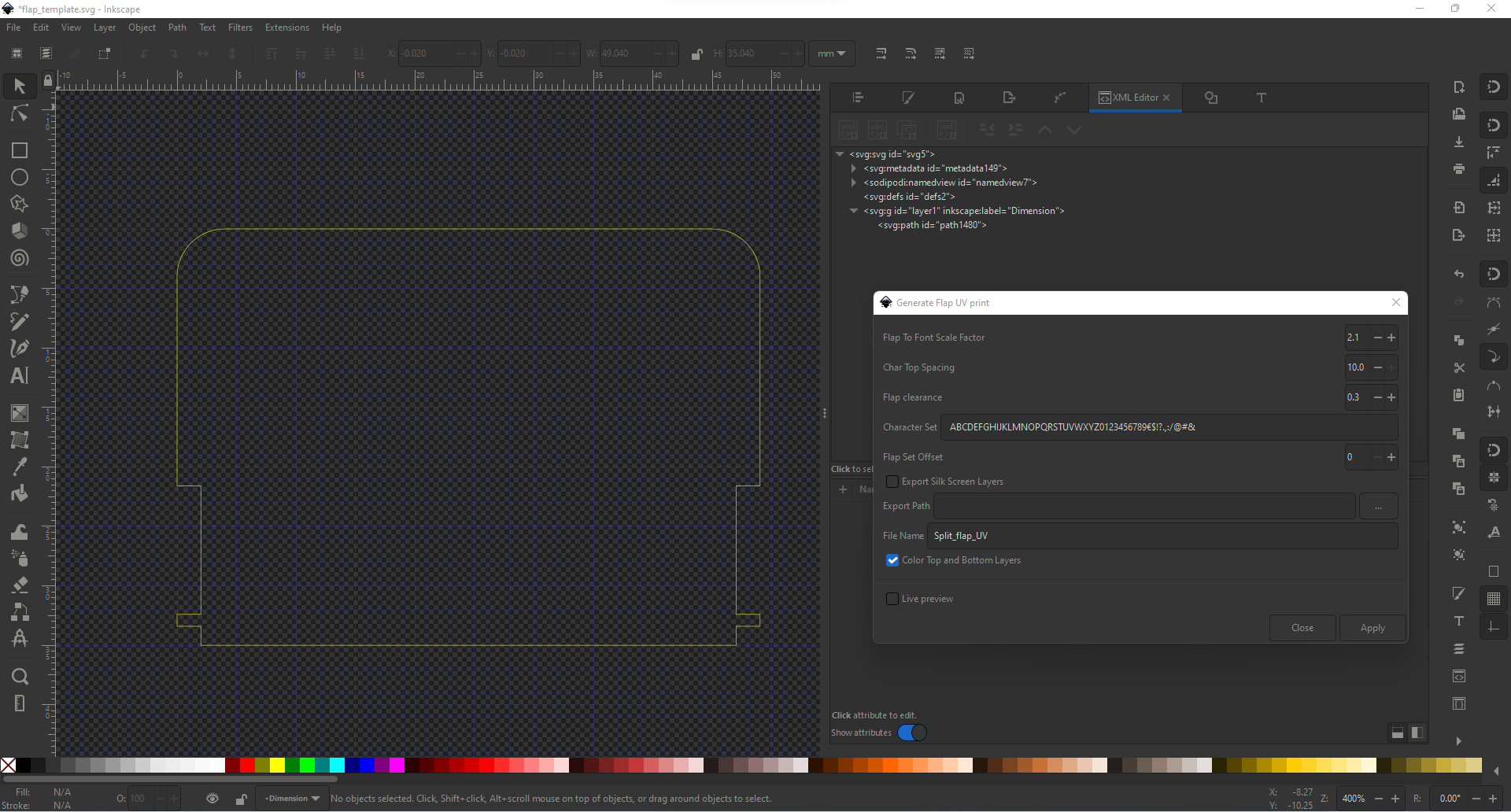
First I created a template file with the flap board-outline on a layer called "Dimension".
I wrote an extension that loops through a list of characters, places them in the svg file, cuts them in half and positions them. Two (half) characters are placed per iteration, each on a separate layer, called tPlace and bPlace. Each flap is separately exported as svg file.
Eagle .scr:
Now that we have a list of svg files, we need to find a way to import those files into eagle board designs. There is a great tool by Gordon Williams for converting an svg into an eagle scr files. I forked his project to allow me to upload and convert multiple files at once. I also changed his script so the layer used by the eagle script is the same as the label of the Inkscape layer. These changes greatly improved my workflow, though the UI had to suffer...
gerber zip's:
Next I created a batch script that utilises the eagle command line interface to run the eagle scr script and export all the different gerber layers. These gerber files where the combined in a zip file, which can be uploaded to your preferred PCB manufaturer.
The bad news:
The Inkscape extension is not flawless some characters that are not "full height", like: "." and ",", don't play nice with the script and end up in the wrong place. Also depending on the font, some characters have a different weight and look out of place. Those characters must be manually modified.
Discussions
Become a Hackaday.io Member
Create an account to leave a comment. Already have an account? Log In.