 Caleb W.
After waiting ~2weeks, I have my parts from DigiKey and 3 prototype boards from OSHPark. I'm a huge fan of their 'after dark' option, especially since it's the same price as the regular puple soldermask. The traces have really great contrast against the black substrate that give it a sophisticated-but-older look. Strangely, none of the silkscreen was printed on either side of the board, which I'm pretty sure is an error on OSHPark's part, but honestly it isn't that critical since most of the lettering was done on the copper layers.
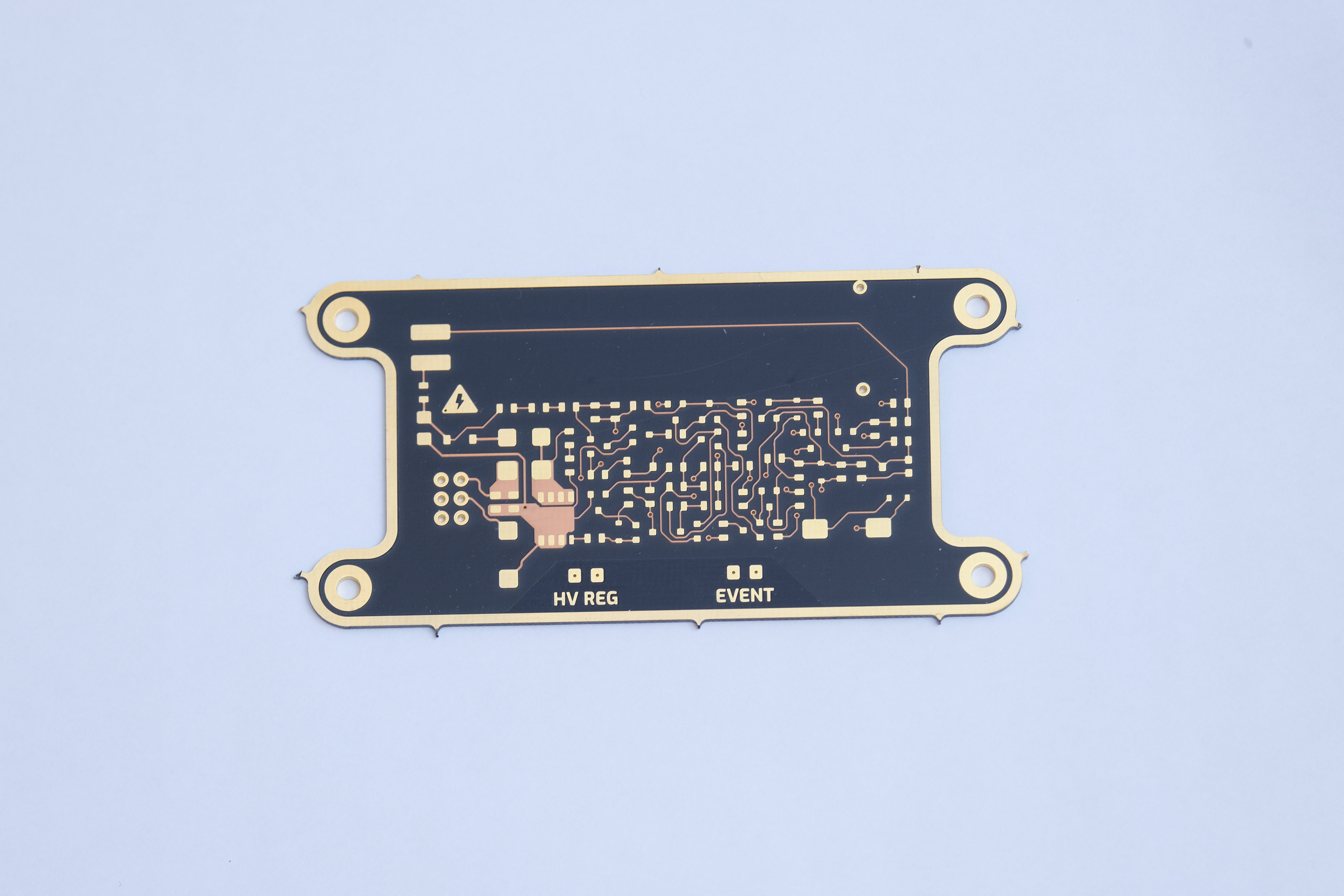
Assembly was pretty straightforward with 0805 size components. And it passes the magic smoke test on first power up! It's always a relief when theory actually matches real life for once :) Of course, there were a few passives that needed tweaking. Nothing too major - mostly the components involving the detection side. C13 I decided to change to 10nF for better immunity to voltage drifts on the high voltage, although this shouldn't really make a difference. R24 and R27 I adjusted to give a better usable sensitivity range via VR2. With the original schematic, geiger pulses were *barely* audible through the speaker, so I reduced R23 to 4.7k and replaced the flyback diode with a 10nF cap. It's still pretty quiet, so for future versions I may experiment with lower impedance speakers or switch to a piezoelectric one. The pulse stretcher circuit for the LED was way too short initially, and I eventually figured out that the C11 wasn't able to discharge completely during pulses. Since there wasn't an easy way to increase the discharge current dramatically, I opted for a 10nF cap and 100Meg charge resistor. This gives flashes that are ~300mS long for decent visibility. Also, for reason the snubber circuit across the main FET wasn't tuned right, so I reduced R5 to 100ohm. It isn't perfect, but it's good enough that I'm not going to bother fiddling any more.
Setting the output voltage is tricky because of the very high output impedance. Even a 10Meg multimeter input impedance will drag the voltage down out of regulation. After experimenting with different setpoints, I set VR1 to ~30% of the max output voltage. I'm guessing the output voltage is 360 volts or so, but I can't say for sure until I buy or make a high impedance probe.
At 6V, the entire circuit draws about 5mA, although the majority of that current is flowing through the indicator LEDs. With a setpoint of 360-ish volts, it stays in regulation down to a battery voltage of 3.75V. After dropping below this point, the step up converter is on constantly and the input current rises exponentially to a max of 100mA. Of course, the CR2032 cells wouldn't be able to support this much current, especially when discharged to 1.9V/cell. It's difficult to find data on CR2032 capacity vs discharge rate, so I'm going to have to determine that experimentally. I estimate ~20hrs of continuous operation until the output falls out of regulation.
Background CPM is 15-17 in Oregon where I live, which seems to be typical for the SI-29BG tube. Bringing a few Uranium UV fluorescent beads close to the tube results in readings in the range of 50-70 CPM. I don't have any other check sources at the moment, but soon I will be exploring some abandoned Uranium mines where I will be able to do further testing.
Discussions
Become a Hackaday.io Member
Create an account to leave a comment. Already have an account? Log In.