 John
JohnSo, I decided to design a PCB for my project. This PCB hosts the "Dummy Terminal" circuits and is referred as "Computer Terminal Board" on the PCB. I used Grant Searle's schematic of the "Video & Serial/Keyboard Interface" (named "Video&Keyboard,SerialBoard" in the project Details section), with just minor modifications: 1. I added two ICSP ports for programming the microcontrollers without physically removing them from the circuit. 2. Decoupling capacitors were added to all 3 ICs.
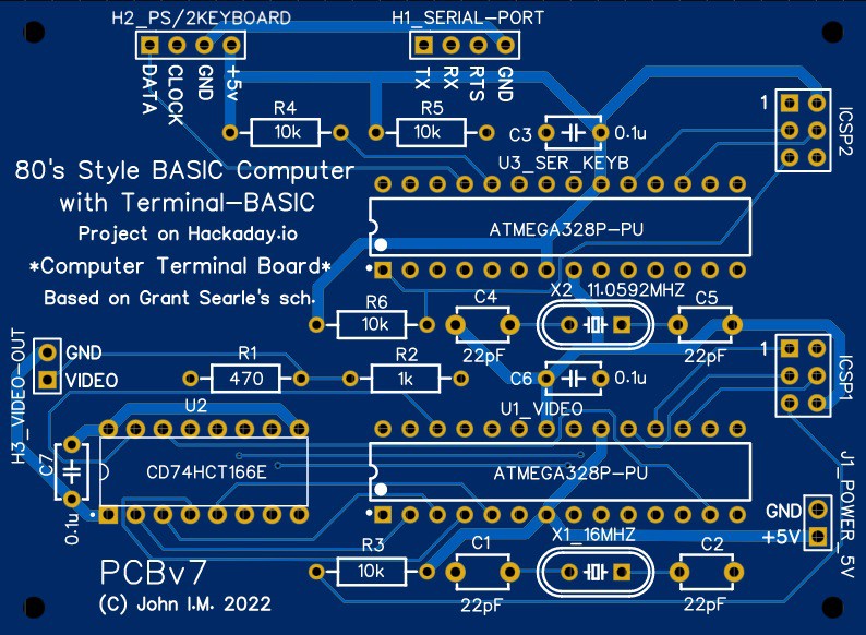
This particular design of the PCB is double-sided with vias.

As soon as I receive the actual boards I'll post some update. Hopefully, this PCB will give the "80's Style BASIC Computer with Terminal-BASIC" a more robust "body" after the successful testing of the project on breadboard.
P.S. About the ICSP headers: The need to add ICSP (InCircuitSerialProgramming) headers on this board was realized when I tried to modify the software in the ATmega328P's (specifically, the "Video" ATmega328P) in the breadboard prototype. Each and every time, I had to remove the chip from the breadboard and insert it into a separate programmer (STK500); this proved to be cumbersome. The other alternative is to leave the chip on the PCB and use ICSP programming; for that, you use only 6 pins of the IC, which are broken out to the ICSP header. Just connect a serial programmer to the ICSP header (I used the STK500) and program the chip in place.
Discussions
Become a Hackaday.io Member
Create an account to leave a comment. Already have an account? Log In.
Thanks for the comment. What I did was take a paper print of the Searle design and draw a schematic in a pcb cad software; then I cross-checked (x3) the paper print against the cad schematic and the pcb connections against the paper print again. So, fingers crossed, I hope it will work without problems; in any case, I'm always eager to troubleshoot if need be. Although the presented design is version 7, I have already developed the board to version 10, with minor improvements. No connection modifications, of course, just some slight changes to components positioning.
The "Power zones" you mention would be some kind of GND plane on one side and VCC plane on the other side, so to say?
Contouring the corners were never an issue, regarding me, since I have an inherent sympathy for square boards. :-) Also, I expect the board to be housed in some box and all connections broken out to panel-type connectors on the back of the box (keyboard, video out, power). If the board is to be left lying around bare, though, you have a point! So thanks for mentioning; I have to consider that part.
Are you sure? yes | no
Nice design. Hope it will work as expected, once produced!
Don't you think about making spare area of the board to be power zones (i.e. Front - +5V, back - GND) and making the board corners less sharp?
Are you sure? yes | no