 Eric Hertz
This is my own invention... Maybe someone else has done it, maybe it has someone's name attached to it. I dunno. (Maybe not, and I'll finally hear from someone who can get me a patent?)
The idea is simple enough... I'll go into detail after the first image loads:
A typical method for decoding a digital quadrature rotary encoder involves looking at each edge of each of the two signals. If One signal "leads" the other, then the shaft is spinning in one direction. If that same signal "lags" the other, then the shaft is spinning in the other direction.
This is very well-established, and really *should* be the way one decodes these signals (looking for, then processing, all the transitions).
This is important because of many factors which we'll see if I have the energy to go into.
...
An UNFORTUNATE "hack" that has entered the mainstream does it differently. It's much easier (but, not really).
The idea, there, is to look for the edge(s) of one of the signals, then when it arrives, look at the *value* of the other signal.
This is kinda like treating one signal as a "step" output, and the other as a "Direction" output. But That Is Not What Quadrature Is.
If the signal was *perfect*, this would work great.
But the real world is not perfect. Switch-Contacts bounce. Optical encoder discs may stop rotating right at the edge of a "slot", a tiny bit of mechanical vibration or a tiny bit of 120Hz fluorescent lighting may leak into the sensor. And obviously electrically-noisy motors can induce spikes in decoding circuits as well as the encoders'.
That "Step" pulse may oscillate quite a bit, despite no change in the "direction".
...
My friggin' car's stereo has this glitch. And now that the detents are a little worn, it's very easy to accidentally leave the volume knob atop a detent, where suddenly and without warning a bump in the road causes the volume to jump up, sometimes an alarming amount, even though [actually /because/] the knob itself still sits atop that detent.
This Would Not Happen if they decoded the quadrature knob correctly. That was the whole point of the design behind quadrature encoders, as far as I'm aware.
But then somehow it became commonplace to decode them *wrong*, and I'm willing to bet it's in so many different devices these days that at least a few folk have died as a result. (It's sure given me a few scares at 70MPH!)
"Hah! That's a one in a million chance!" Yeah? But if you plan to sell 10 million... Sounds like ten counts of first-degree manslaughter to me. What's that... Ten 20 year prison sentences? But, yahknow, since "Corporations are people" it means the end of said corporation, and prison sentences, not slaps on wrists, for those who knowingly aided and abetted.
.
.
.
So, let's get this straight:
Quadrature can be decoded correctly.
The "step/direction" method is NOT correct.
.
.
.
If the elite engineers who hold onto trade secrets like this technique are unwilling (or just too tired) to teach you, and there's even the tiniest chance a glitch could hurt someone, then please remember that the internet is full of seeming-authoritative information from folk who really have no clue what they're talking about, and then look into products designed for the task, like HP/Agilent's HCTL-2000, or similar from U.S. Digital.
.
.
.
Now, As A /hacker/ or /maker/ or DIY sort of person, I often try to solve puzzles like the one I faced tonight: How do I decode my two quadrature signals with only one Interrupt pin and one GPIO pin and no additional circuitry?
So, ONLY BECAUSE it doesn't really matter in this project, I considered the "Step/Direction" decoding approach, which I'd dismissed so long ago that I'd forgotten exactly /why/. And I had to derive, again, the *why*, which I described earlier ("Noise" on "Step" would cause the counter to run away).
.
I spent a few hours trying to think of ways to resolve that, and ultimately went back to my original technique, just using two GPIOs, polling, and history to monitor both edges for the expected changes.
The problem is, it's a bit overboard:
This encoder outputs something like 8000 ticks per revolution(!?) and 100 would be plenty for my needs.
And, it really doesn't even matter if it misses some steps.
So, I can afford to sacrifice a whole slew of "ticks", and (need to) save a bunch of CPU power, too.
...
I put on my thinking-cap and realized I could reduce the quadrature-decoding processing time (and resolution) by 3/4ths!
*And* do-so by modifying the "Step/Direction" technique.
And do-so without introducing the step-runaway problem.
And do-so without introducing, I think, any additional chance for "missed steps" (except, of course, the 3 of 4 I'm intentionally skipping).
...

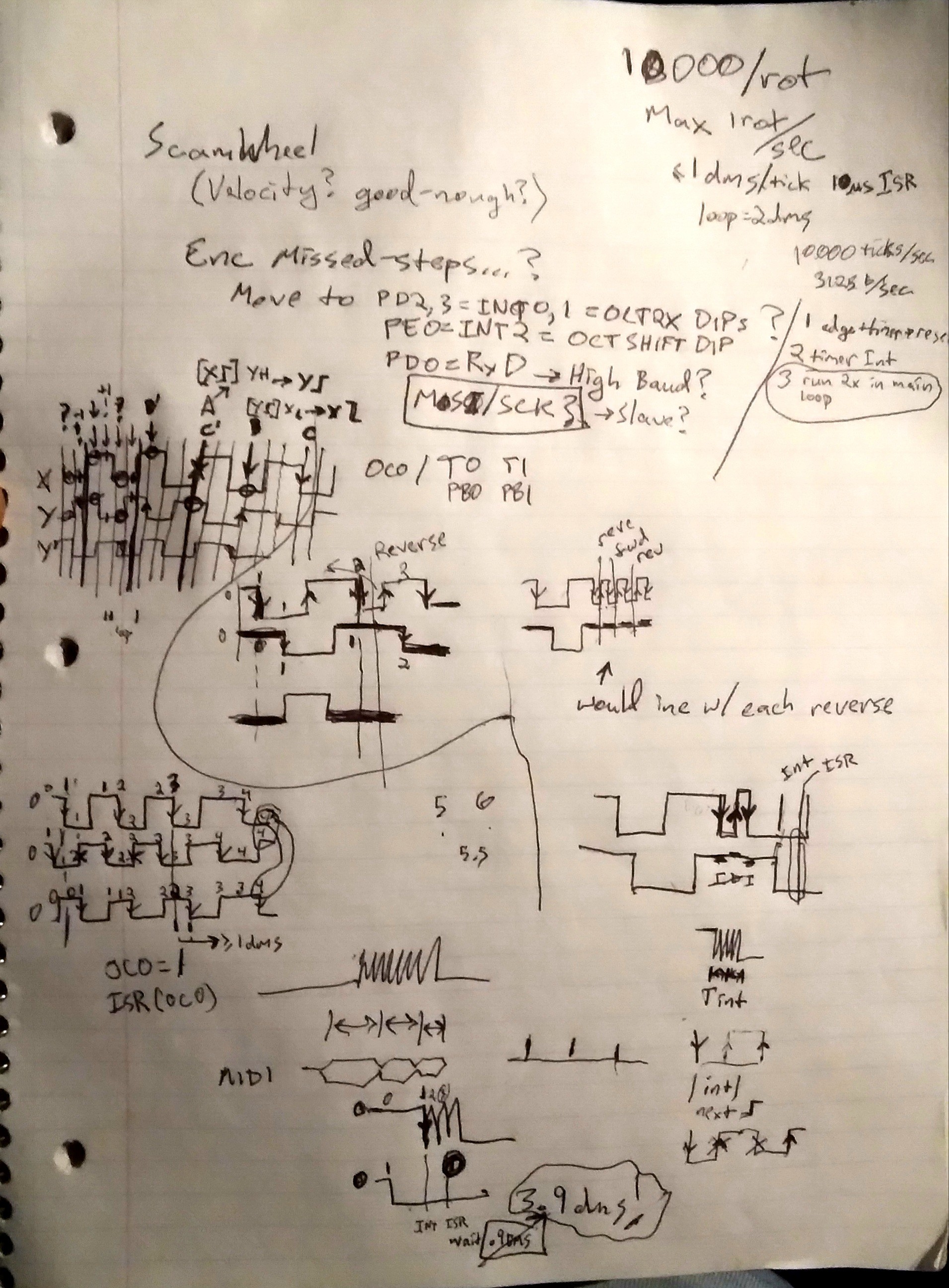
Here we have two quadrature signals, 90deg out of phase, on X and Y. Y' is when it spins in reverse.
On the left, with all the tightly-spaced arrows, we have the typical decoding-scheme. Wherein, it's important to register every state/transition (I call these 'ticks'). Thus, if this were 10000 ticks/revolution and I spin it at most 1 rev/second, we need to sample those GPIOs at least 10,000 times/sec.
(Note that since every state must be traversed, in order, a noisy/edge-case input (as described earlier for "Step") results in a value that may oscillate, but will not, can not, increase repeatedly.)
.
On the right is where it gets interesting.

Say we power-up the device just left of the position marked A, where both X and Y are low. We configure the decoder to look for a rising-edge transition (e.g. interrupt) on X. Turn the encoder to the right, detect the rising-X ("[X] Step"), measure Y=H ("Right"), position=1.
Now reconfigure to look for rising-Y. Why?
If we'd've chosen Falling-X, we might get triggers due to the runaway-stepping problem, if it stopped near A, or if electrical noise was high, or if the output bounces.
If we'd've chosen falling-Y, it would be the same as the typical decoder scheme; too high of resolution for my needs, too much processing time... Reducing the processing time this much, I can get away with much-faster (3x!) knob-turning, without missed-steps or actually using any interrupts. GPIO-polling should do fine.
So, if it went right, to B, X will be low, position++. Left, at B', X=H, position--.
Now, at B, we look for X-Falling, three steps away in either direction. Or, from B' we look for X-Rising.
And So On.
...
The key-factor involves looking for an edge on one input, then immediately after receiving it, switch to looking for a different edge on the other input. Why? Well, think of it like the ol' pushbutton-debouncing technique of using an SPDT button and a set-reset latch. When the first edge comes through, it flat-out stops paying attention to that signal (set is set already. Any number of bounces on the set input won't change that). That signal is now debounced. So, now wait for the "pushbutton's" "release" to reset the flip-flop. Again, if it bounces it doesn't change anything.
This is especially relevant in quadrature because when there's one edge, the other input should be steady (high or low) by design. So...
BWAHAHAHA!!!! NOPE!!!!
A couple days later I see the problem.
NOPE!
Because bounce on the next falling edge would mean a rising-edge we're looking for. Two ticks too early. Where the "direction" signal is inverted.
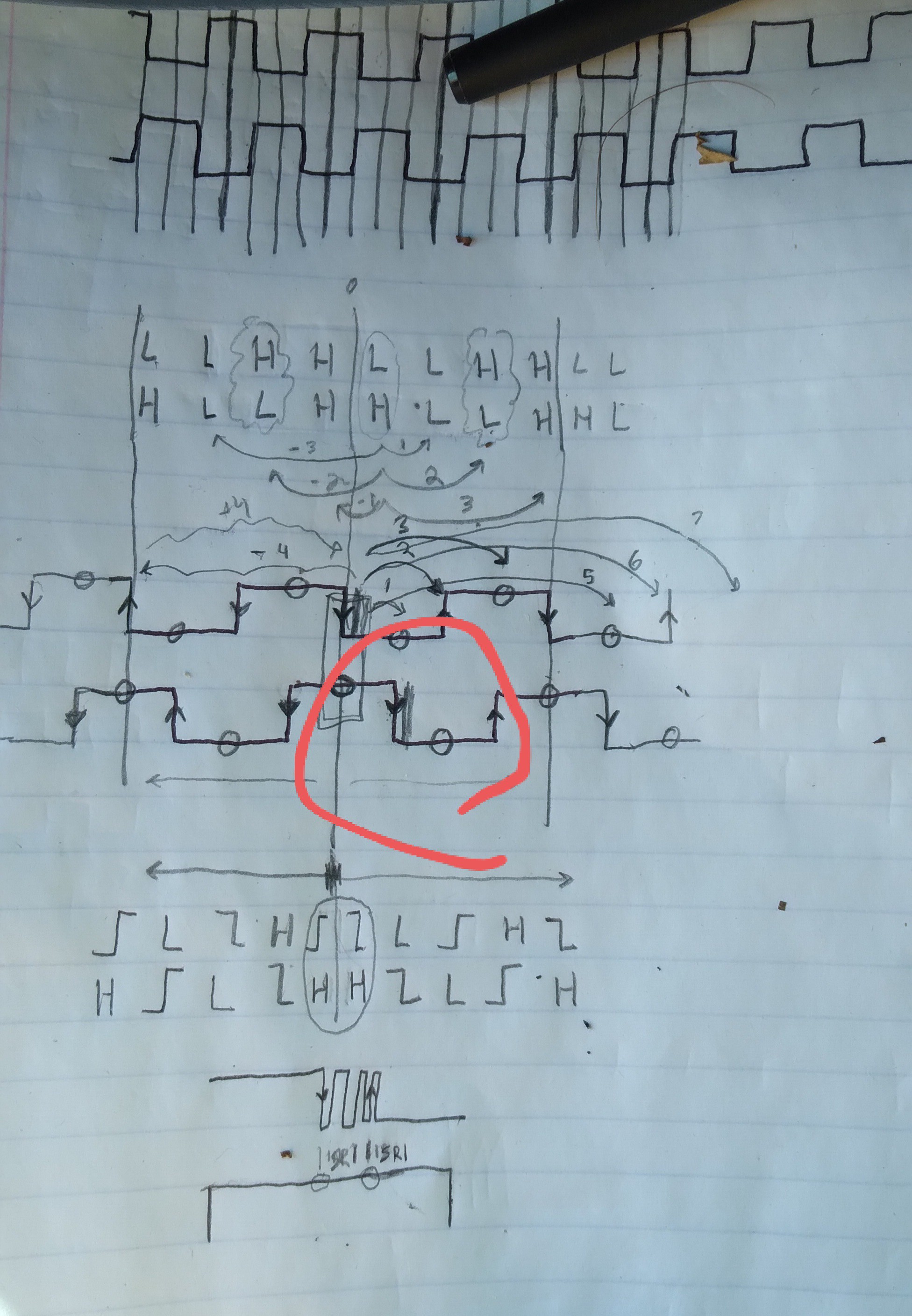
NOPE.
.
So, still, we have to watch *every* quadrature edge.
Discussions
Become a Hackaday.io Member
Create an account to leave a comment. Already have an account? Log In.