 Arkadi
Raspberry Pi Pins and Connections
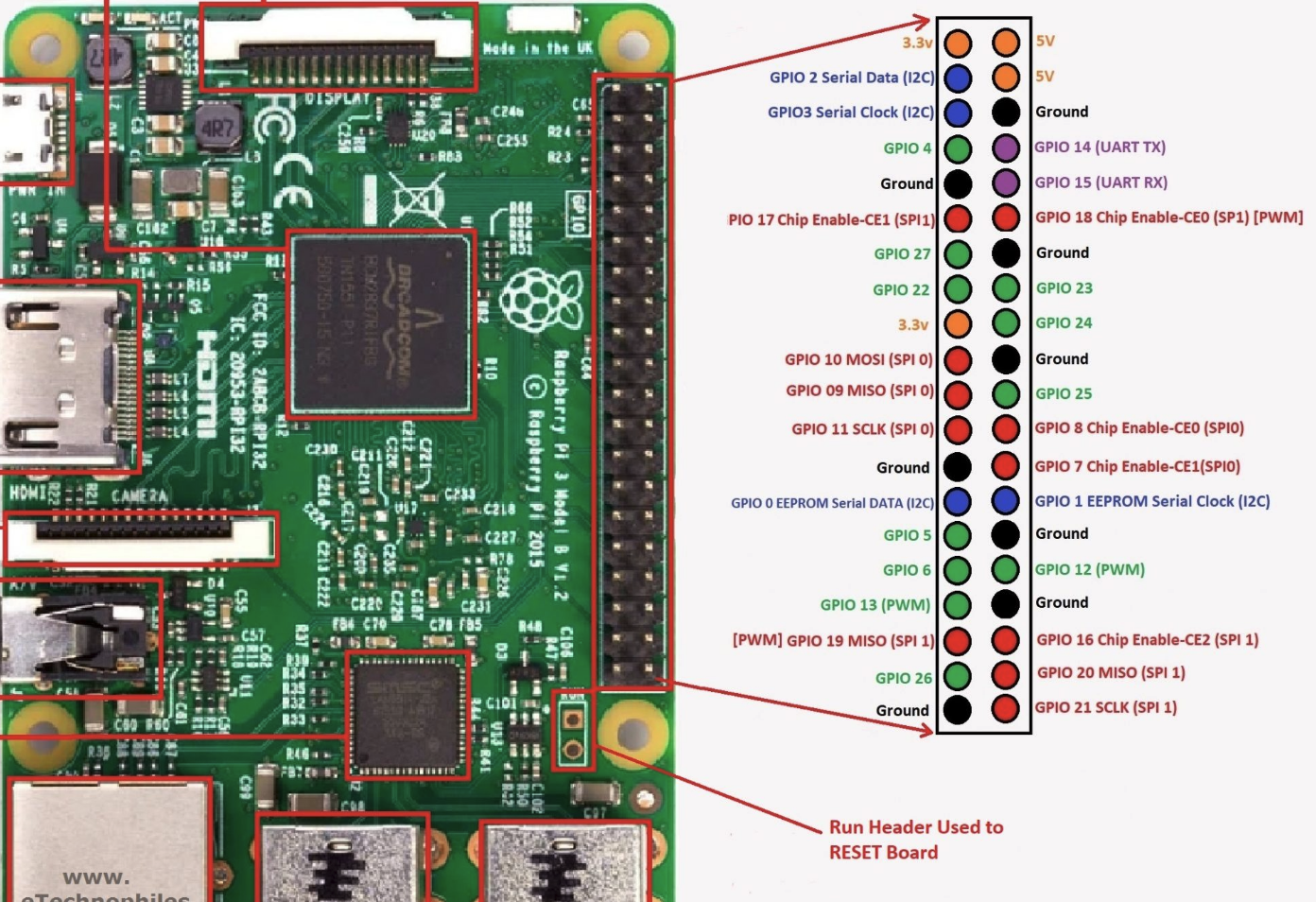
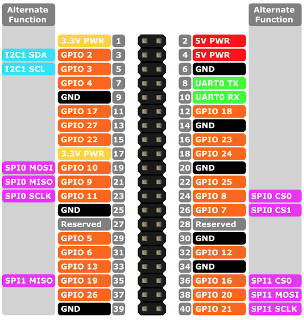
The Raspberry Pi pinout shows which pins correspond to what functionality. I connected pin 1 (3.3 V) to the + rail of my breadboard and pin 6 (ground) to the - rail of my breadboard. The GPIO pins you choose to use do not matter but in my case I dedicated pins 7, 11, 13, and 15 to one display and pins 31, 33, 35, and 37 to another. The first set of Pi pins are connected to the the first decoder IC pins as follows: GPIO 7 -> IC 6, GPIO 11 -> IC 2, GPIO 13 -> IC 1, and GPIO 15 -> IC 7. The second set of the Pi pins are connected to the second decoder IC pins as follows: GPIO 31 -> IC 6, GPIO 33 -> IC 2, GPIO 35 -> IC 1, GPIO 37 -> IC 7.
SN74LS47N and 7 Segment Display Circuit Connection
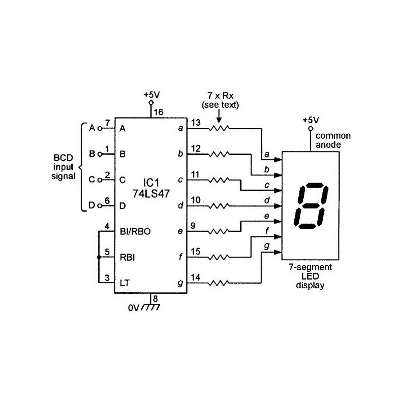
*IMPORTANT* (When making pin connections, with the divot pointed upwards, the left side going from top to bottom will be pins 1 through 8 and the right side of the IC from bottom to top will be pins 9 through 16. The schematic pin numbers are simply grouped in this way in order to better clarify what groups the pins belong to. It is important to adhere to the pin numbers)
Connect the SN74LS47N to the 7 segment display as shown. To keep things tidy and neater in terms of connections and minimize GPIO port usage and thus wire usage we will use the decoder IC so that we can use 4 GPIO inputs to drive an otherwise 7 input display. (This means that for 4 different inputs we get 7 different outputs.) We will use pins 1, 2, 6, and 7 (or A B C D) to take in digital high and low signals in order to represent information in the form of digits (0 - 9) on the display. Pin 16 is the power pin and is connected to 3.3V or 5V and pin 8 is ground. Each output pin (pins 9 - 15 ; a - g) will require its own resistor. A resistor value of 100 to 1kOhm will work fine but it should be noted that the lower the resistor value the higher the current and thus the brighter the led segment will be. There will be two of these IC decoders for two individual displays.
SN74LS47N Truth Table
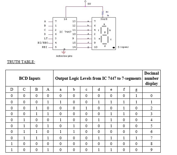
This truth table shows the corresponding 0 - 9 numeric representation output on the 7 seven segment display for given HIGH and LOW input values (BCD Input column). What this means is that encoded into the IC is the logic for getting a certain 7 bit numerical output (number seen on display) based on the 4 bit input.
T = True
F = False

table = {'0': [F, F, F, F],
         '1': [F, F, F, T],
         '2': [F, F, T, F],
         '3': [F, F, T, T],
         '4': [F, T, F, F],
         '5': [F, T, F, T],
         '6': [F, T, T, F],
         '7': [F, T, T, T],
         '8': [T, F, F, F],
         '9': [T, F, F, T]
         }
In the code we implement the logic needed to run the decoder IC via a Python dictionary so that during temperature data parsing in the program when a certain numerical value is attained, the corresponding truth table sequence is called and pushed to the IC via GPIO pins.
The Code
Code to be run on an IDE to ensure everything is in working order: https://github.com/greentextterminal/Hardware-Software_Thermometer/blob/main/HST_IDECode
Raspberry Pi version of the code when circuit is implemented: https://github.com/greentextterminal/Hardware-Software_Thermometer/blob/main/HST_RaspberryPiCode
In the code, there is a try, except, finally structure. In the finally block the RPi.GPIO.cleanup function is called. This is an important step since the function redesignates the pins to open or unassigned for the next time when they are used. If the pins were previously set to an input or output, the Raspberry Pi "remembers" the assignment and if you were to use the Pi and those pins again for something else you may run the risk of short circuiting and damaging your circuit or Pi. For this reason the cleanup function is called. In my program I also added to the finally block text which prints to the console indicating that the cleanup function was called. Confirm you cleanup the pin assignment with the print statement from the code as well as making sure an error such as this one does not appear when you run a program on the Pi.

(Credit to Jeff Everhart and his excellent article on covering the GPIO error handling, why it's important, and a good way to do so.
https://jeffreyeverhart.com/2016/08/21/using-cleanup-method-rpi-gpio-raspberry-pi-tutorial/ )