 Mrinnovative
DIY-MINI-BLDC-motor-winder

Hello friends I have made a mini stator winding machine using Arduino, this is just a prototype this machine is not accurate. This just give us idea how stator winding machine can work. In this project I have used two stepper motor one used to rotate wire arm and one will rotate the stator. Copper wire passed from the hollow tube and when wire arm rotate it wind coil to the pole. alternate pole windings are clockwise and anticlockwise respectively. I have added a reciprocating mechanism off camera this will help to wind coil with some width otherwise arm will wind coil on a single point.
COMPONENT USED
Arduino Nano A4988 stepper driver 2 x Nemw 17 stepper motor 3D Printed parts 5mm OD hollow tube copper wire timing belt timing pulley Nextion HMI
PROCEDURE


First I have made base for machine from the wooden sheet. its 12mm thick wodeen sheet the measurement of the base sheet is 100 x 250 mm I used jigsaw machine to cut the wooden sheet and at last I have added 4 rubber legs to the bottom o the machine

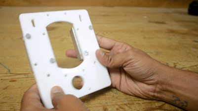
then I 3d printed some parts to hold bearing and this part will fixed at front and back of the stepper motor I have used white PLA filament with 20 % infill to print this part I printed the part in my artillery genius 3d printer
Now I bring one NEMA 17 stepper motor whose specification are as following
Step Angle: 1.8 ° Current: 1.2 A/Phase Holding Torque: 4.2 kg-cm Detent torque: 2.2 N.cm (Maximum) Lead Wires: 4 Shaft diameter: 5 mm
I placed the bearing holder 3d printed part in front and back of the stepper motor
Now I bring the 5mm OD hollow SS tube this is the one of the most important part of the machine copper wire passed through this tube and wind on to the pole
I cut it in reuired length with the help of angle grinder and polished it using my mini lathe machine

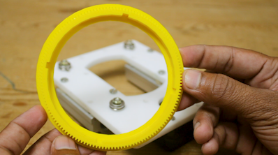
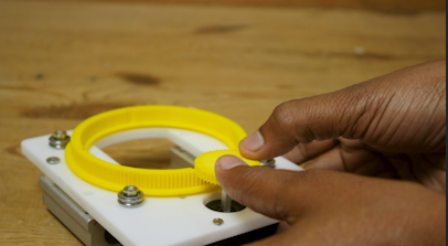
Now I assemble the tube assembly as shown in image. I first place a timing pulley on to the shaft of stepper motor and I also placed one another timming pulley to the hollow tube and connect both of the pulley with the help of closed loop timing belt in this way when stepper motor rotate the tube is also rotate
I have used my multipurpose PCB for Arduino based resistor reel cutting machine project. If you want to have this PCB Please find the Gerber file from the link below so that you can order your own PCB I suggest you JLCPCB.COM to choose your PCB manufacturer they really have very good service and low price Multipurpose PCB link https://oshwlab.com/sharmaz747/multipurpose-pcb
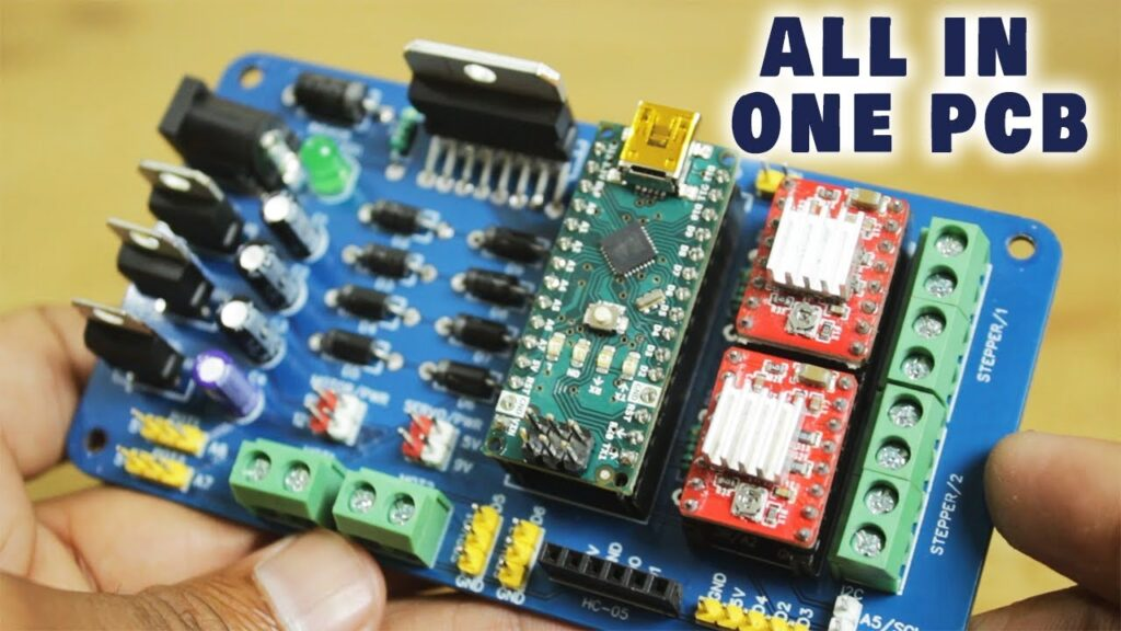


Making such projects without PCB is night mare yes trust me you cannot get wanted result and professional touch in your project if you ignore PCB So some days back I have developed my Multipurpose PCB. This PCB is used to build wide range of arduino projects
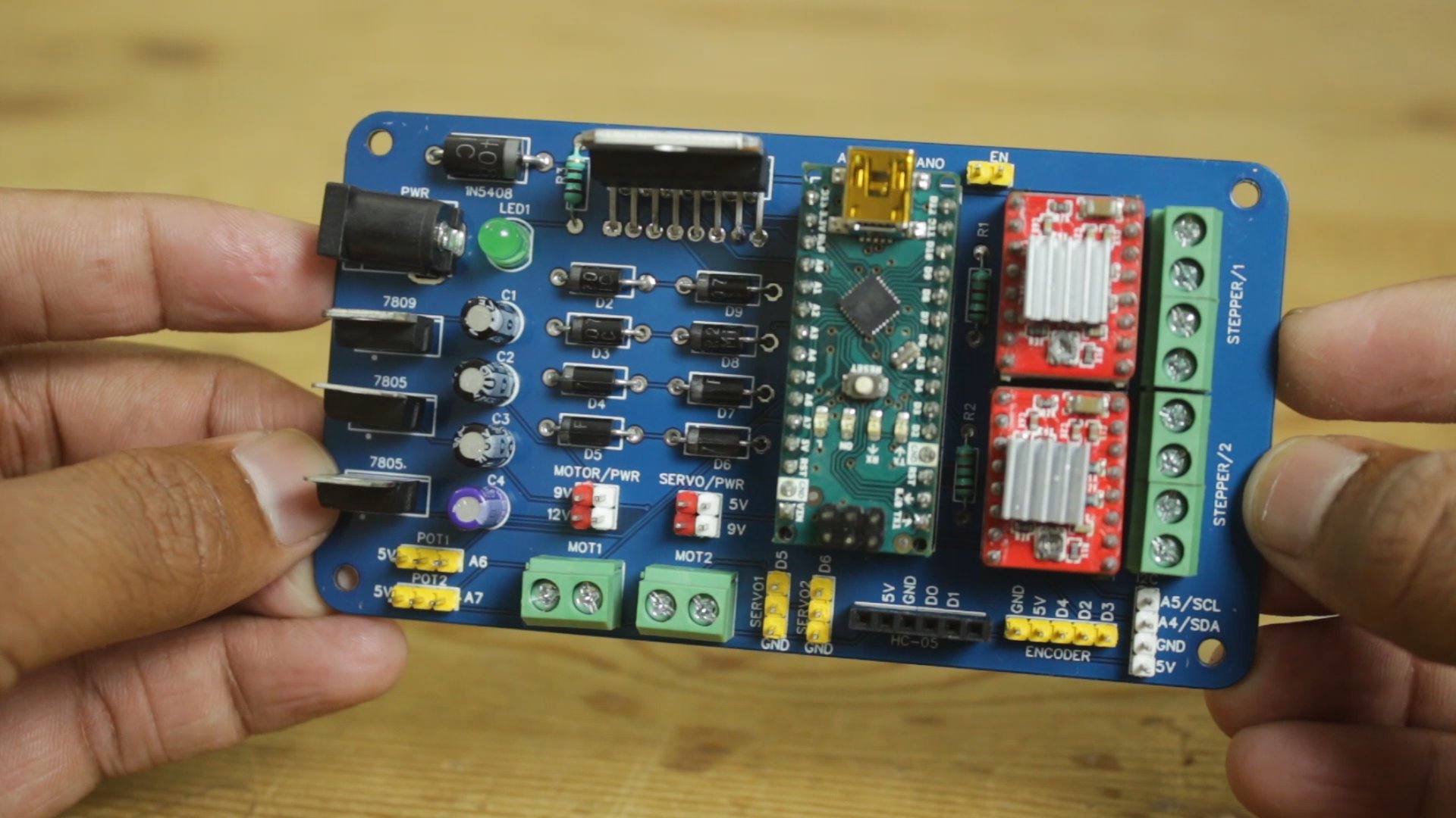
followings are the some features of PCB
- Wide range of power input 9V to 24V DC
- Cross polarity protection
- DC motor voltage selection 9V or 12 V DC
- Servo motor voltage selection 5V or 9V DC
- Manual microstepping setting for stepper motor
- Power indication LED
- L298N IC for heavier DC motor
- ON board 5V and 9V regulator no need to arrange different power sources
- Header pins and screw terminals for easy connections
List of the Components you can connect to the PCB
- 2 DC motor ( 9V to 24V DC)
- 2 Potentiometer
- 2 Servo motors ( 5V to 9V DC)
- 1 Serial device (BT module, HMI, Communication module, RX, TX)
- 1 Encoder (2 interrupt pin & 1 PB pin)
- 1 I2C device (SCL/SDA Device, display, MPU6050 etc)
- 2 Stepper motors

I have design circuit and PCB in easyEDA and ordered PCB from JLCPCB
This is the link of PCB editabl file
If you seriously need quality PCB quickly in your hand then you must have to try JLCPCB PCB manufacturing service. They have Special offer of $2 for 1-4 Layer PCBs, free SMT assembly monthly. If you get yourself registered today at JLCPCB you get coupons worth of 30$ from JLCPCB.
SMT Assembly service of JLCPCB.com is cherry on top now get your PCB fully assembled and save your time and money Select components for your PCB from there Parts Library of 200k+ in-stock components they are offering $30 valued New User coupons & $24 SMT coupons every month $8.00 setup fee, and $0.0017 per joint
Now no need to order components separately for you PCB and get free from stress of soldering them on PCB just try PCB SMT assembly service and get you PCB with components pre assembled and ready for the project
👉 Try PCBA service of JLCPCB.com and save your time and money, get PCB ready for project, 200K+ components in library of JLCPCB.com as well as 3rd party parts to choose from. Assembly will support 10M+ parts from Digikey, mouser
👉 $30 valued New User coupons
👉 $24 SMT coupons every month
For more detials & offers please visit JLCPCB.com


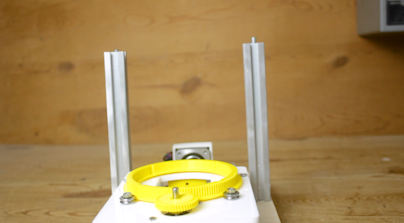
Now I placed a 3D Printed wire guider to the hollow tube and I also inserted a shaft coupler to the second stepper motor


Nextion Enhanced NX3224K028 is a powerful 2.8” HMI TFT display, with 16MB Flash data storage space, 1024 bytes EEPROM, 3584 bytes RAM. With GPIO supported, now customers can use Nextion to control external devices.
Nextion is a seamless Human Machine Interface (HMI) solution that provides a control and visualization interface between a human and a process, machine, application or appliance. Nextion is mainly applied to the Internet of thing (IoT) or the consumer electronics field. It is the best solution to replace the traditional LCD and LED Nixie tube.

In this way our machine construction is completed
Arduino code
#include <Stepper.h>
#include <Arduino.h>
#include "BasicStepperDriver.h"
#include "MultiDriver.h"
#include "SyncDriver.h"
#include <SoftwareSerial.h>
SoftwareSerial mySerial(2, 3); // RX, TX
float A = 0;
float B = 0;
int state = 0;
String message;
int QTY, numMessages, endBytes;
byte inByte;
int flag = 0;
int lastflag = 0;
int C=0;


#define MOTOR_STEPS 200
#define DIR_X 14
#define STEP_X 15
#define DIR_Y 16
#define STEP_Y 17
#define MICROSTEPS 16
#define MOTOR_X_RPM 50
#define MOTOR_Y_RPM 350
#define pause 12

BasicStepperDriver stepperX(200, DIR_X, STEP_X);
BasicStepperDriver stepperY(160, DIR_Y, STEP_Y);
SyncDriver controller(stepperX, stepperY);


void setup()
{  numMessages, endBytes = 0;    pinMode (pause,OUTPUT);  Serial.begin(9600);  mySerial.begin(9600);  stepperX.begin(MOTOR_X_RPM, MICROSTEPS);    stepperY.begin(MOTOR_Y_RPM, MICROSTEPS);    digitalWrite (pause,HIGH);  delay(500);  }

void loop()
{  data();    if (A > 0 && B > 0) {    delay(1000);

C = 360/A;
digitalWrite (pause,LOW);
    for (int i = 0; i < A; i++) {      delay(1000);

if (flag == 0){
       for (int i = 0; i < B; i++){  controller.rotate(0, 360);   }  flag = 1; }


else {  for (int i = 0; i < B; i++){  controller.rotate(0, -360);   }   flag = 0;
}
 if (i<A-1){

delay(1000); controller.rotate(C, 0 );
 }         }         A=0;    B=0;
  }
digitalWrite (pause,HIGH);  }
  void data() {    if (state < 1) {      if (numMessages == 1) { //Did we receive the anticipated number of messages? In this case we only want to receive 1 message.        A = QTY;        Serial.println(A);//See what the important message is that the Arduino receives from the Nextion        numMessages = 0; //Now that the entire set of data is received, reset the number of messages received        state = 1;      }    }
    if (state > 0) {      if (numMessages == 1) { //Did we receive the anticipated number of messages? In this case we only want to receive 1 message.        B = QTY;        Serial.println(B);//See what the important message is that the Arduino receives from the Nextion        numMessages = 0; //Now that the entire set of data is received, reset the number of messages received        state = 0;      }    }


    if (mySerial.available()) { //Is data coming through the serial from the Nextion?      inByte = mySerial.read();
      // Serial.println(inByte); //See the data as it comes in
      if (inByte > 47 && inByte < 58) { //Is it data that we want to use?        message.concat(char(inByte)); //Cast the decimal number to a character and add it to the message      }      else if (inByte == 255) { //Is it an end byte?        endBytes = endBytes + 1; //If so, count it as an end byte.      }
      if (inByte == 255 && endBytes == 3) { //Is it the 3rd (aka last) end byte?        QTY = message.toInt(); //Because we have now received the whole message, we can save it in a variable.        message = ""; //We received the whole message, so now we can clear the variable to avoid getting mixed messages.        endBytes = 0; //We received the whole message, we need to clear the variable so that we can identify the next message's end        numMessages  = numMessages + 1; //We received the whole message, therefore we increment the number of messages received.
        //Now lets test if it worked by playing around with the variable.
      }    }  }
