The Bright Bulb consists of two main components: the sensor array, and the bulb.
BULB
The bulb is composed of an outer housing, and a PCB equipped with LEDs and an ESP-32 to handle the smart functions of the light.
Bulb Housing
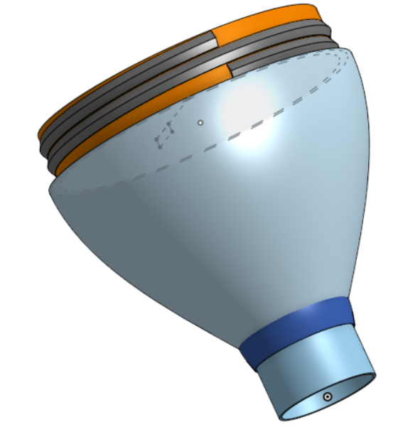
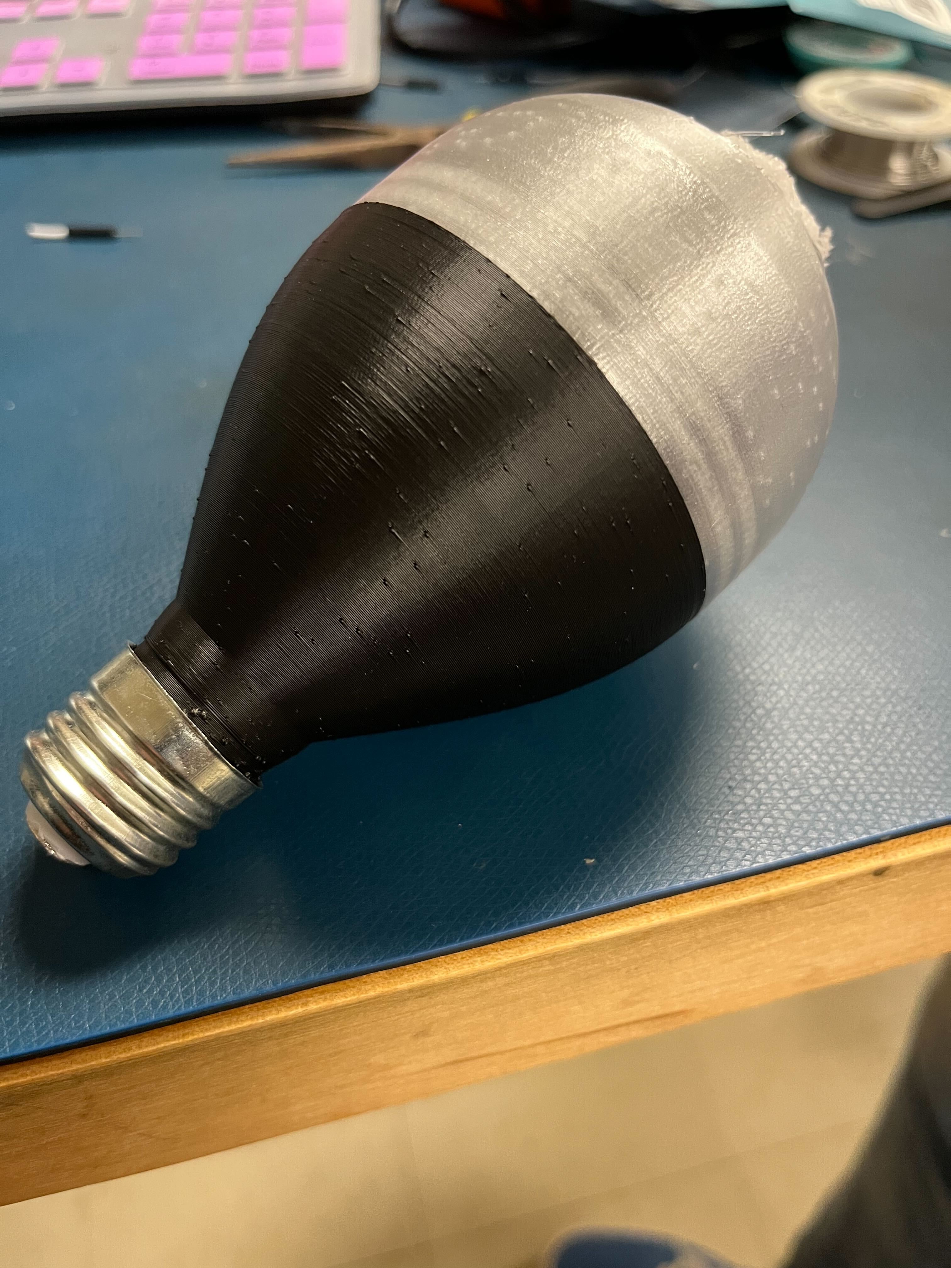
We designed the outer housing using OnShape (.stl files included under "files"), and 3D printed it in two parts
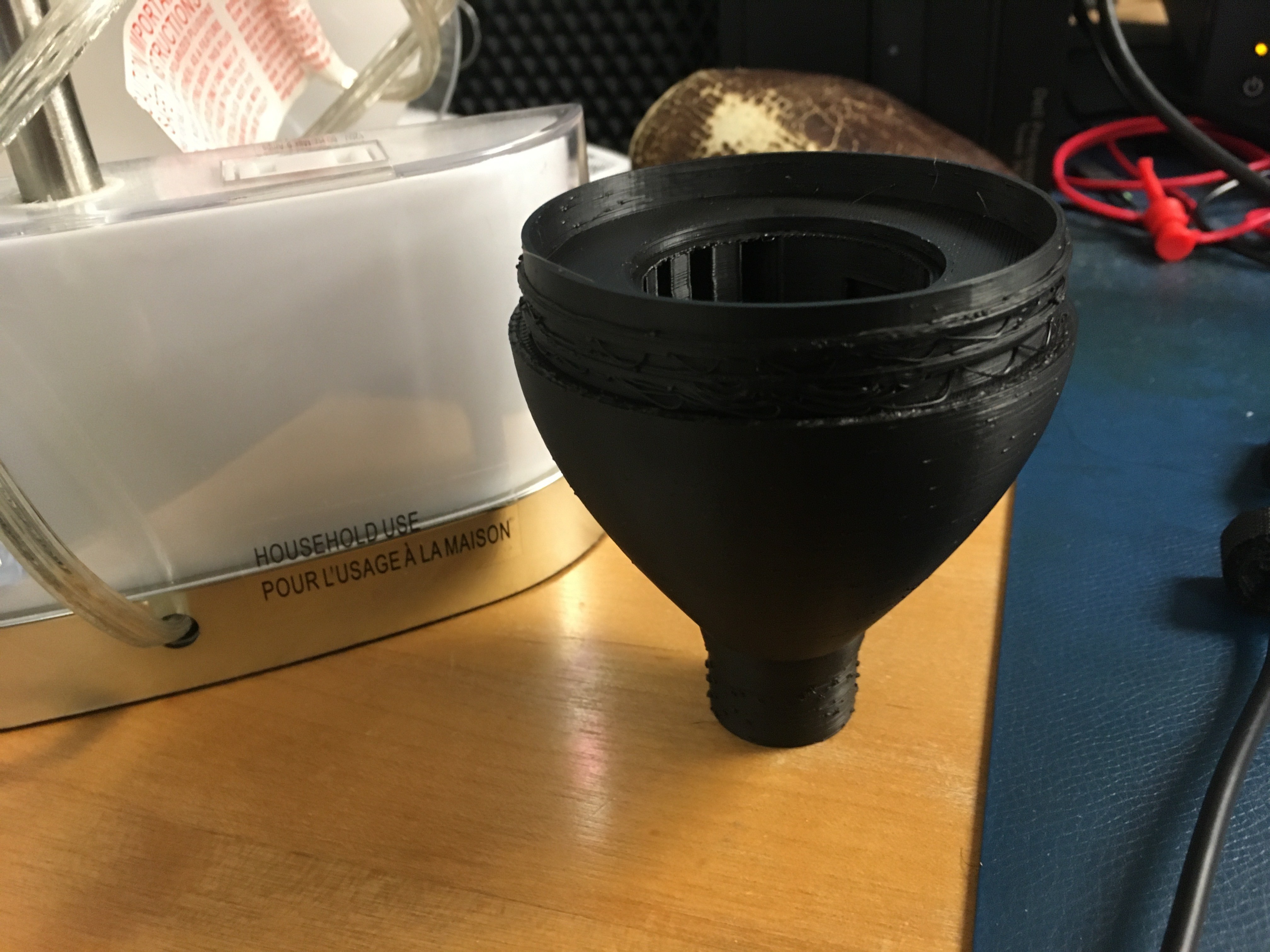
The bottom part was printed using an opaque plastic. It starts out as a a 0.95" (outer diameter) cylinder, which a metal light bulb socket is crimped around. The cylinder extends upwards for 0.5", and then expands out to an inner diameter of 1" over 0.25" of height. The part then steadily expands in inner diameter from 1" to 2.75" over 2.25" of height. Upon reaching 2.75" in inner diameter, the part extends up 0.75" as a cylinder. It also has a perimeter shelf 0.5" thick and 2mm tall, located 0.25 inches from the top of the part. The PCB is attached to this shelf via the screw holes around the edges of the PCB.
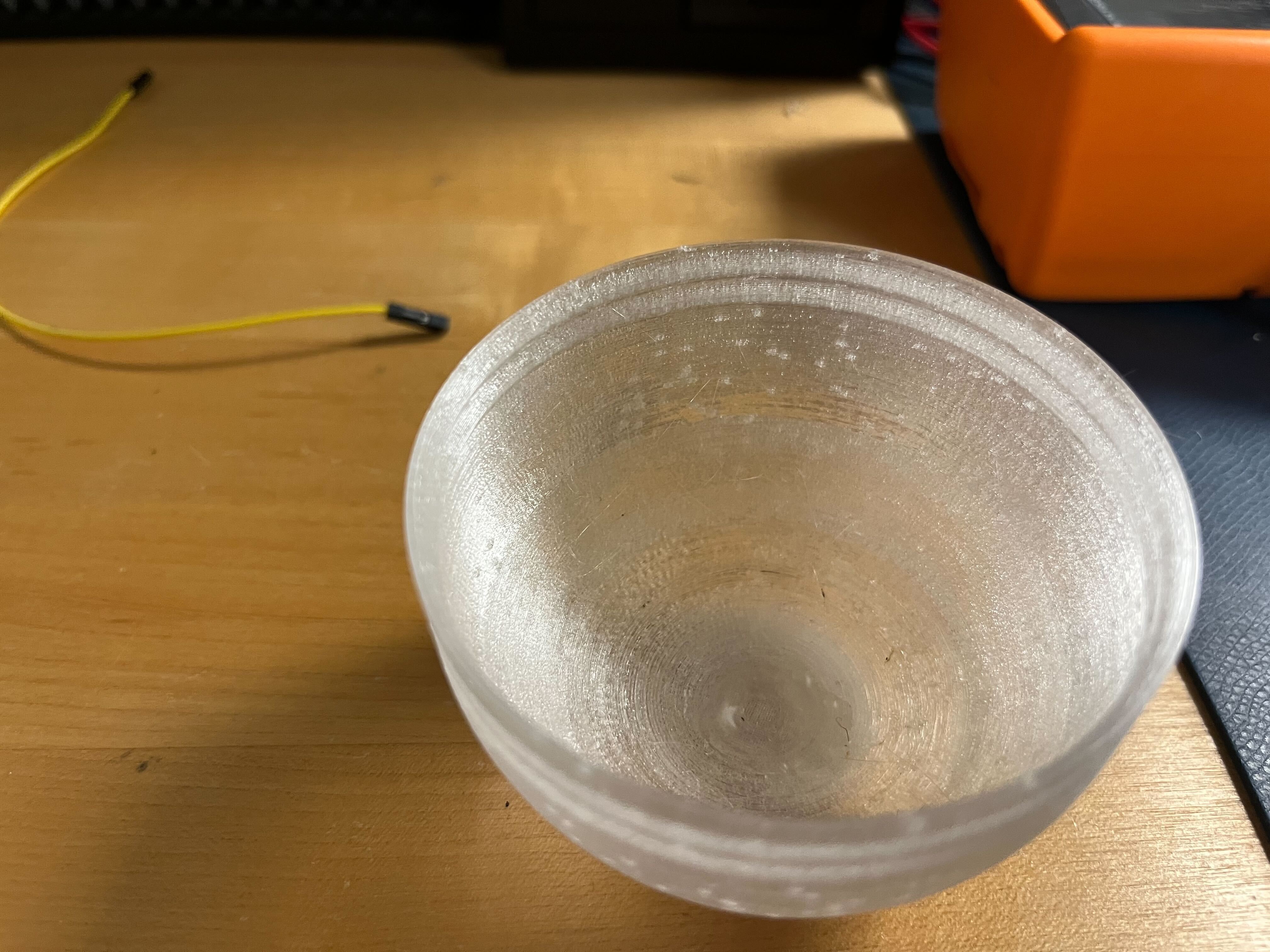
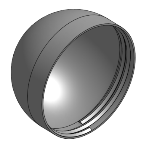
The top part was printed using a translucent plastic to diffuse the light from the PCB. It is a 2.75" diameter hemisphere, that terminates in a 0.75" long cylinder.
The two parts are connected like a screw-cap on a bottle, with the top part acting as the cap. The teeth of the screws are isosceles triangles with base length of 4mm and a height of 1mm, wound in a CW spiral such that there are two complete revolutions every 8.5mm. Both parts are 1mm thick.
PCB
As previously stated, the hardware for this project is divided into two boards: an external sensor array and the board within the bulb. Due to the size constraint of fitting the board into the bulb housing, we decided to design and print a PCB for the bulb board. We did this using EAGLE, and our .sch and .brd files are included in the "files" section. Below is a picture of our assembled PCB.
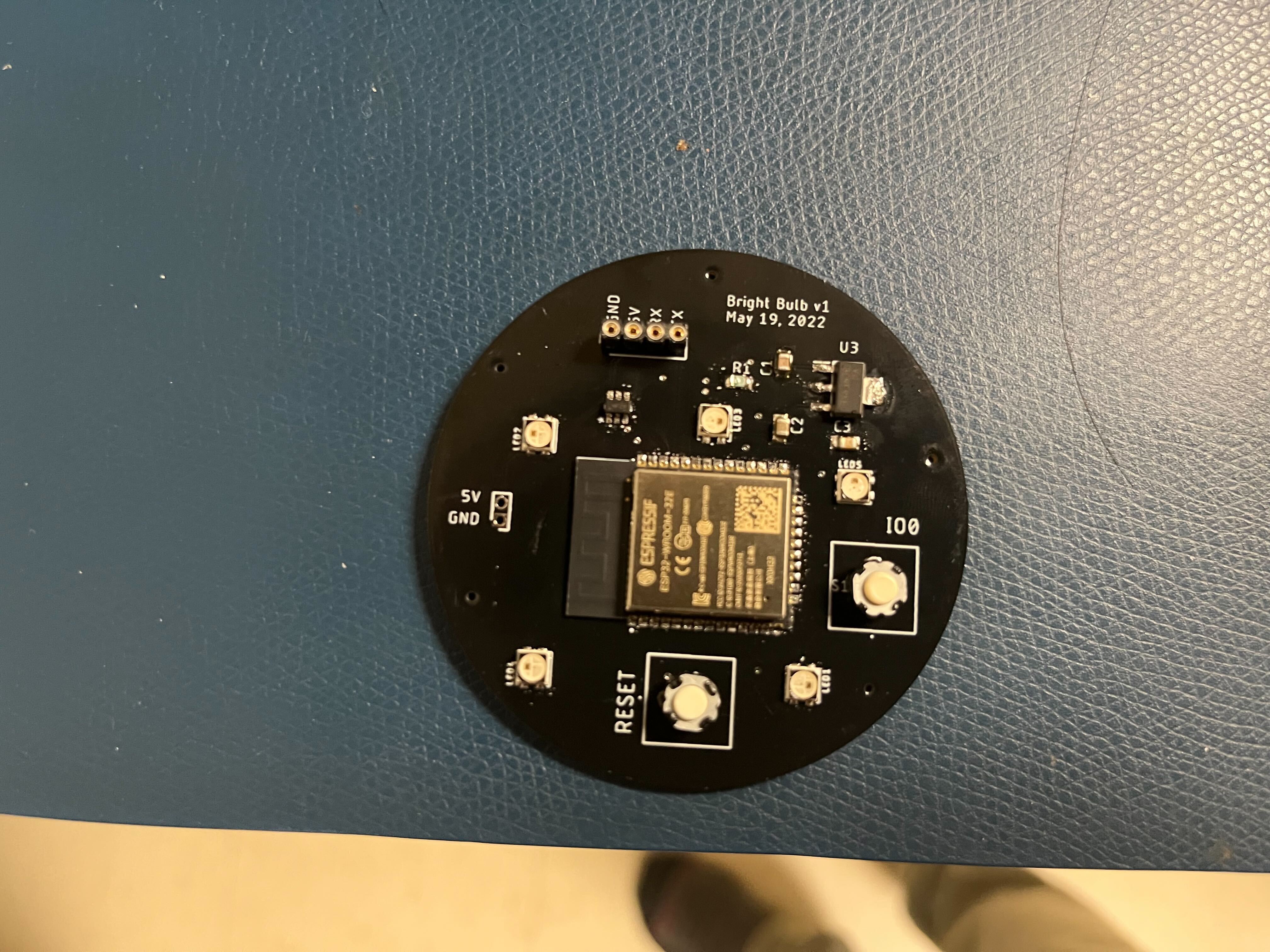
When fully assembled within the bulb housing, our PCB is supplied power from the output of an AC to DC buck converter (5V, 1A output) to the power input on the left side of the board. We then have a linear regulator (5V to 3V3) that supplies the 3V3 components on the board. The main component of our PCB is the ESP-32. This chip allows for wireless communication to the sensor board through the ESP-NOW protocol, and drives the five neopixel LEDs by way of a logic translator IC. It also sets up our web server which is talked about in detail further below.
In order to upload software to our ESP-32 chip, we added the buttons RESET and IO0 as well as the connector at the top of the board. The connector allows us to attach a USB to UART converter to the board to upload code, and the buttons are required for the board to boot into download mode (this occurs when the user resets the chip while holding IO0 low).
ESP-32 Code
The bulb will have code to receive the communications from the sensors and from the web server, and be able to turn the light on and off.
Wireless Communications
Each chip is equipped with code that is able to wirelessly communicate with each other using ESP-NOW. This is a one-way communication from the sensor board to the bulb. When receiving data, if the bulb is in "automatic mode," it will turn on the lights and reset a timer each time it receives data from the sensor board. After it has not received data for a user decided amount of time, meaning the sensors no longer detect motion, the light will once again turn off.
NOTE: In order to perform wireless communication, the MAC must be added to the code:
const uint8_t broadcastAddress[] = // MAC Address for sensor board here
// in form of: [0x01, 0x02, 0x03, 0x04, 0x05]
Web server
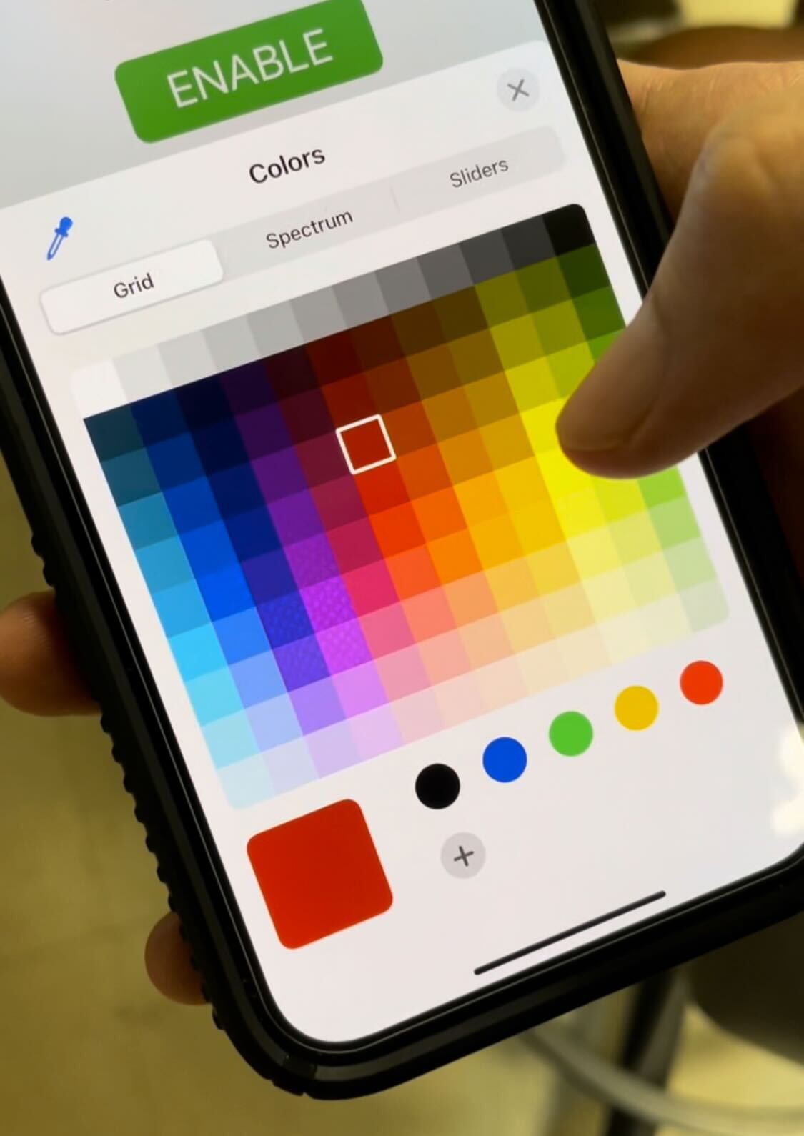
The ESP-32 is also used to host the web server through which users can change the settings of their light bulb. The web server is asynchronous, using a locally hosted webserver on the ESP32. It is formatted using html, and data entered by the user is communicated to the ESP-32 using xml.
The current features that the web server contains is as follows:
- Manual ON / OFF switch
- Enable / Disable automatic behavior switch
- Brightness slider
- Color wheel (with optional direct RGB value input)
- Timer setter
NOTE: In order for the server to be hosted, the wifi information must be updated in the code:
const char* ssid = // Name of wifi
char* password = // Password for wifi, could be unnecessary
LED Control
The design utilizes the Adafruit NeoPixel LED's and the libraries provide. The light bulb's chip receives a 16-bit number from the web server and converts into a RGB value to display. The following formula is called in the "loop()" part of the bulbBoard code (.zip file attached):
void turnOnLights(unsigned long color, float brightness){
  //unsigned long outputColor = applybrightness(color, brightness);
  for(int i=0;i<=LED_COUNT;i++){
    strip.setPixelColor(i,color);
  }
  strip.setBrightness(255*brightness);  // brightness is between 0 and 1
  strip.show();
}
The values color and brightness are being acquired from the Web Server Code.
"Automatic Mode"
The Bulb comes equipped with an Automatic Mode that can be enabled and disabled from the web server. When Automatic Mode is disabled, the user has full control over when the lights turn on and off. The external sensors have no control over whether the lights are on or off.
When Automatic Mode is enabled, the sensors outputs will determine whether the light is on or off. When the Bulb Board receives data from the sensors, it is dark and is detecting movement. When it receives this data, the lights turn on and a timer is started.
// Function is Called Everytime Data is Received
void OnDataRecv(const uint8_t * mac, const uint8_t *incomingLight, int len) {
  memcpy(&light_status, incomingLight, sizeof(light_status));
  Serial.print("Bytes received: ");
  Serial.println(len);
  set_motion(1);
  start = millis();
}
As long as the bulb is receiving data it will continually reset the timer. If it does not receive data and the timer runs for the user determined length, the lights will once again power off. However, if the bulb receives any data in while the timer is running, the timer will once again reset.
Sensor Array
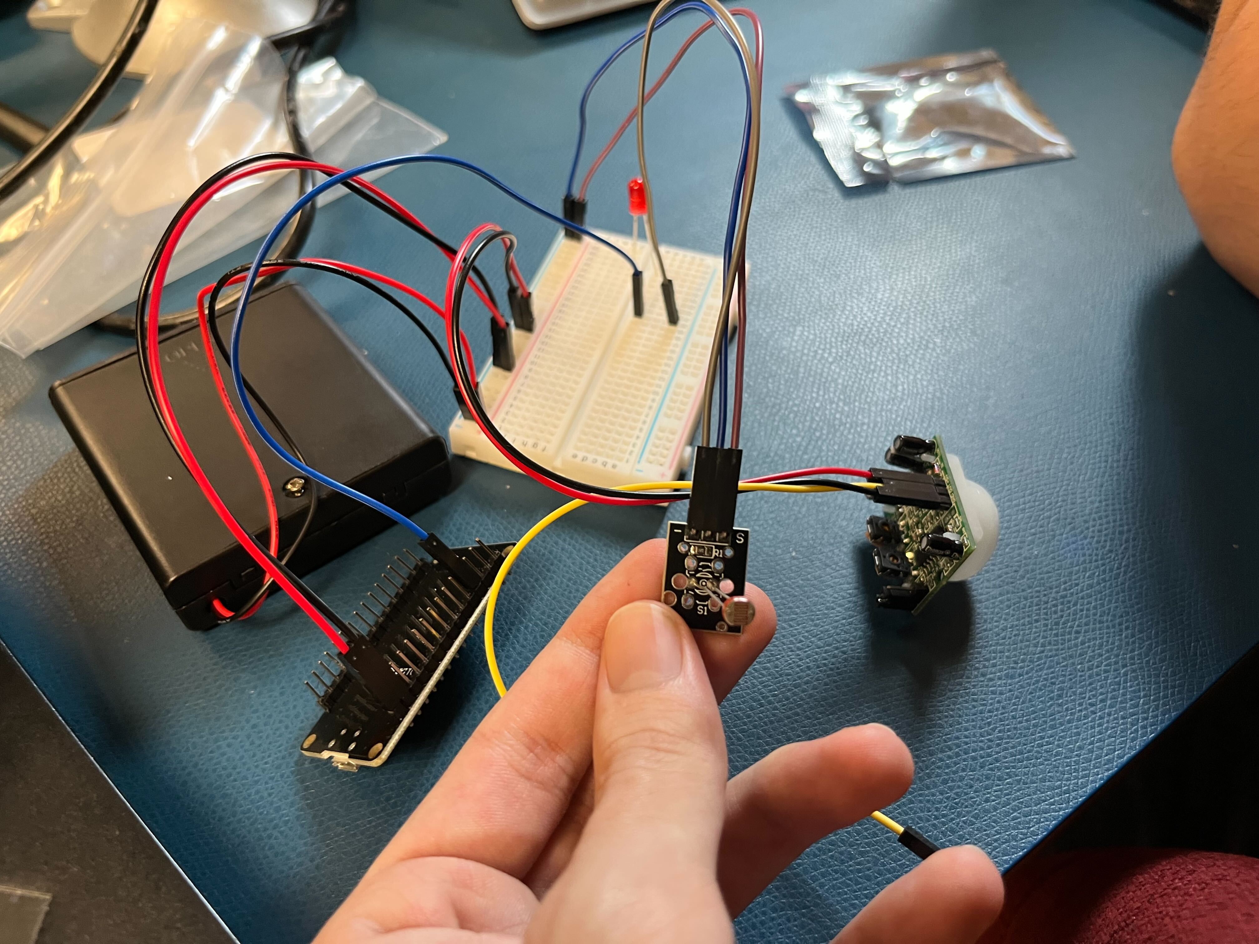
The sensor array is currently held on a breadboard, and instead of a standalone ESP-32 chip, it currently uses a breakout board.
Circuitry
The sensor array currently has two sensors: a photoresistor to measure the ambient light level, and a PIR motion detector. The photoresistor has a high output when the surroundings are well lit, and a low output when they are dark. The PIR motion detector swings high whenever it detects motion in a 20ft cone in front of it. We turned the PIR so that it is fairly sensitive, and it will continue to detect motion in a room if there are people in it due to their slight movements, even if at rest. Both of these outputs are fed to input pins on the ESP-32 devboard, where they are then interpreted.
The entire circuit, including all sensors and the ESP-32 devboard, is powered using 4 AA batteries.
ESP-32 Code
The code for the Sensor Array is designed to read the sensors, wirelessly communicate with the bulb board, and wake up the board or put it to sleep when necessary.
Reading the Sensors
The sensor board is programmed to be reading the outputs of the PIR motion sensor and the photoresistor. The photoresistor is an analog input and determines how dark the room is. Whenever the value read by the photoresistor goes below a specific threshold, a variable is changed to indicate that it is "dark."
The PIR motion sensor is being read to detect whether or not there is motion. If there is motion and it is not below the light threshold, nothing happens. However, when there is motion and it is below the light threshold, the board wirelessly communicates with the Bulb Board.
Wireless Communication
Similar to the bulb, the sensor board is coded to use ESP-NOW to wirelessly communicate. Whenever the light threshold is met and motion is detected, the wireless communication is sent to the bulb. Then as long as the sensors are detecting motion, data will constantly be sent. This is to ensure that the light stays on as long as there is motion.
NOTE: In order to communicate with the bulb the MAC address must be added to the code:
uint8_t broadcastAddress[] = // MAC  address of bulb board here
// in form of: [0x01, 0x02, 0x03, 0x04, 0x05]
Deep Sleep Mode
In order for the sensor board to operate on battery power we made sure to put it into deep sleep mode for the majority of its time of activity. Whenever it is not detecting any motion the device is in deep sleep mode and is drawing very little current. Whenever it detects motion it then checks if it is dark, if not then it goes back to sleep.
If it detects motion and it is dark, then it wakes up for the duration that it detects motion. It won't go back to sleep until it stops detecting motion. This is to ensure that data can be sent and the timer can be reset as it needs to be.