Hulk
HulkIn my last tutorial I created a NodeMCU based Duino Coin Miner. It is an awesome little miner that sits on my desk and mines few cents a day.
However, adding these miners to my home network choked my WiFi router. Home Appliances and Smart Devices connected to the router constantly started dropping off. To my understanding, most of the wireless routers and access points can support upto 250 devices connected at once. So, what's happening here?
To clarify my doubts I called my ISP. The answer they gave was absolutely shocking. "ONLY 30 devices can successfully connect and exchange data via their router at any given time". Bloody hell!!
So, to overcome this limitation I added another router to the network to scale up the load.
But, I was not happy with this solution. So, I did a bit of research and found this "NRF24L01 RF Transceiver Module" which I can use to create a mesh of wirelessly connected microcontrollers.
In this tutorial, I am going to show you guys how to use this transceiver module to add wireless communication between two or more Arduino boards. I will be using this module for many of my upcoming home automation projects. Bang Problem solved..
What is a NRF24L01 RF Transceiver Module?

So far, I have always used WiFi for wireless communication between microcontrollers. While this is easy enough to do, it is not exactly suitable for battery operated nodes. WiFi modules consume a lot of current when transmitting data plus they also have a slight delay when initiating the transmission as the module has to first connect to the WiFi network.
After getting crippled by the abilities of my wireless router, I found this cheap, very popular and widely used "RF Transceiver Module" which you can hook up to any microcontroller (MCU). This module is called a RF transceiver because a single module can work both as a transmitter and a receiver.
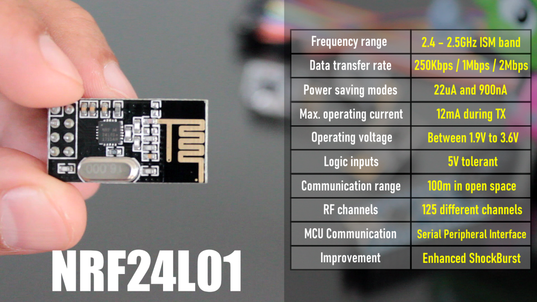
- The module operates at a frequency of 2.4GHz, which is one of the ISM band which means it is open to use in most of the countries around the World.
- Data transfer rate is between 250kbps to 2Mbps baud.
- Power consumption? This module is designed for ultra low power wireless applications. It has 2 power saving modes operating at 22uA Standby-I mode and 900nA in power down mode - which makes these modules suitable for battery operated nodes. The high air data rate combined with two power saving modes makes the nRF24L01 module very suitable for ultra low power designs. The power consumption of this module is just around 12 milliamps during transmission (TX) which is even lower than a single led.
- Operating voltage is between 1.9V to 3.6V. All other pins on this board are 5V tolerant making it easy to connect to an Arduino without using a logic level converter. It has an integrated (on chip) voltage regulator.
- The Range of this module as per its datasheet is 100m but it works up to 50 to 60 meters in real world conditions.
- The module has 125 independent RF channels giving the possibility to have a network of "125 independently working modems" in one place. Each channel can have up to "6 addresses or 6 data pipes" or in other words, each unit can communicate with up to 6 other units at the same time (1:6 star networks).
- The module is configured and operated through a Serial Peripheral Interface (SPI).
- It uses Enhanced ShockBurst™ for automatic packet assembly and timing, automatic acknowledgement and retransmission of packets. Enhanced ShockBurst™ enables the implementation of ultra low power, high performance communication with low cost host microcontrollers. The features enable significant improvements of power efficiency for bi-directional and uni-directional systems, without adding complexity on the host controller side.

The module used in this video has an in-built PCB antenna making it compact. However, you can also buy a variant that supports an external antenna allowing much higher range of about 1000M in line of sight.

 R. Scott Coppersmith
 Cristian Dobre