The unit consists of two distinct and independent sections: a PV driven Pulse charger and Pump Control. They share a fused (F100) connection to a 12V LFP or LA battery. C110 provides bulk capacitance to protect the Pulse Charger when no battery is present and the PV panel is energized. Battery drain during dark or fault conditions (e.g. low battery voltage, pump over-current) is ~ 23uA.
Pulse Charger
The Pulse Charger is responsible for charging the battery. At battery voltages below the set threshold for a charged battery (13.6~13.8V), the PV panel is connected directly to the battery. When the battery reaches full charge the panel is disconnected until the battery voltage drops below the threshold. This process repeats at a varying frequency and duty cycle based on the battery's State Of Charge (SOC). Hence the name Pulse Charger. Maximum Power Point Tracking (MPPT) is not possible with this design.
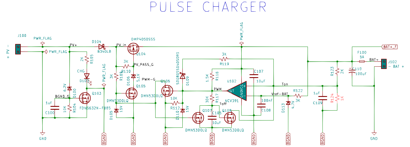
The pulse charger is engaged via the bias control circuit when the PV voltage sufficiently biases Q103. The threshold is set by the combination of D100 and R104, and C100/R104 form a low pass filter to reduce oscillation that may occur in marginal lighting or shading conditions. LED D103 indicates when the pulse charger is active.
Q103 engages the pulse charger when biased by connecting the pulse charging control circuitry to ground. This is done to prevent the control circuit's bias current from discharging the battery at night or when stored. Similarly, D104 prevents battery discharge thru the bias control circuit.
The core of the pulse charger is PFET pass transistor Q104. When voltage is first applied to its source, pull-up R110 keeps the transistor off. R109 charges the gate of Q105 which biases the gate of Q104 on. R109 also turns on Q107 which ensures that C107 is discharged and Q108 is off. Zener diodes D105 & D110 protect the gates of Q105/Q107 & Q106, respectively, from excessive voltage which could occur when no battery is present (or failed, fuse opened, etc.) and the PV panel is energized.
Comparator U102 controls battery charging. Its charging threshold reference is set by zener D113, and R122/C108 form a low-pass filter to reduce noise. Voltage divider R123/R124 sense battery voltage with C109 providing noise decoupling. The time constant of this network also sets the on time (Ton) of the pulse charger.
When the sense voltage on U102 exceeds the reference voltage its output goes high and turns Q106 on. Positive feedback via D109 & R119 keep U102's sense input high to prevent oscillation. With Q106 on, Q105 & Q107 turn off. Q104 turns off, disconnecting the PV panel from the battery. With Q107 off, C105 begins to charge via R117. Their time constant sets the pulse charger off time (Toff). Q108 turns on when its gate threshold voltage is reached and pulls U102's sense input low, thereby resetting the Ton time by discharging C109.
U102's output goes low, discharging C105 and turning Q104 on again, and the process repeats. The Ton & Toff time will vary with the battery voltage but Ton much more. Practically speaking (but not entirely accurate), Toff is relatively constant and could be thought of to set the PWM frequency and Ton the duty cycle.
Pump Control
The Pump Control circuit provides Under Volt Lockout (UVLO) and Over Current Lockout (OCLO) protection for the battery. When either feature engages the control circuitry is locked out (unbiased) and must be reset by turning SW100 off. The UVLO threshold is ~ 10V and OCLO ~ 3.4A.
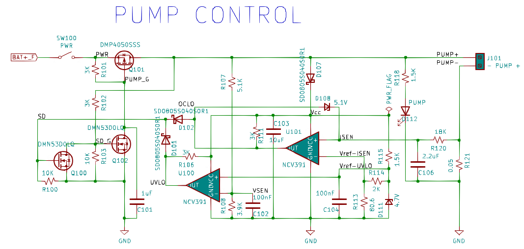
The circuit is energized when SW100 is turned on by the user. Pass transistor Q101 immediately turns on due to the initially low impedance of C101. The time constant of R101 & C101 provides the delay necessary for the control circuit to begin normal operation. Q102 turns on and pulls the gate of Q101 down hard. This positive feedback loop maintains power to the control circuit and pump. LED D112 illuminates to indicate that the circuit is operating normally.
The control circuit receives Vcc via D107 which is connected to the output of pass transistor Q101 (PUMP+). D107, in conjunction with bulk capacitance C103, ensures that Vcc is maintained long enough after a fault condition is detected to latch the circuit off. R115, D111, and C104 provide reference voltages for the under-volt & over-current lock-out features.
U100 provides under-volt protection. Battery voltage is sensed via voltage divider R107/R108 and compared to the reference voltage. C102 provides noise decoupling and a small time delay to ignore transients caused by high pump starting currents. When the sensed voltage falls below the reference the output of U100 goes high and turns on Q100. Q102 turns off, C101 begins to charge, and Q101 turns off. D101 & D102 OR the outputs of both features to control Q100.
U101 provides over-current protection. The analog of pump motor current is provided by R121. R120 & C106 form a low-pass filter and time delay (~167mS) to ignore starting currents & transients. R114 & R113 set the current limit. When the threshold is exceeded the output of U101 goes high, and positive feedback via D108 prevents oscillation. D102 is forward biased and circuit shutdown proceeds as described above.
Discussions
Become a Hackaday.io Member
Create an account to leave a comment. Already have an account? Log In.