 Alex Brown
After months of procrastination and brain-fog, back in August I designed a PCB for the SSD Drive. Finally, here it is.
This is the PsiDrive.

At the moment it can only dump SSDs. But hardware-wise it's almost identical to the breadboard with the Pico, just with some better decoupling. That experimental TinyUSB firmware in my last log should do the job.
I'll cover the PsiDrive in more depth in the future. For now, I want to cover its spiritual parent: the Psion Siena SSD Drive.

As its name indicates, this was designed to be used with the Psion Siena. Unlike every other SIBO machine, the Siena didn't have a built-in SSD Drive, so this was a separate device that you could buy. It plugs in to a port on the top of the Siena - the 15-pin PCMCIA-style connector known by Psion as the Honda connector. Interestingly (although undocumented), the drive worked with the Series 3c and 3mx, but not later devices. I'll go into why this is later.
My aim with the PsiDrive is to make something the same size as the Siena drive, so I want the PCB to be the same size. So it stands to reason that I need to take this thing apart to see how they've squeezed things in.
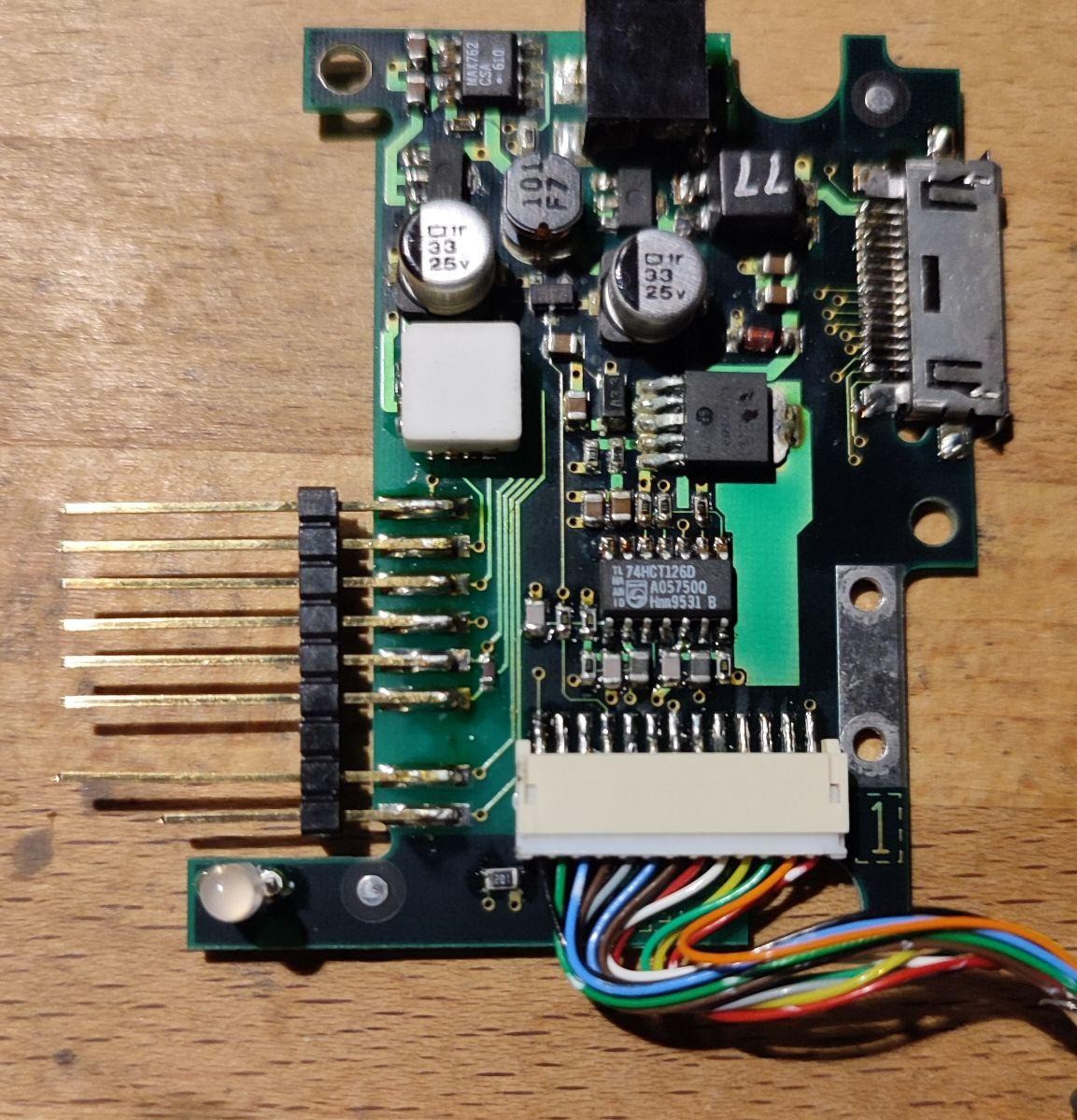
At the top of the board is a 6V negative-pin barrel jack for power. This can be used by the Siena as an external power source. It's ignored by the 3c and 3mx.
The 6 long pins on the left go into the SSD. The bottom two are part of the SSD detection circuitry. The 13-pin connector goes to the Honda cable, and the socket on the right is a pass-through Honda connector for RS232.
I have no schematics and I haven't scoped it yet, so the rest of this is pure guesswork.
Taking a guess...

I have no idea what the white box is - maybe an optocoupler?
At the top and on the right is probably a boost converter for the ~17V Vpp for Flash SSDs. This can be 16V-19V and is unregulated on a SIBO machine; Flash SSDs have an LM317LM on-board for the flash chips to knock this down to 5V or 12V, depending on the board.
I think there's a 5V regulator at the top, as the Siena doesn't supply any power over the Honda cable.
The thing I hadn't noticed before is the 74HCT126D.
"Undocumented" Honda
Psion PDAs from about 1995 onward — basically the Siena and 3c through to the Series 7 and netBook — use the Honda connector.
For a while the only documentation I had for the Honda port was from the Series 5 service manual. This picture, showing the pins.
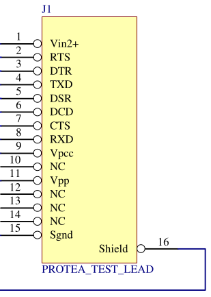
As you can see, pins 2-8 are used for RS232, plus a few for power in/out and GND. I assumed that this was the way every Honda connector was wired, so the Siena drive either had to work over RS232, or there was some weird detection process that switched the RS232 pins to "SIBO-mode".
So, when I got hold of a Siena drive, I decided to tear it down. You might be able to see from the pictures above that I was wrong in my assumptions. I realised that, on the Honda SIBO machines, pins 9-14 were a "hidden" SIBO-SP port. I'd assumed it was undocumented, because it wasn't in any of the SDK files I had at the time, so I put the drive away and decided to come back to it later.
Then, two months ago, I was sent an extra file. An update to the SDK I didn't have - 2.15 Beta.
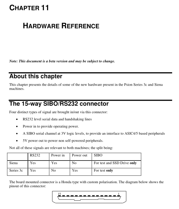
This is a new chapter for Vol 2, Book 5 of the Psion SIBO C SDK - the Hardware Reference.
The top-half of the page is the pinout for the Honda connector. The interesting part (for me) is in the following page.
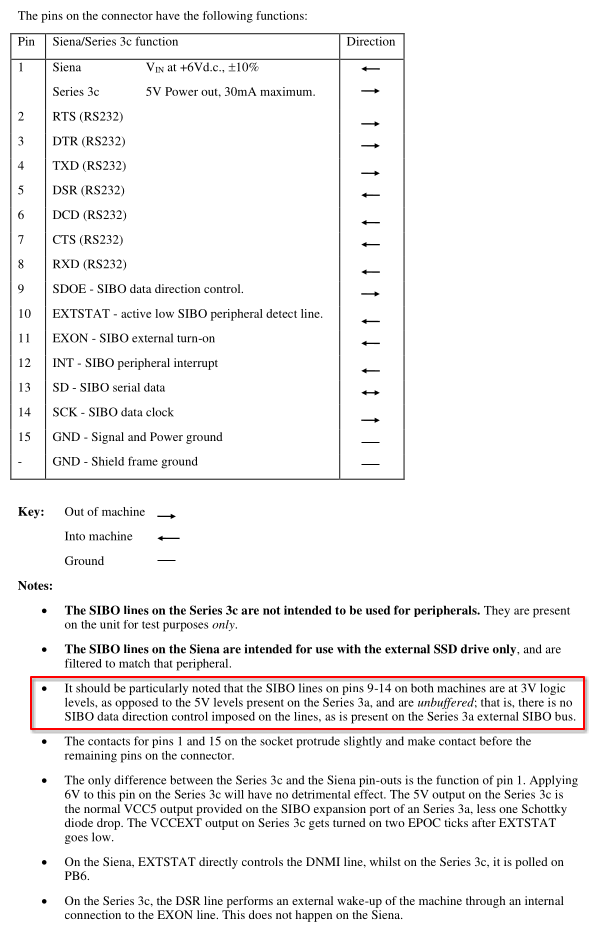
It should be particularly noted that the SIBO lines on pins 9-14 on both machines are at 3V logic levels, as opposed to the 5V levels present on the Series 3a, and are unbuffered; that is, there is no SIBO data direction control imposed on the lines, as is present on the Series 3a external SIBO bus.
All Psion SSDs use 5V logic - some are TTL (ASIC4), some are CMOS (ASIC5), but they're all 5V.
Final Thoughts (For Now)
So, is this is where the 74HCT126 comes in? Is that what's converting the 3V (or 3V3?) to 5V? And if so, what's doing the bi-directional conversion back to 3V?
Here's the datasheet: https://assets.nexperia.com/documents/data-sheet/74HC_HCT126.pdf
This is important to me, because I'm using a 74AHCT1G125 and a 74AXP1T45 for level conversion from the RP2040 on the Pico. If there's a different way of doing it, I want to know.
I need to get a scope on this to properly work out what's going on, so I'll borrow one in the next couple of weeks and see what I can find.
To be honest, though, this is where I really need a schematic for the Siena drive. The odds of me finding one are practically zero. But then again, the odds of me having most of the Psion docs I have have been close to zero, so I'm going to stay optimistic. If anyone has a copy, please drop me a line.
Discussions
Become a Hackaday.io Member
Create an account to leave a comment. Already have an account? Log In.