This is one of about a dozen VistaVision motion picture cameras built in the mid 1950's for Paramount Studios by the Mitchell Camera Company.
At that time Paramount and the other Hollywood studios were competing in the “Widescreen Wars”, an attempt to fend off the encroaching new medium of television (and poach eyeballs from each other) by using large-format cameras and projectors to offer an ever more epic cinema experience.
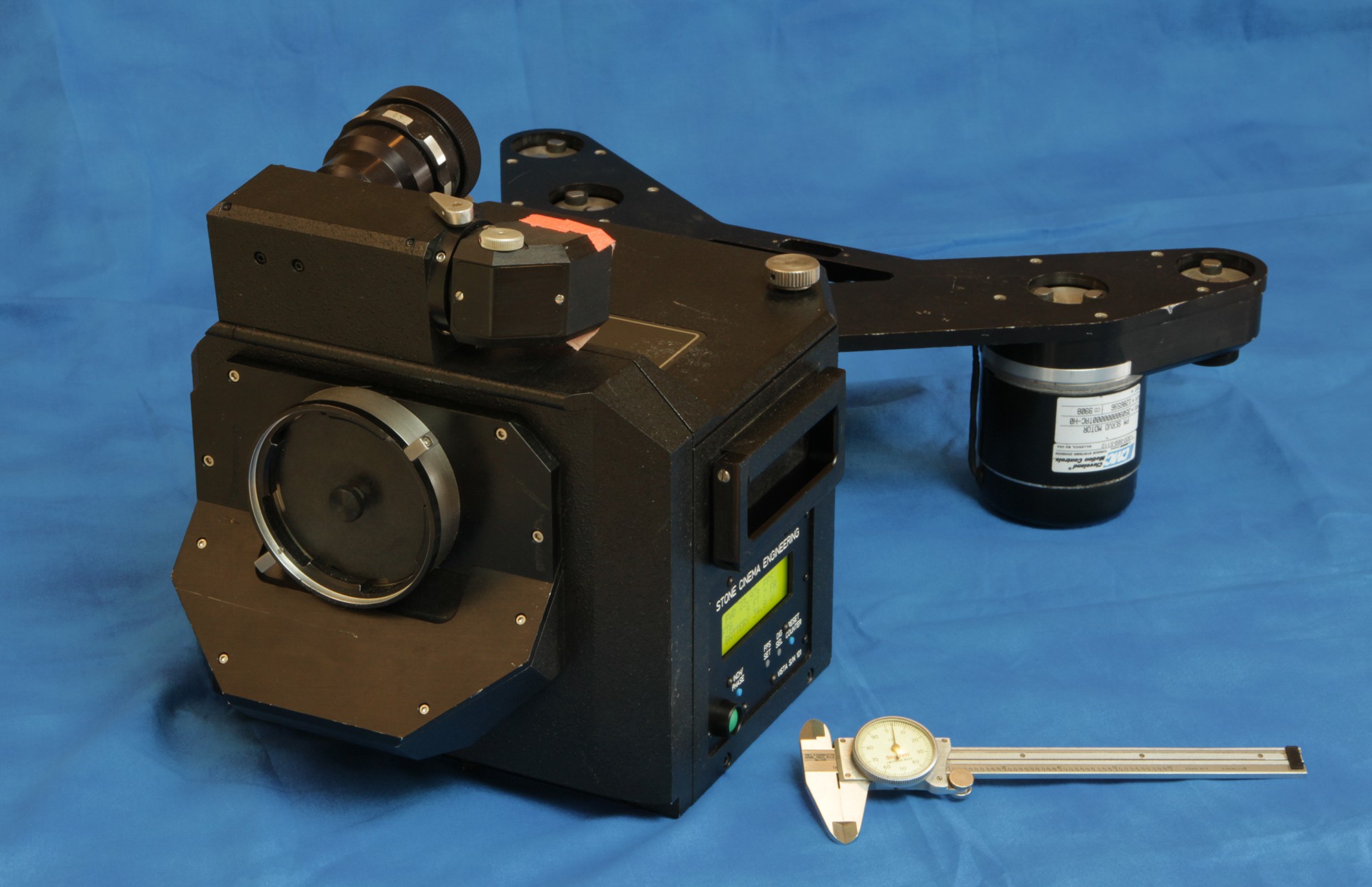
Gaze with wonder upon the beast that is one of these old cameras. Exposing a frame more than twice the size of a "regular" camera, it's more than two feet long and weighs in at 39 pounds - not including lens, film, magazine, battery or even the viewfinder. Imagine running around back in the day trying to shoot a Hollywood epic with with this bad boy.
Here's some technical info on the format:
http://www.widescreenmuseum.com/widescreen/wingvv2.htm
Although VistaVision had an advantage over the rival 65mm formats - it used normal filmstocks, lenses and processing machines - these weren't knockouts and it never got much traction outside of Paramount.
Still, there were many notable films shot in this format, Including the Ten Commandments, War and Peace, Vertigo, and North By Northwest. There's no documentation, but given the small number of Vista cameras, some of that footage was likely shot with this very machine.
https://en.wikipedia.org/wiki/List_of_VistaVision_films
But soon the advent of finer-grained film and good anamorphic lenses allowed crews to shoot widescreen films with normal 35mm cameras and the large formats faded from the scene with the last film shot in Vista in 1961.
But it wasn't dead yet.
With the surge of visual effects heavy films in the 80's, production companies found that VistaVision made a good acquisition format for VFX work. The large frames meant less grain, the spherical lenses did not have the optical distortion of anamorphic lenses and the FX unit could use the same film stocks that the main unit was using, making field logistics and color-matching easier.
Specialty optical companies such as ILM, Beaumont Camera, and Fries Engineering dug the old VistaVision cameras from deep in the back of storage rooms all over Hollywood and rebuilt them with 'modern' features, like reflex viewing.
This is one of those Fries conversions from the 80's. It started life as one of the lightweight “butterfly” models, a 'small' handheld version for action and inserts, coming in at a svelte 17lbs - without film.
Fries rehoused the film movement into a studio-style body and added a spinning mirror for reflex viewing (the original had a rangefinder). It worked on many visual effects films in the 90's
But one day it sputtered and coughed out the magic smoke and it would run no more. It sat on a shelf for several years till the owner asked me if I could get it running again.
When I got the camera it was electrically dead.
The original 1950's mechanism had weathered the 65 years since it rolled off the line just fine - these things were built like battle tanks - but the electronics were a different story.
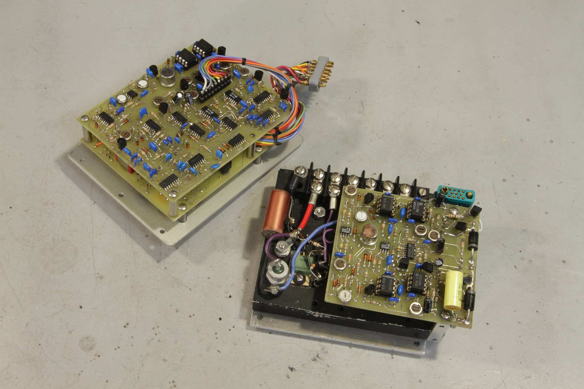
They date from the early 80's rebuild and were mostly analog, with functions spread out over many boards with a many individual adjustment pots (not a dig, that's just the way you did PLL's back in they day). It looks like the electronics went through a few generations of mods over the years - the camera serial number is RV101, so it may have been a Fries prototype. Also, this camera may have played a part in testing electronics for the IMAX cameras Fries developed about that time - they share a lot of features. But regardless, Fries closed up shop about 15 years ago, and there is absolutely no information available.
After about 30 minutes of tracing my way through the original circuits I realized that 1) something bad had happened in here, and 2) simply rebuilding it from the bottom up was the way forward.
I designed two new electronic modules for the camera.
Oddly, the new boards kind of look older than the old boards, because they use through-hole chips so that anything programmed or exposed to an external interface could be socketed for easy replacement.
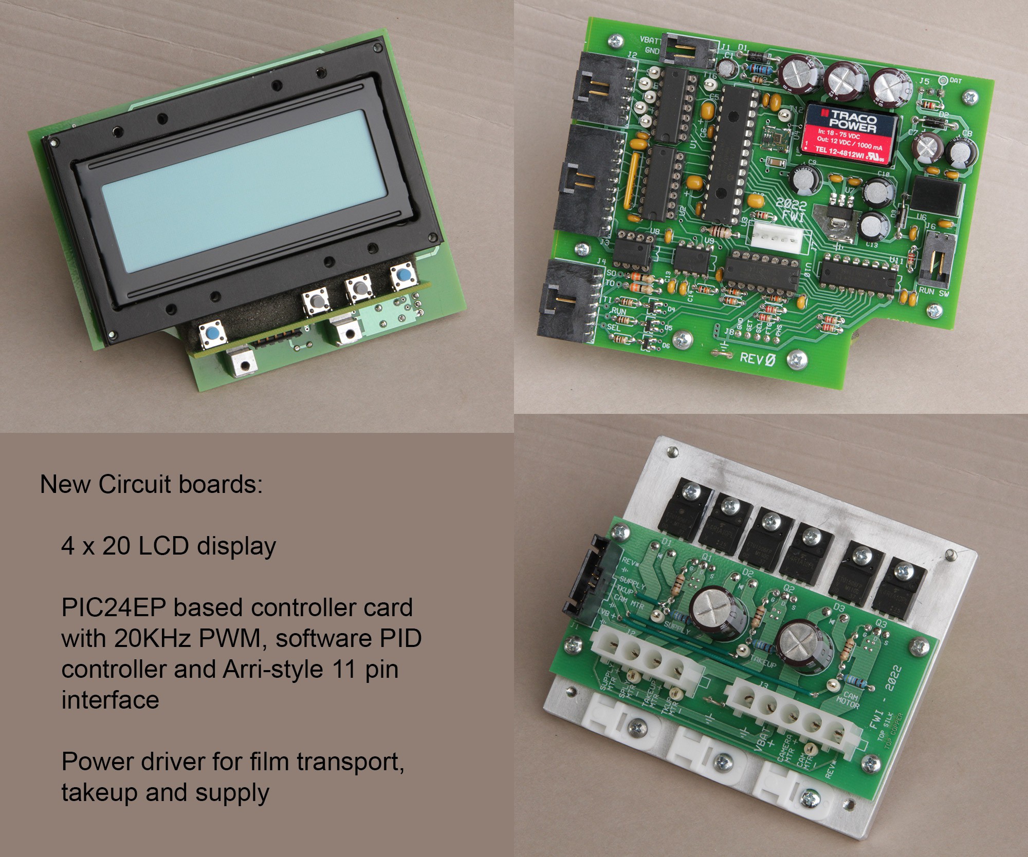
The first module was the main control board, this included the user interface, external interface, and an LCD display.
I didn't want to mechanically modify the underlying camera, so it was a bit of a squeeze to get a standard 4x20 LCD display in there. The hole in the side of the camera is just big enough for the display bezel to fit from the back, but not slip through from the outside, so the LCD and panel couldn't be built in one piece to insert from outside.
I ended up machining a complicated metal frame that held the LCD and board on one side and supported the PCB's, slipped in from the inside and attached to the front panel mounted from the other side, the panel in turn secured everything to the camera body.
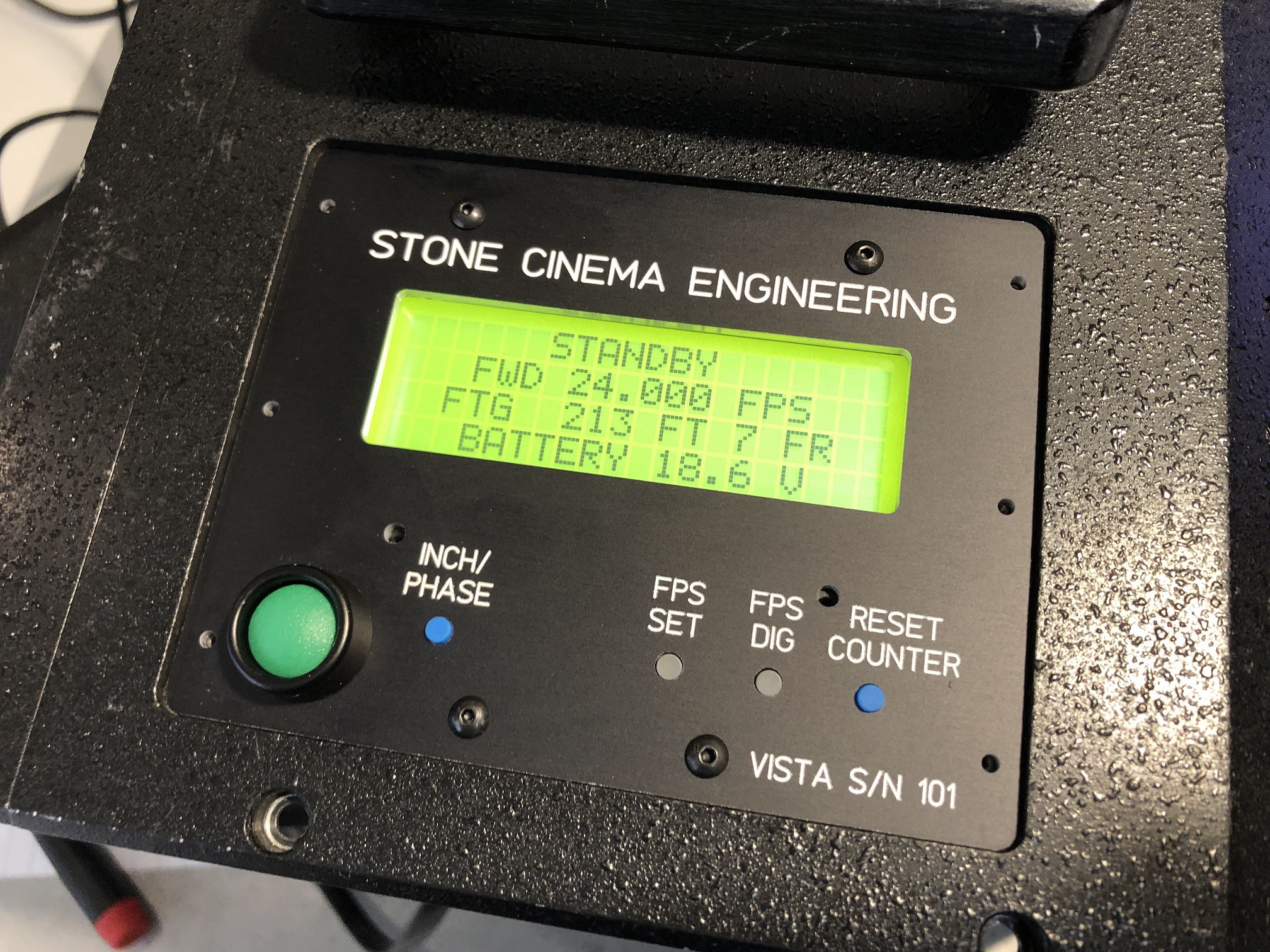
Truth be told, I would have liked to use a better display. This old-school yellow/green LCD kinda screams “1990's vending machine” to me, but with supply chains being what they are, and this being a one-off, it didn't make sense spending the the time to do anything more complicated, especially since the professional user base only cares about the data, not the look.
I had to be careful with that with big hole in the side and a self-illuminated display to make sure no light leaked inside the camera. I made custom gaskets and sealed the assembly holes and vias in the display PCB with black RTV
The electronics are otherwise straightforward. At the center is a PIC24EP family chip at 70MHz that coordinates everything. This chip has a built-in quadrature encoder interface and three PWM generators, so it makes motor control easy - once you decode the truly byzantine Microchip datasheet for these modules.
There are 3 motor drivers, one each for the camera motor, takeup hub and supply hub (for backwinding). The motor drives are all unidirectional (the camera motor has a hardware reverse switch) so the 3 drivers are all 1-quadrant, simply a big MOSFET driving the low leg. The switching frequency is 20KHz to make it inaudible, which I soon realized was pointless since the camera sounds like a washing machine when it runs - it was obviously not designed for sync-sound work.
The speed is variable from 1.000 to 36.000 FPS in .001 FPS intervals. The control system is a standard PID loop updated at 1KHz. Between the fact that a camera motor is commanded to run a constant speed, and the large rotating mass involved, the derivative term turned out to be basically useless, so after a little testing I just dropped it.
The final user controls closely follow the pattern of those on the Arriflex 435 - kind of the “standard” modern motion picture camera, and one that any professional operator should be familiar with.
One interesting thing is that the camera originally contained a brake to help when stopping, but I had to remove it to find room for a modern shaft encoder. Without the brake this camera takes a while to stop, wasting about three or four of feet of film. I found that if I added some drag by using the supply side motor (which is usually unpowered when you go forward) I could do a controlled stop, plus end up with a nice snug film pack as a bonus.
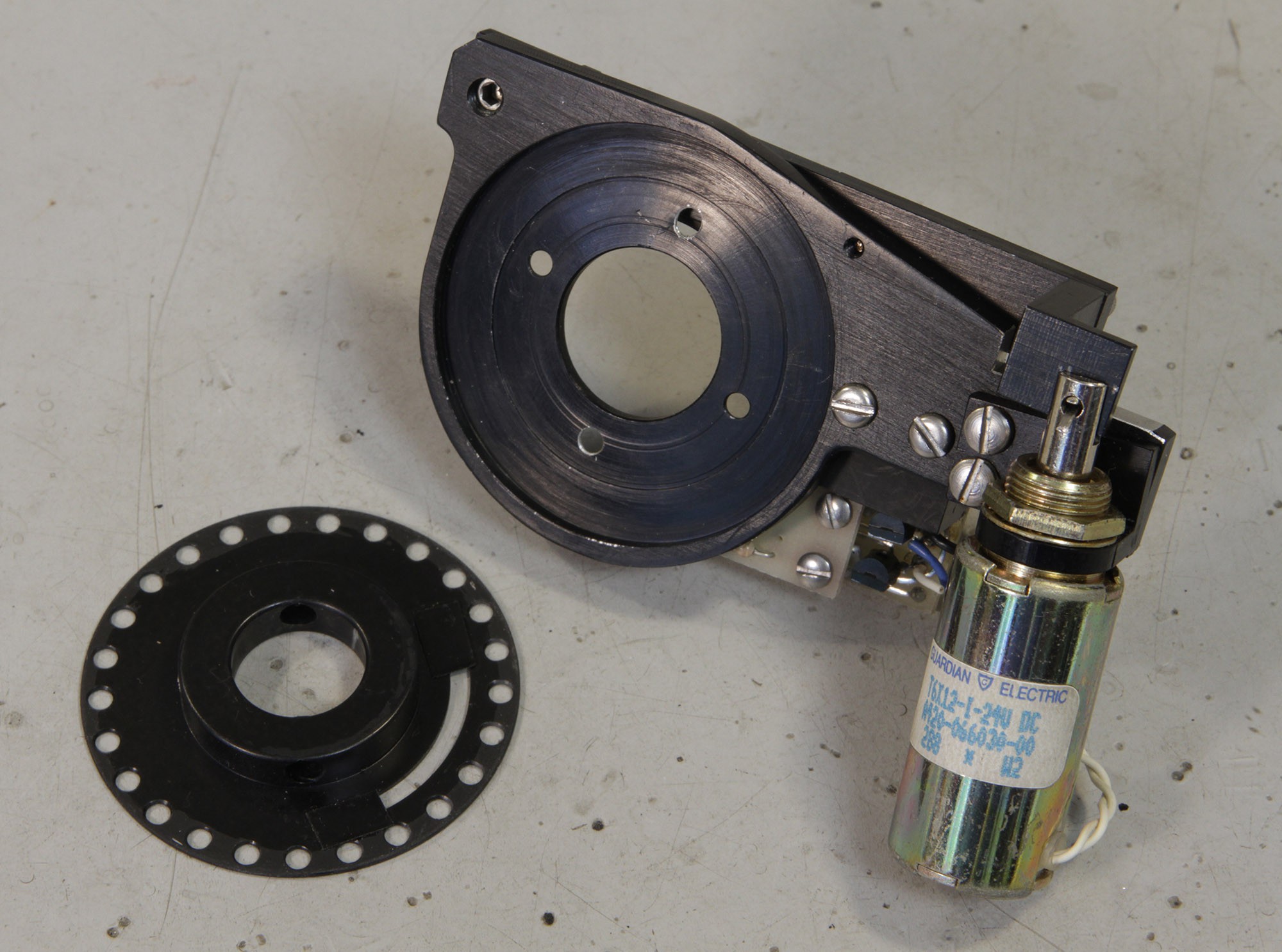
This is the brake and the original encoder. It was a good brake, a noble brake even, but it just had to go, there was just no room because the old 25 hole motor speed sensor disk really needed an upgrade.
I replaced it with a modern 800 count quadrature encoder. Having 32 times more resolution dramatically improves speed control, but just as importantly it allows me to derive certain signals to provide an industry-standard Arri-B family interface port. This camera will be used in complicated VFX settings, so it has to interface with all the equipment that modern cameras are expected to work with.
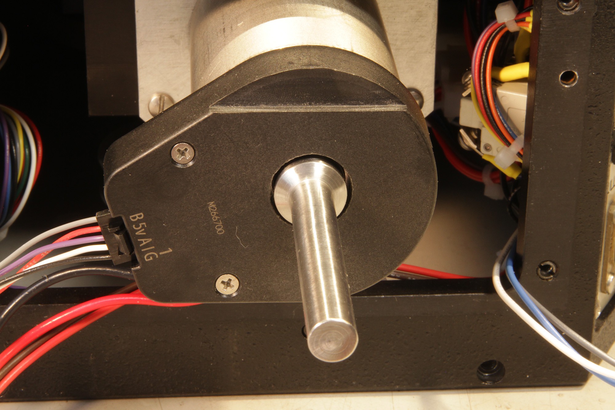
Encoder size was dictated by the large 5/8” shaft that had to go through it, meaning a 2” model, and it was a challenge to fit a thicker encoder into the camera without surgery. Fortunately, it was a modular encoder so I could take it apart and machine its enclosure a bit. I ended up facing the baseplate down to about 060”, and still had to mill a big notch into the top cover. There's about .010” of thickness left, but that's enough, it fits into the camera with a generous .020” to spare.