 John Anderson
I've had this old desktop AM radio case sitting on my shelf for a few years now. I bought it at Goodwill and I loved it's period look. When I saw it, I immediately recognized it's potential as a classic 70's "digital dice tower". So this past week, I finally got around to building the tower I envisioned when I first saw this case.
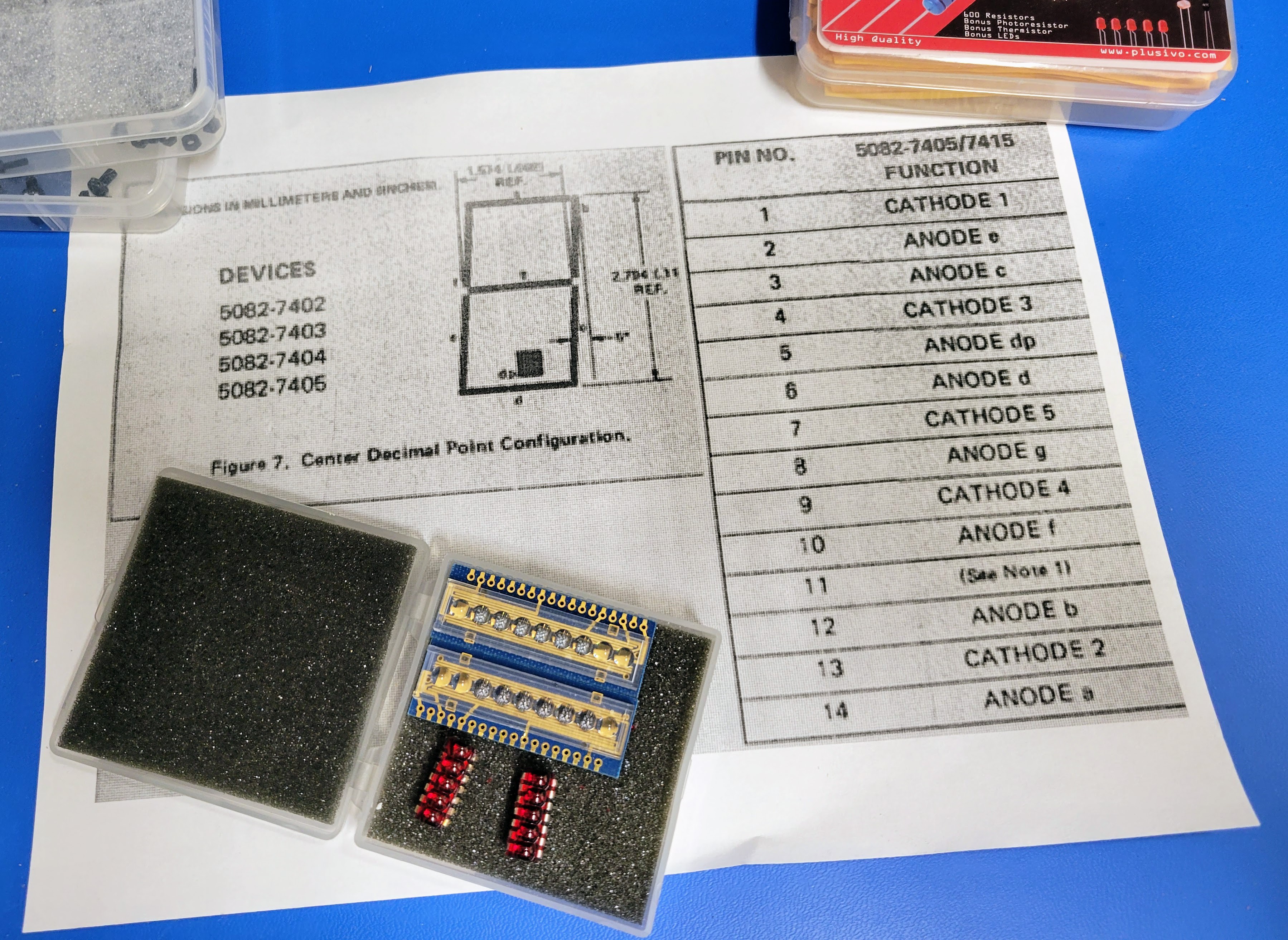
This tower uses the HP 5082-7466 HP MINI BUBBLE RED 5 DIGIT 7-SEGMENT LED DISPLAY. It's perfect for the early seventies period look. It's the same display that was used in calculators and digital watches of the era. The rest is similar to the previous Bell & Howell Digital Multimeter based build I recently documented in the blog. The only differences is a slightly more complex circuit for the LM386 amplifier and a 9 volt battery based power supply. I tried to add more filtering to reduce some of the slight buzz in the speaker. And, I had to add a 7805 voltage regulator to get the right voltage to power the microcontroller and rotary encoders.
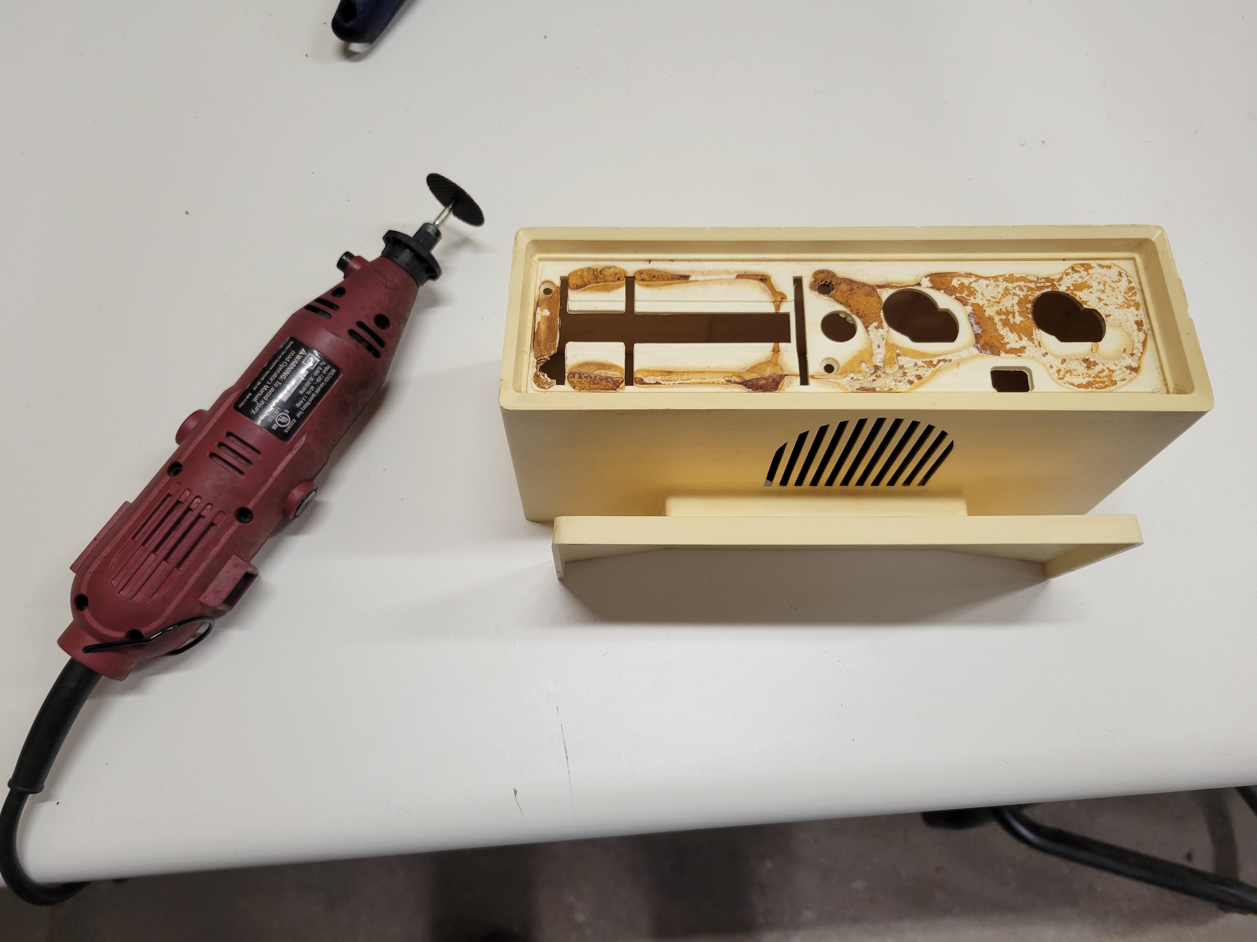
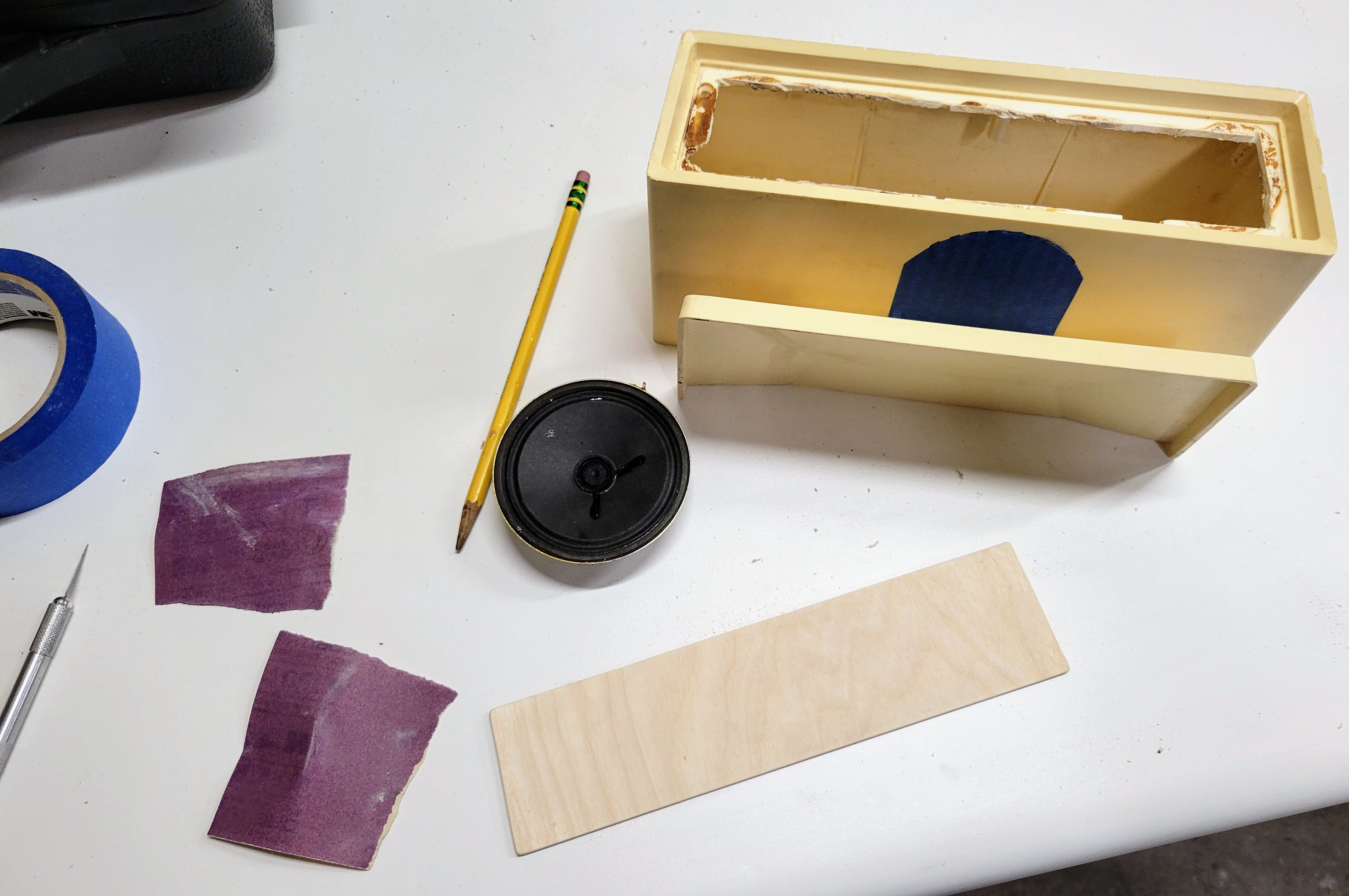
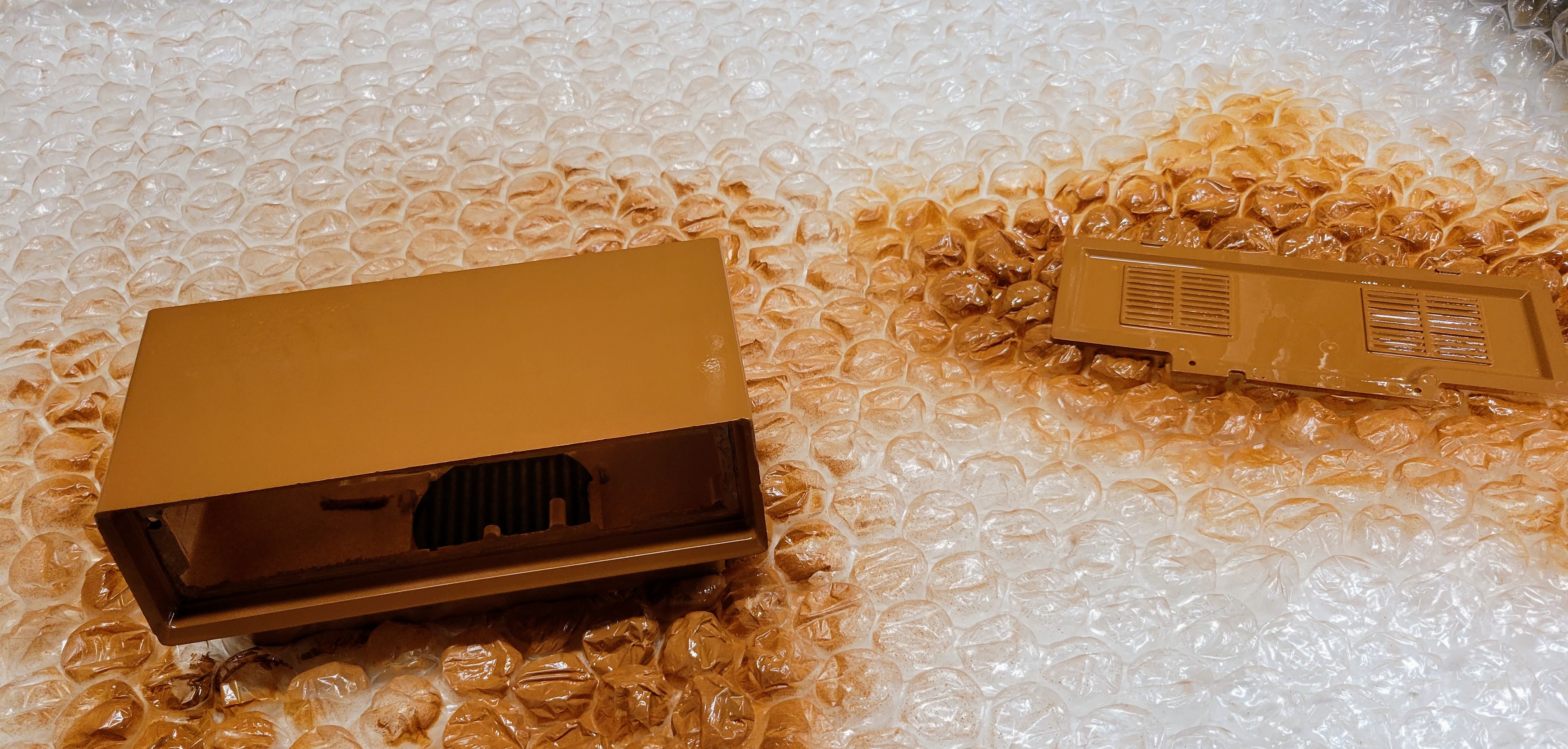
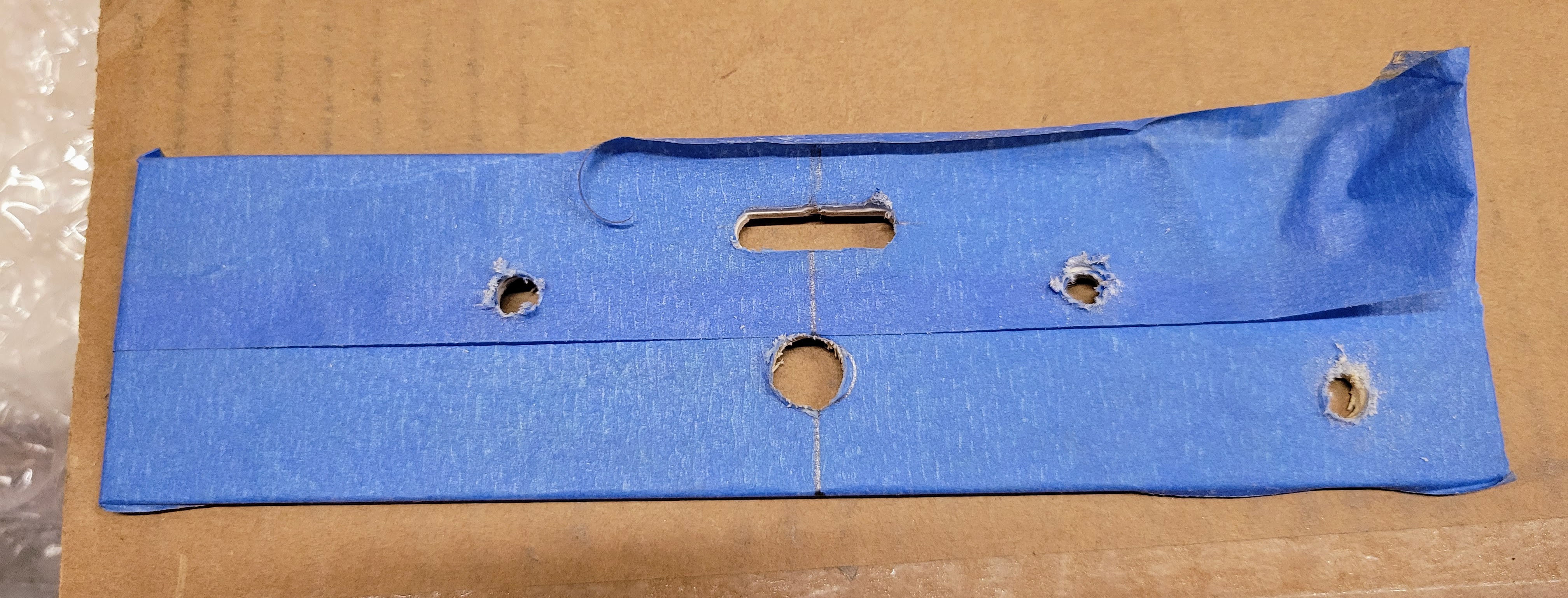
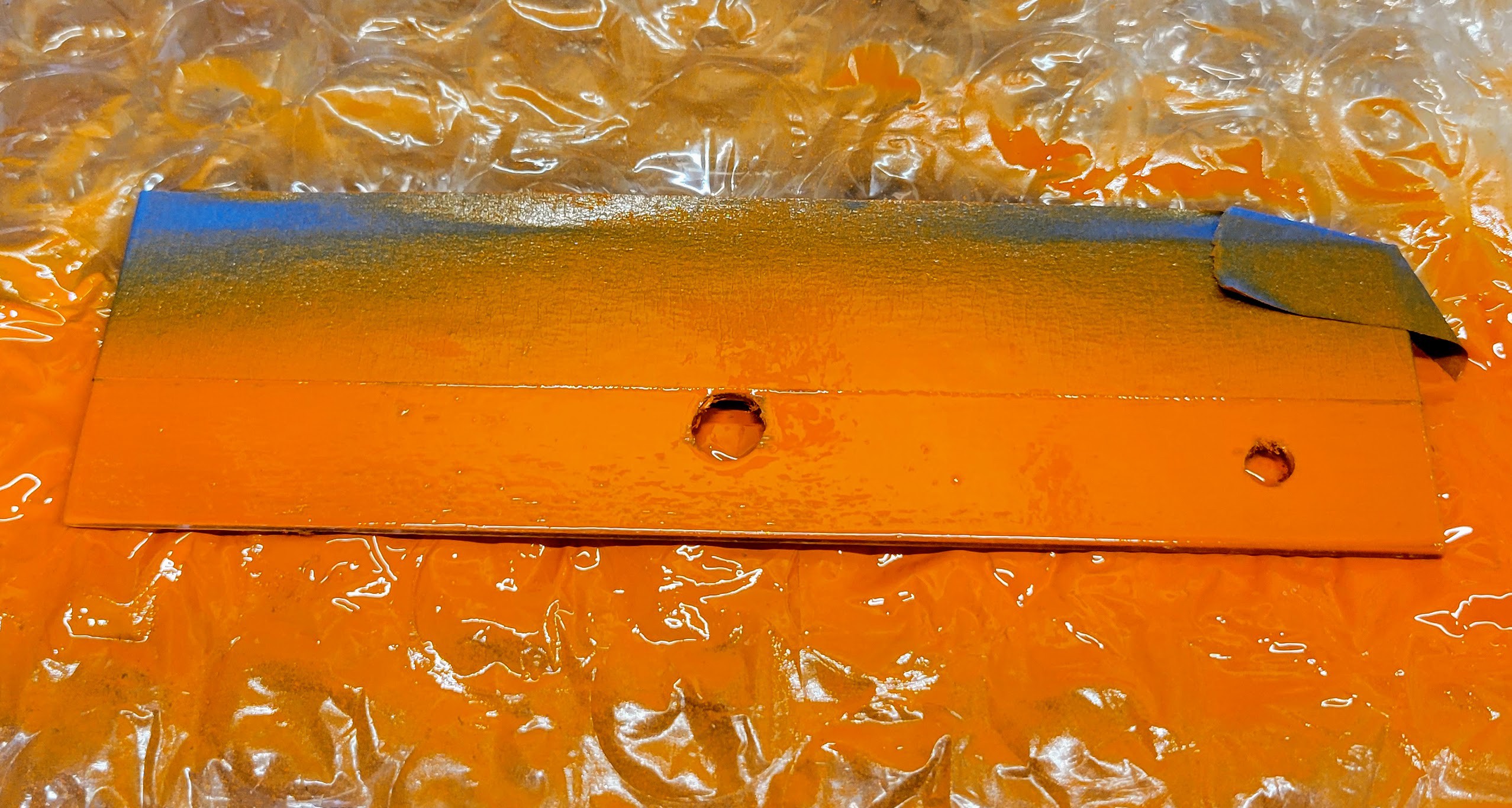
The build started with disassembling the case, painting it, and fabricating a custom faceplate from some thin finishing plywood. The faceplate was then stained and painted in a very fitting 70's color scheme.
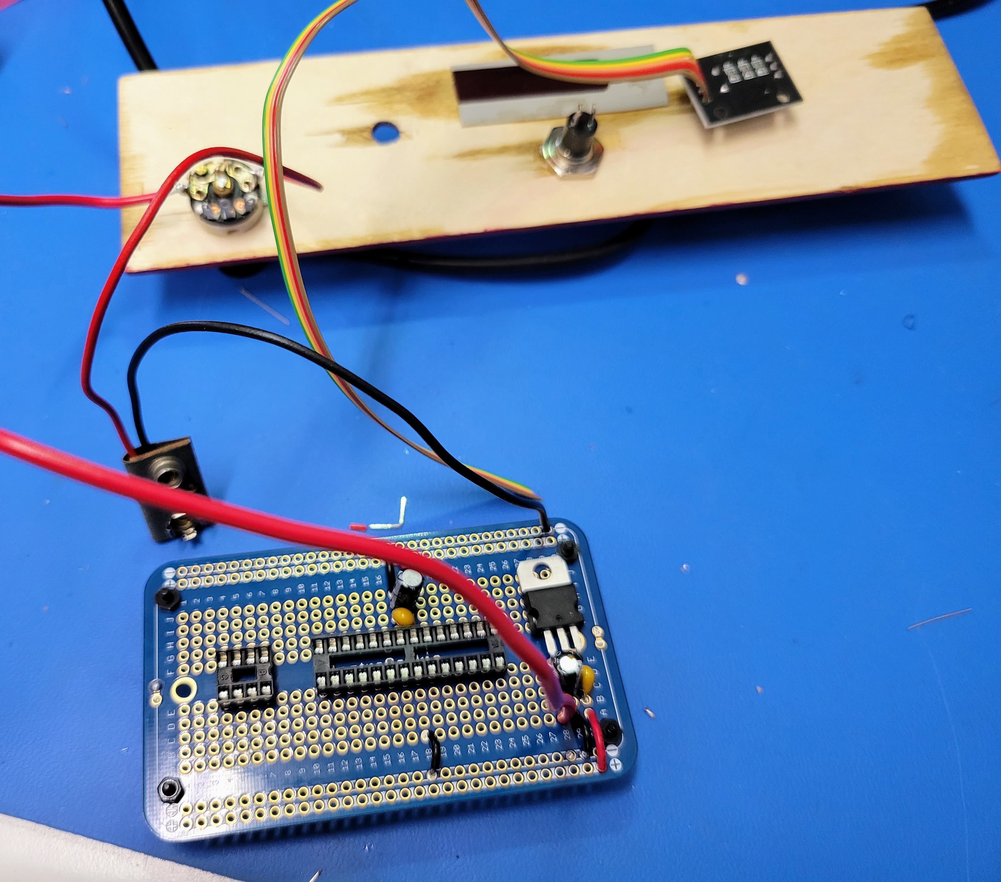
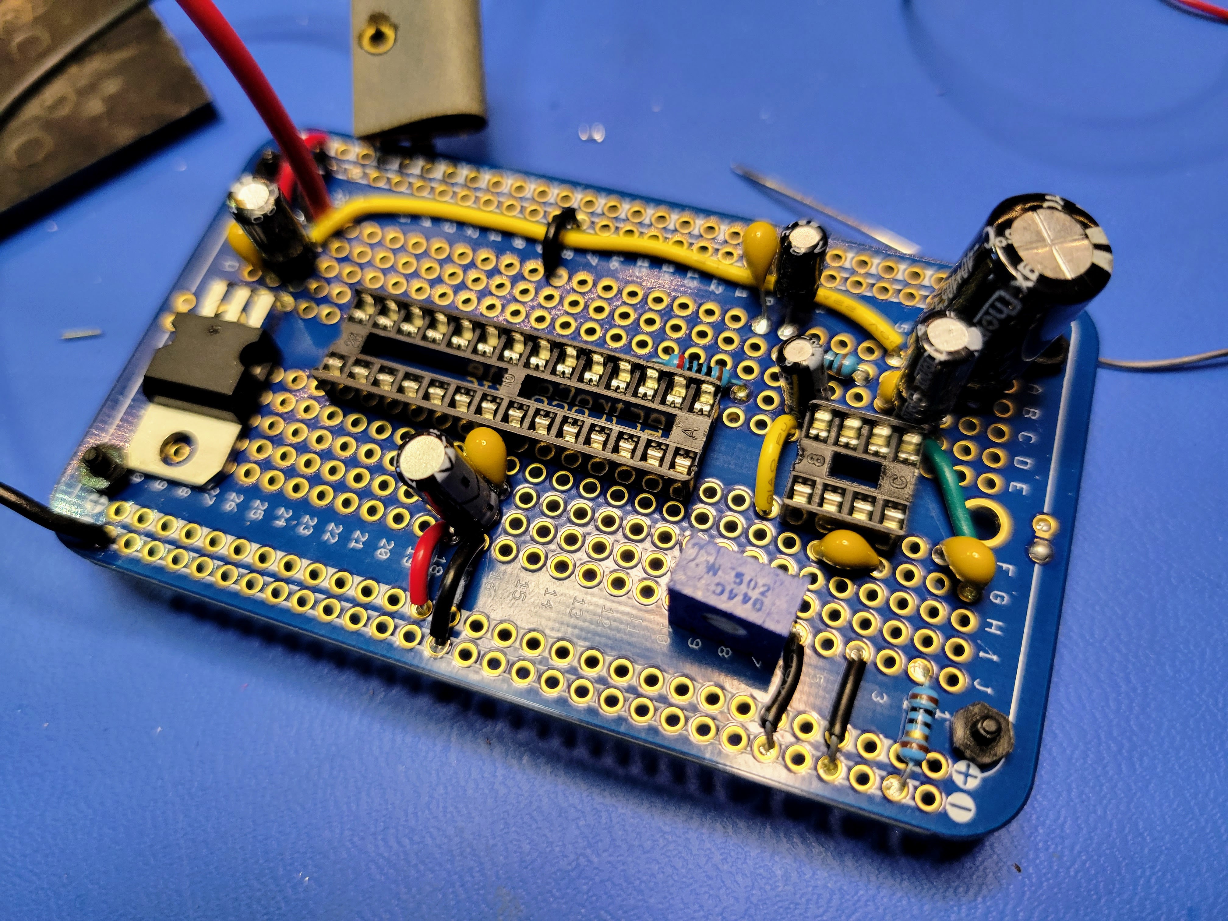
Next, I started assembling the controller board. I started with the power supply based on a 9 volt battery and a 7805 voltage regulator. I also soldered the sockets for the microcontroller and the audio amp to the protoboard. Note: The 10K pot that controls the volume also has a switch to control the 9 volt power to the controller board.
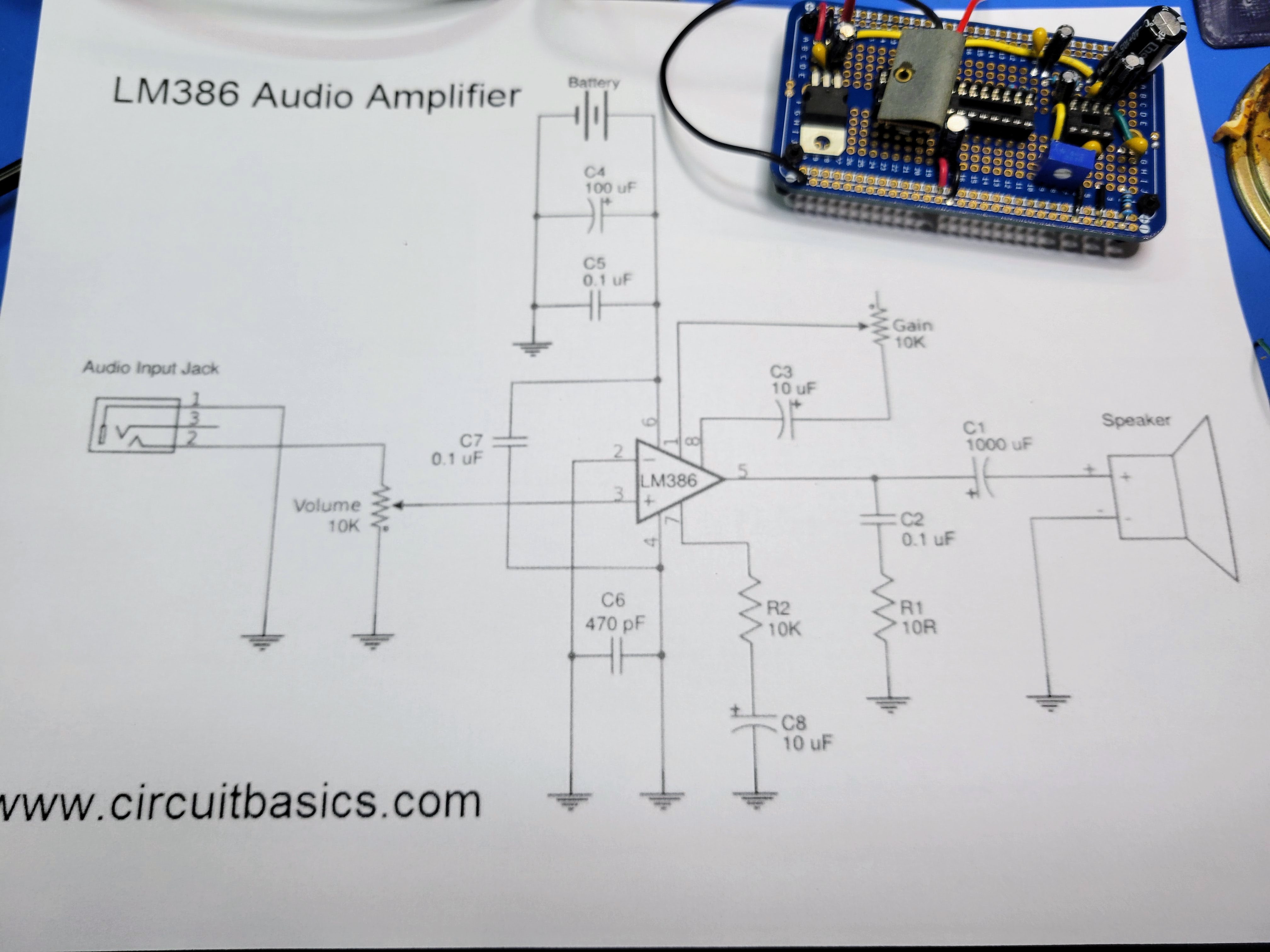
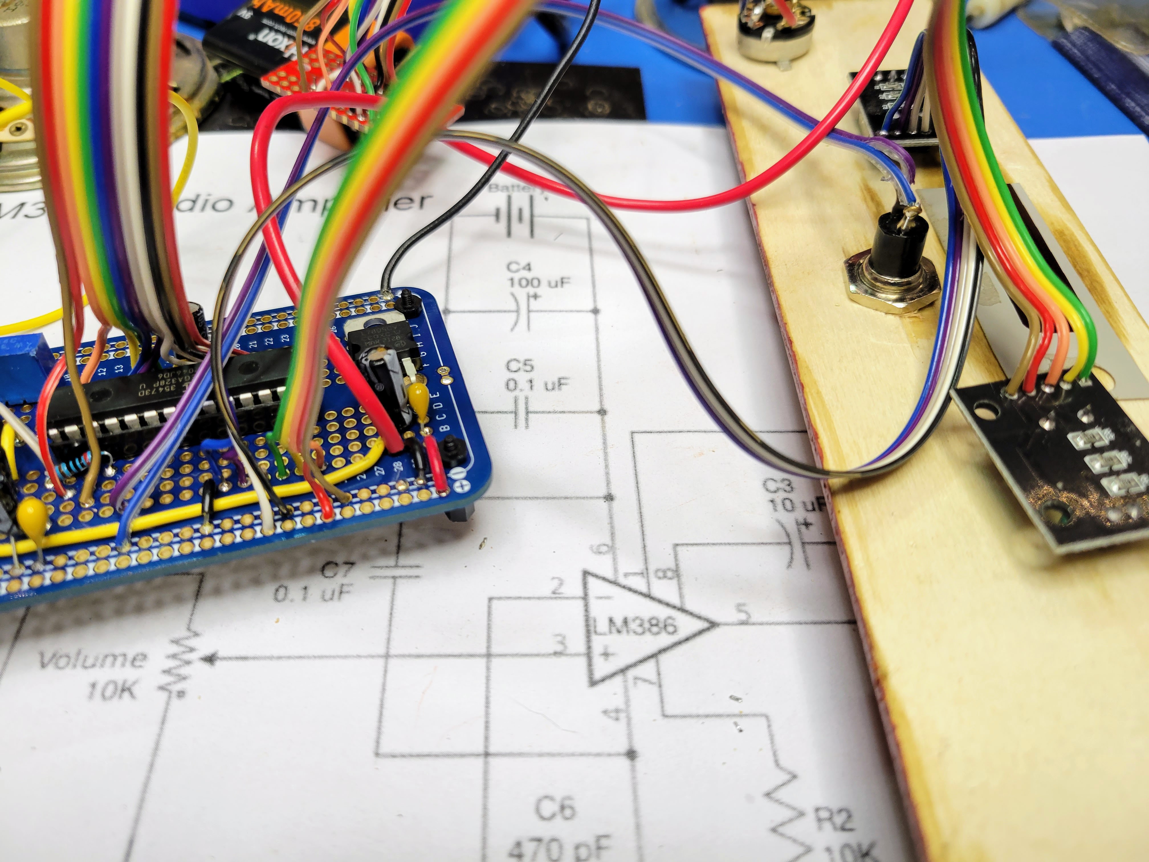
Then I wired up the audio circuit based on the LM386 audio amp. As mentioned above, this circuit was a little more involved than the one I used for the recent Bell & Howell Digital Multimeter based unit. Given the 5 digit 7 segment LED display, this board can be a little more noisy than the nixie display controller. The result was a little disappointing but worked reasonably. I added a 5K pot on the PCB to set the amplifier gain. This helped to tune it so the volume was reasonable and clipping is minimal.
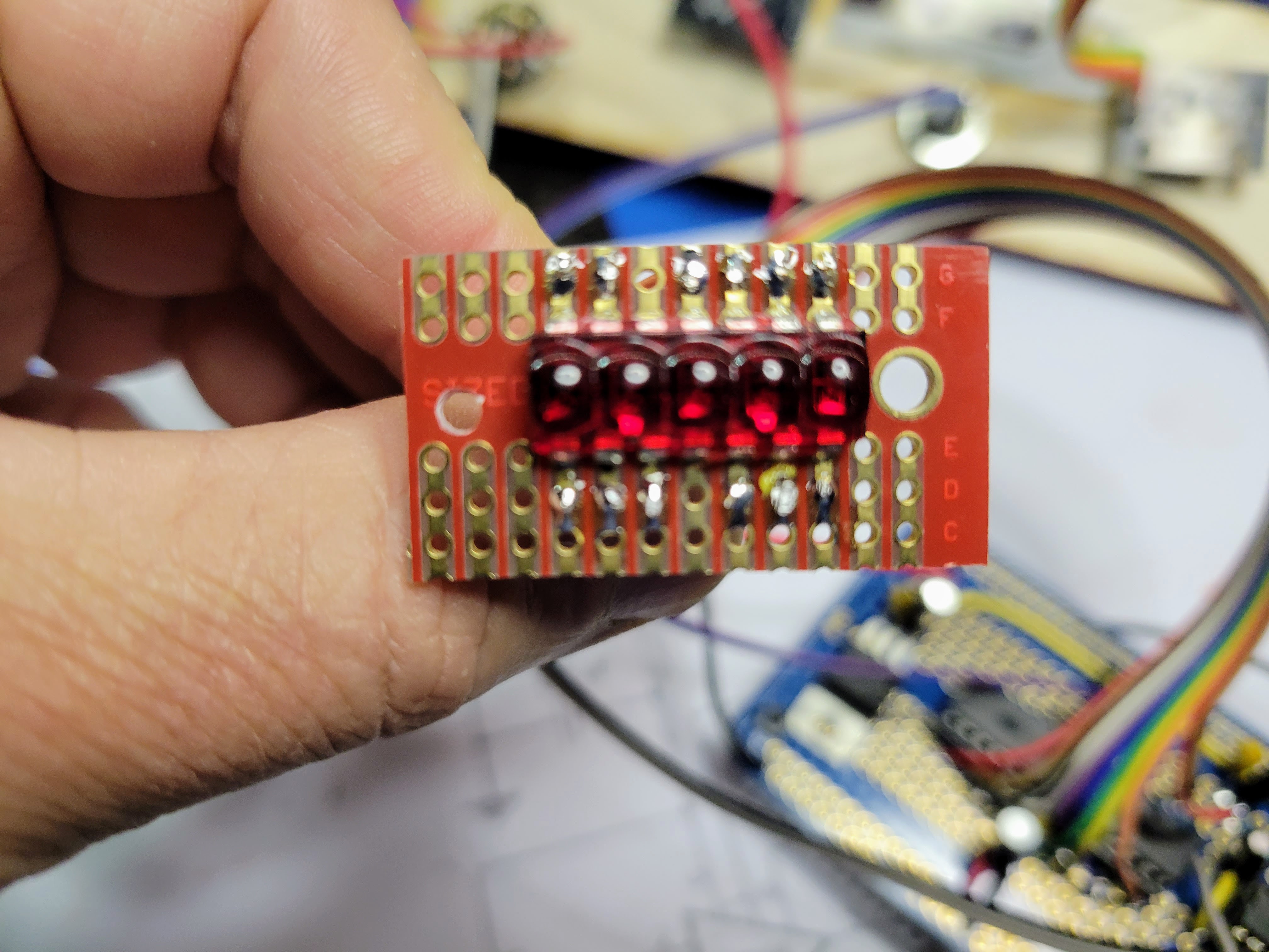
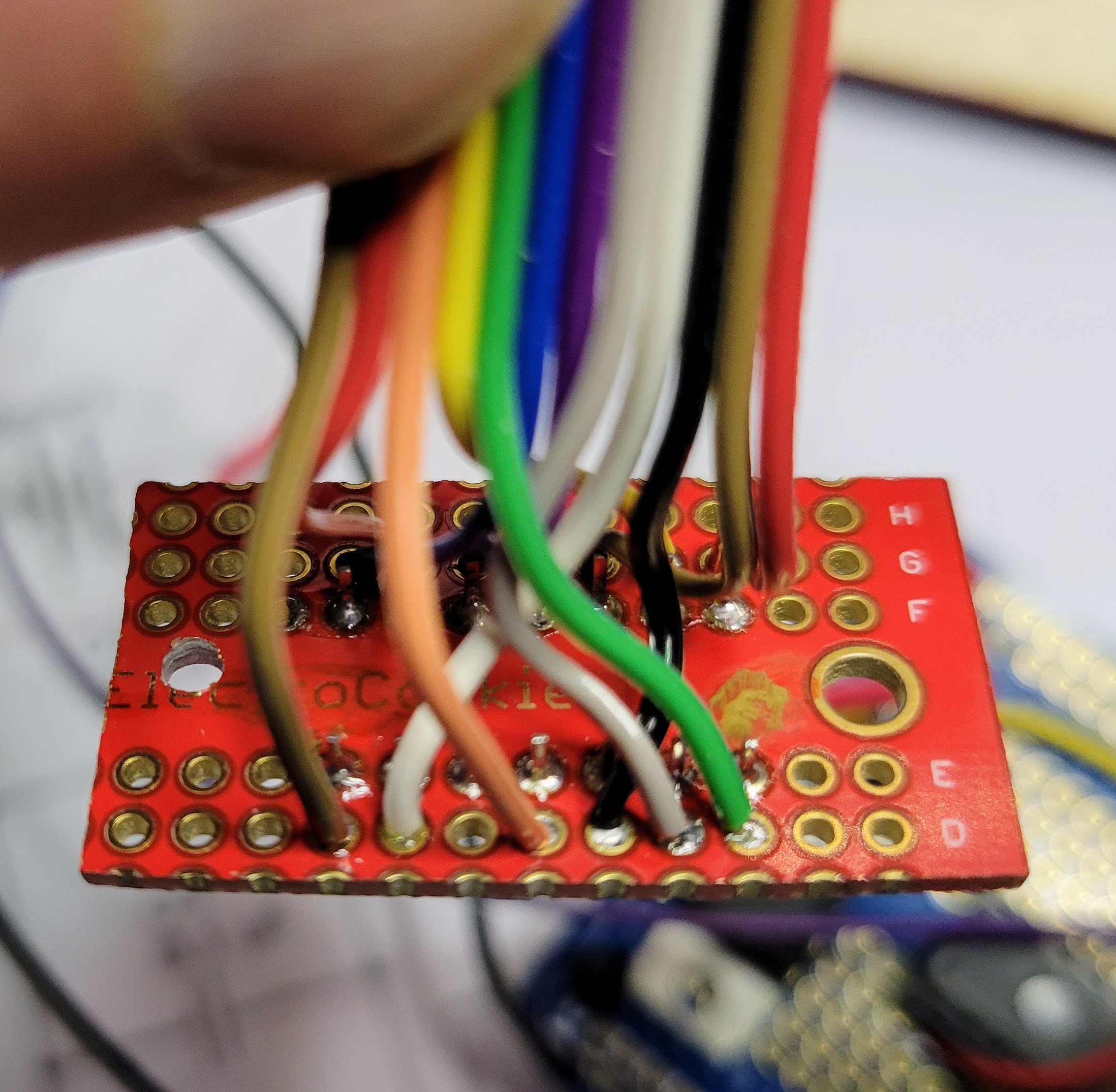
Next, I wired up the 7 segment display. I cut a small protoboard down to size to make wiring and mounting it as easy as possible. Even so, there are 12 wires from the microcontroller to the display (7 segments plus 5 digit commons). The board and wiring started to get a little busy.
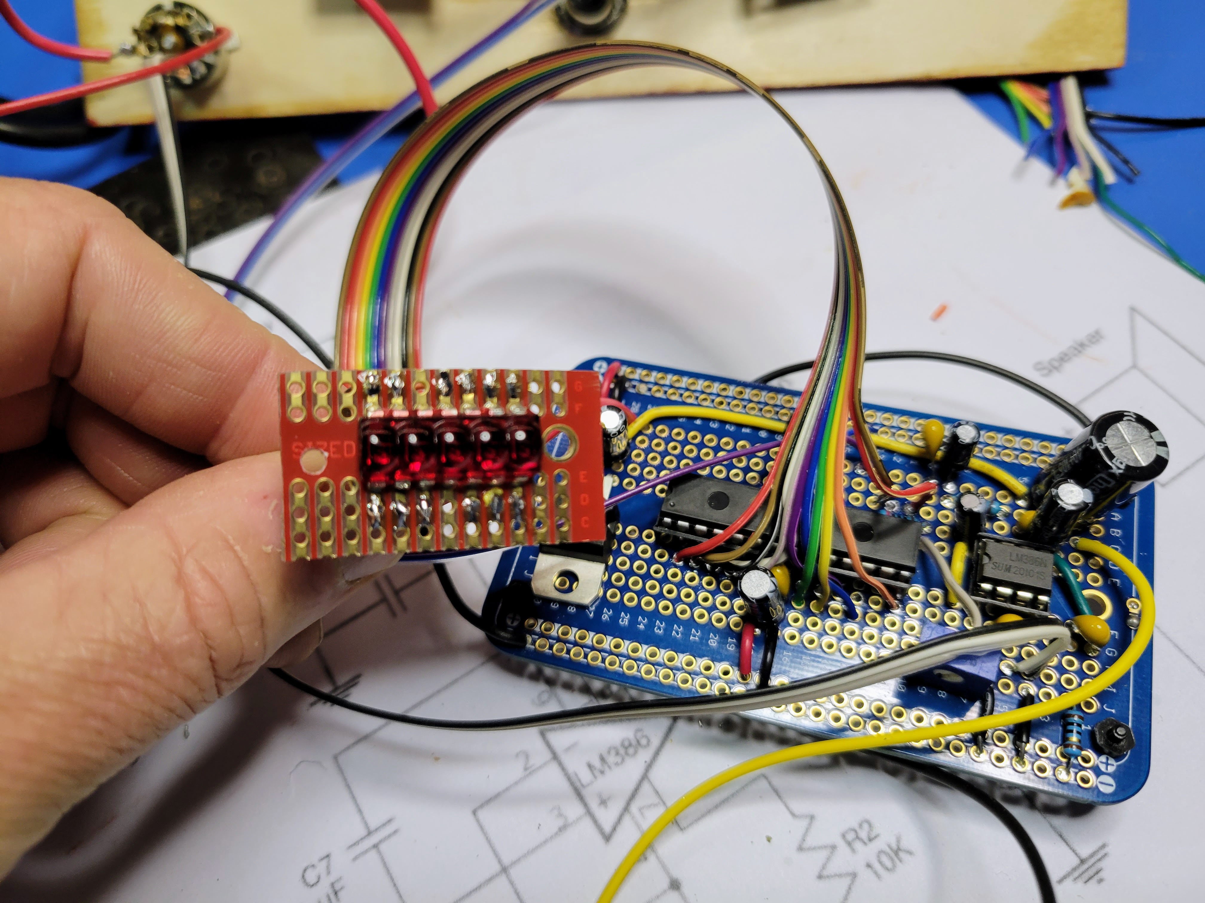
Then for the controller board, I wired up the button and the two rotary encoders.
Lastly on the controller board, I programmed the AVR microcontroller, inserted it into the 28 pin socket, and inserted the LM386 audio amp into the 8 pin socket. For the Atmel Studio project for this 5 digit seven segment LED type device, download this zip file from the project page.
Then it was a matter of mounting everything into the faceplate and assembling the case. A couple short standoffs and some hot glue held the display in place behind a red filter I cut from an old dead piece of test equipment.
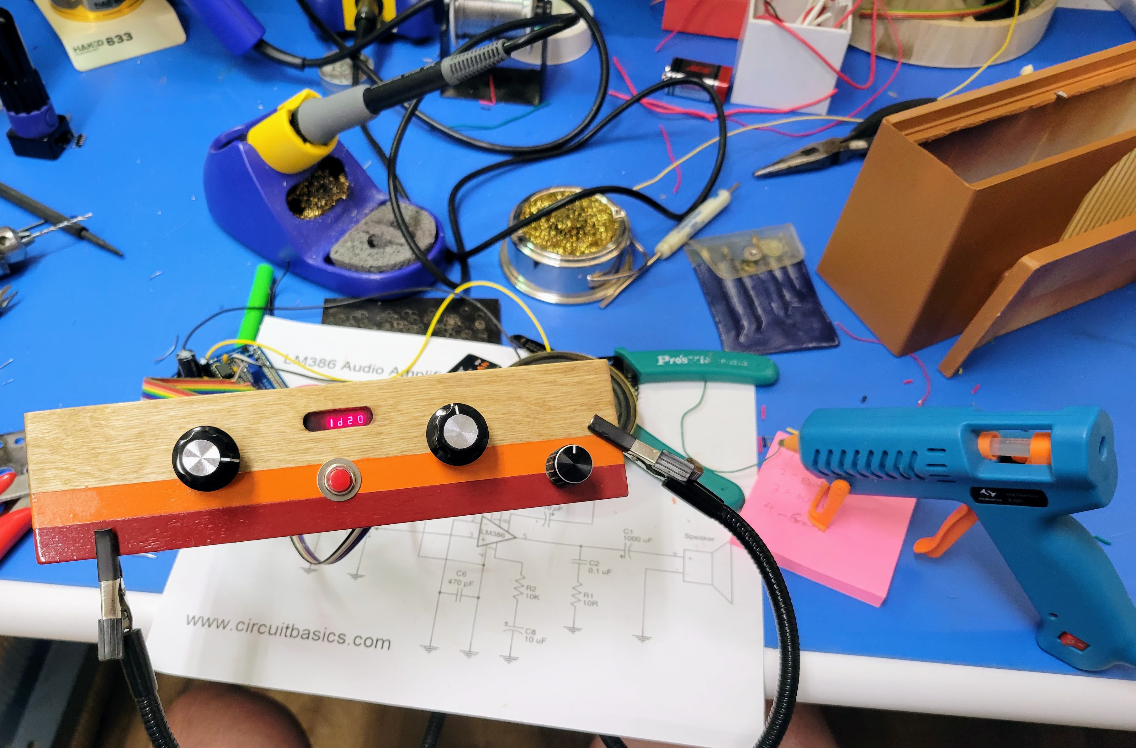
And, here's the result of my efforts.
Discussions
Become a Hackaday.io Member
Create an account to leave a comment. Already have an account? Log In.