Note: The USB-based version of this is quite a bit simpler, more reliable, and cheaper. I will be posting that soon.
For my rudder pedals, I started with PlayStation InterAct v3 pedals:
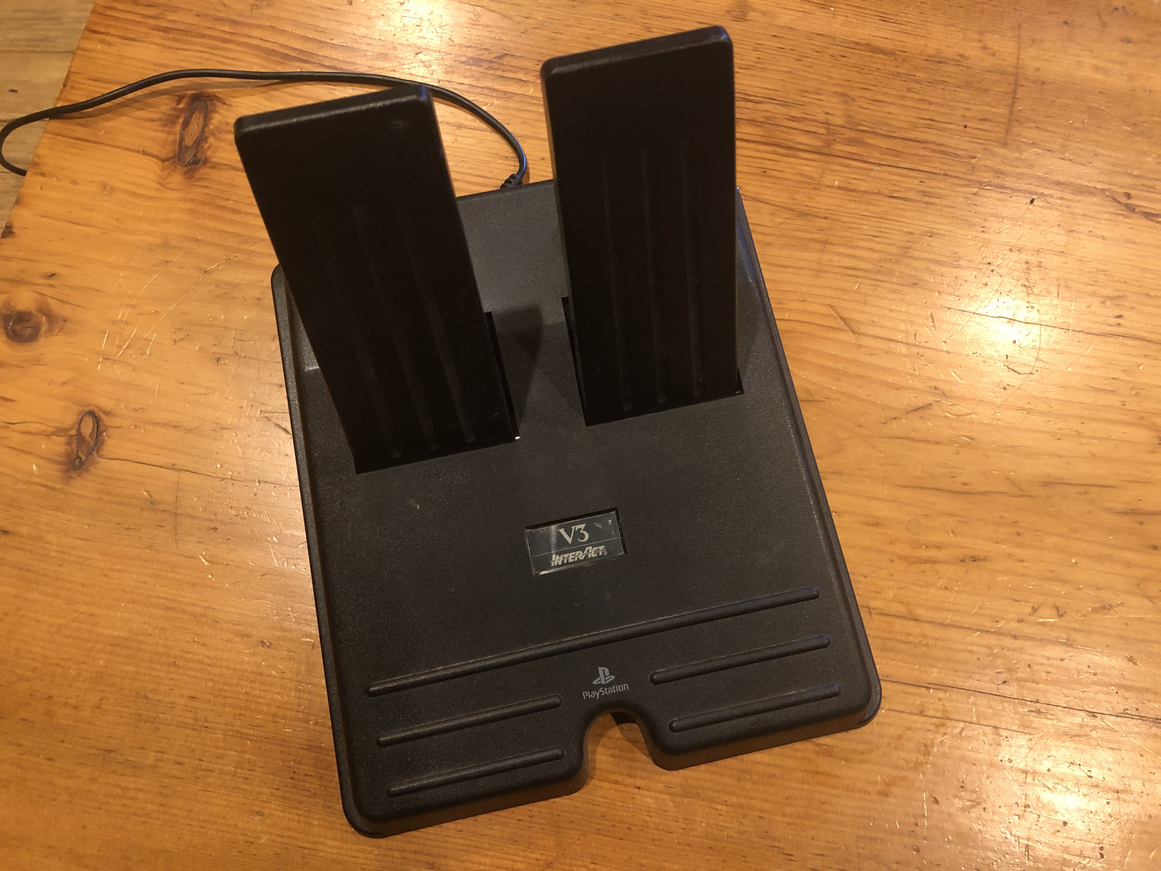
These pedals come with a wheel and are used for gas/brake in some kind of driving simulator. You can find them on eBay for ~$20 (pedals only) including shipping if you are unable to find any pedals at your local dump. The pedals are quite simple internally: They consist of two potentiometers connected to the pedal surface and there are no active components. This means that the ones on eBay listed as "untested" likely either work or are trivial to fix.
Unfortunately, I didn't have any microcontrollers with native USB support on hand, but I did have an ESP32 with Bluetooth support, so I decided to use that. I personally used an ESP32_Devkitc_V4, but any ESP32-based board should work. Note that ESP8266 boards will not work because the 8266 has only WiFi support. You may want to buy one of those ESP32 devices with a built in LiIon battery charger to give your pedals true wireless support -- I know Adafruit makes a few. I decided to use MicroPython on the ESP32 because it's quite easy to set up compared to Arduino with the ESP32 toolchain.
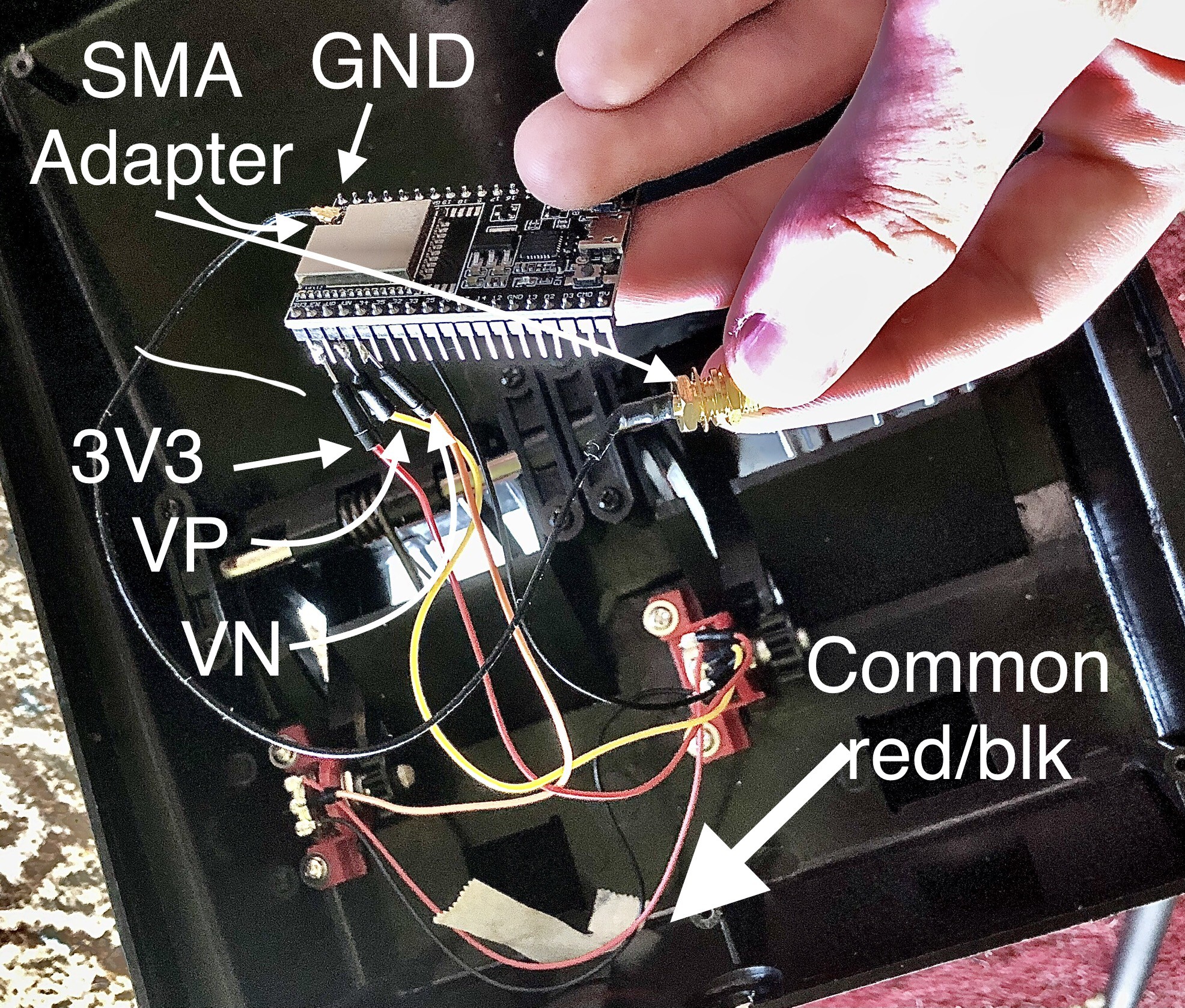
The pedals attach to the steering wheel via a Mini-DIN connector that looks something like PS/2. I wanted to save this wire for future use, so I desoldered it from the internal potentiometers without damaging it. There were two additional wires, a red and a black, connecting the top and bottom of these two potentiometers. These carried the VCC and ground, supplying both potentiometers with the same input voltage. I left these wires in place and attached these connections to the 3.3V supply and ground of my ESP32 via some spare wires (red and black). Next, I attached the center pin of the potentiometers. I attached the right pedal's potentiometer to the VP connection (yellow wire) and the left pedal to the VN connection (orange wire). Finally, I added a spare SMA adapter to the ESP32 for an antenna, both of which came from a dead WiFi router.
Now that I had the hardware setup out of the way, it was time for the software. MicroPython has a guide for setup on the ESP32, which worked first try for me. However, you may need to adjust the USB device you're using on Linux/macOS. Running `ls /dev/tty*` will give you the various TTYs on your system. The ESP32 may be attached via something like /dev/ttyUSB0 or (unlikely) /dev/ttyACM0. The numbers may vary. On Windows, you will likely have drivers to install. Second, on Linux and macOS systems, you may need to give yourself permission to access the device. On Linux, you can add yourself to the `dialout` group or `chown` the USB device to your user, which I prefer since it grants one-time access per device. On Ubuntu, you may also need to stop ModemManager with `systemctl stop ModemManager.service`. If you're having trouble connecting your ESP32 via esptool, a quick internet search can pull up a number of helpful guides that go into more depth than I can here.
Next, I used Adafruit's `ampy` tool to install software on my ESP32, which they have a comprehensive setup tutorial for. To make Bluetooth setup easy, I used the MicroPythonBLEHID (Bluetooth Low Energy Human Interface Device) library, which you can find here. The file you'll need is called `hid_services.py` -- That's the library. Once you have it on your computer (say, in your Downloads folder), you can use ampy to upload it:
~/Downloads $ ampy --port /dev/ttyUSB0 put hid_services.py
Substitute `/dev/ttyUSB0` for your ESP32's USB port. From there, I simply modified their example code to obtain my rudder pedal code
import time
from machine import Pin, ADC
from hid_services import Joystick

class Device:
    def __init__(self):
        # Define state
        self.x = 0

        self.prev_x = 0

        # Define buttons
        #self.pin_forward = Pin(23, Pin.IN)
        #self.pin_reverse = Pin(19, Pin.IN)
        self.pin_left = ADC(Pin(39, Pin.IN))
        self.pin_right = ADC(Pin(36, Pin.IN))
        self.pin_left.atten(ADC.ATTN_11DB)
        self.pin_right.atten(ADC.ATTN_11DB)

        # Create our device
        self.joystick = Joystick("Rudder Pedals")
        # Set a callback function to catch changes of device state
        self.joystick.set_state_change_callback(self.joystick_state_callback)
        # Start our device
        self.joystick.start()

    # Function that catches device status events
    def joystick_state_callback(self):
        if self.joystick.get_state() is Joystick.DEVICE_IDLE:
            return
        elif self.joystick.get_state() is Joystick.DEVICE_ADVERTISING:
            return
        elif self.joystick.get_state() is Joystick.DEVICE_CONNECTED:
            return
        else:
            return

    def advertise(self):
        self.joystick.start_advertising()

    def stop_advertise(self):
        self.joystick.stop_advertising()

    # Main loop
    def start(self):
        while True:
            # Read pin values and update variables
            self.x = self.pin_right.read() // 32 - self.pin_left.read() // 32

            # If the variables changed do something depending on the device state
            if self.x != self.prev_x:
                # Update values
                self.prev_x = self.x

                # If connected set axes and notify
                # If idle start advertising for 30s or until connected
                if self.joystick.get_state() is Joystick.DEVICE_CONNECTED:
                    self.joystick.set_axes(self.x, 0)
                    self.joystick.notify_hid_report()
                elif self.joystick.get_state() is Joystick.DEVICE_IDLE:
                    self.joystick.start_advertising()
                    i = 10
                    while i > 0 and self.joystick.get_state() is Joystick.DEVICE_ADVERTISING:
                        time.sleep(3)
                        i -= 1
                    if self.joystick.get_state() is Joystick.DEVICE_ADVERTISING:
                        self.joystick.stop_advertising()

            if self.joystick.get_state() is Joystick.DEVICE_CONNECTED:
                time.sleep_ms(20)
            else:
                time.sleep(2)

if __name__ == "__main__":
    d = Device()
    # Start in advertising mode
    d.advertise()
    d.start()
The vast majority of that code is "stolen" from their example (which means it is GPL-3.0 licensed). I changed a few important details, though. First, I put the device in advertising mode to start and changed the pin numbers. I found the appropriate pin numbers for my ESP32 in its documentation. I noticed that `S_VP` and `S_VN` were on GPIO pins 36 and 39, respectively. Second, the example math was a bit off for an ESP32. An examination of the library code revealed that it clipped values to between -127 and 127, which is the range of an 8-bit signed integer. From that and the HID descriptor in the library, I could conclude that the joystick value was transmitted as an 8-bit signed int. It is important to note here that an ESP32 has a 12-bit ADC, which reports unsigned integers from 0 to 4095. The example code worked by subtracting the left ADC value from the right, giving you a positive and negative. The problem was with the scaling:
self.pin_right.value() * 127 - self.pin_left.value() * 127
Notice here that the value is multiplied by 127, which ended up clipping the value, so the rudder was either full on or full off -- Not a fun way to fly! I knew that the ADC range was 4096, but I needed to give it a range of 128. That's (2^12/2^7), which is 2^5 or 32. So I divided with rounding (that's what the `//` is) to give a fluid range of motion:
self.pin_right.read() // 32 - self.pin_left.read() // 32
Finally, the ESP32 has a difficult ADC. While no ADC is perfect, and microcontroller ADCs are fairly crude, the ESP32 ADC is only sensitive in a small voltage range because it is unattenuated by default. This makes the rudder pedals quite sensitive. The attenuation setting is a built-in function that makes a larger input voltage range into a smaller one for the ADC's circuits. An attenuation setting of 11dB gives it close to a full range, which feels much better in the sim:
self.pin_left.atten(ADC.ATTN_11DB)
self.pin_right.atten(ADC.ATTN_11DB)
See the MicroPython docs for information.
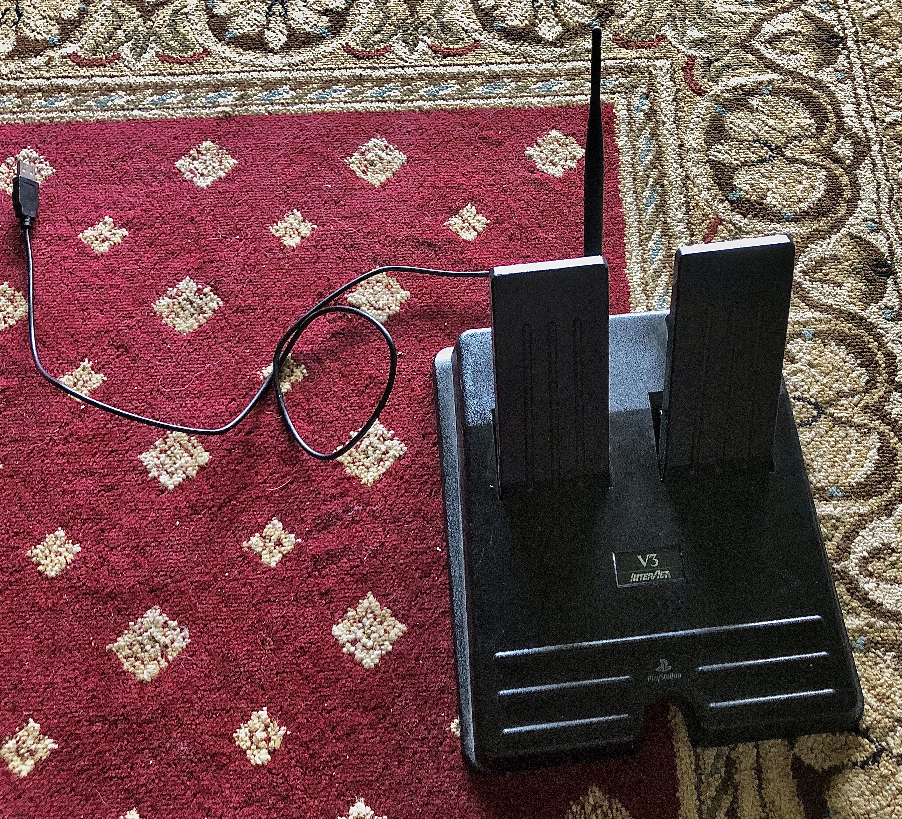
The resulting code can be uploaded using the `ampy` command above, but substituting `hid_services.py` for `main.py`. Once the ESP32 is restarted, it should go into Bluetooth advertising mode, where it can be paired from Windows. I haven't been able to get Linux applications to recognize it yet, though I can pair with it. You may also see a dead zone at the start of the pedal's range of motion, which can be fixed by unscrewing the potentiometer mounts and turning it a bit to enter the range of motion. Once I had everything set up, I closed up the case, leaving an antenna out the back and a power cable for the ESP32:
If you encounter any issues, feel free to leave a comment and I'll do my best to address it.
Discussions
Become a Hackaday.io Member
Create an account to leave a comment. Already have an account? Log In.