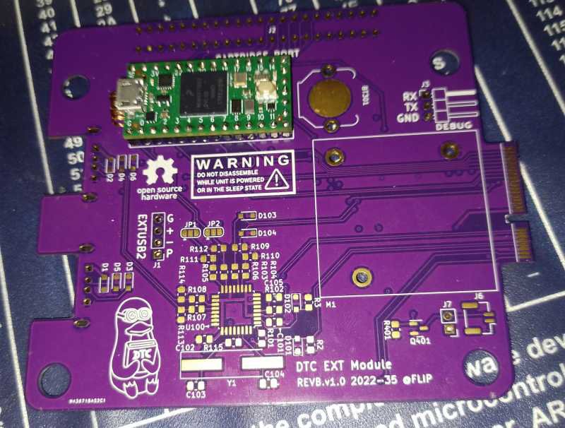
In this post, we explore the process of soldering all of the Teensy4.0s' pins. Yes, all of them, even the SD card ones.
First, the setup: I got a Weller WE1010, with a brand new 0.4mm conical tip heated up to the maximum of 450°C. I chose a very high heat for two reasons: First, the thermal transfer is very much bottlenecked by the fine tip, and secondly I'll be burning off the coating on the enameled copper wire with the iron. The wire diameter chosen was 0.4mm, which might be the first mistake but worked barely.
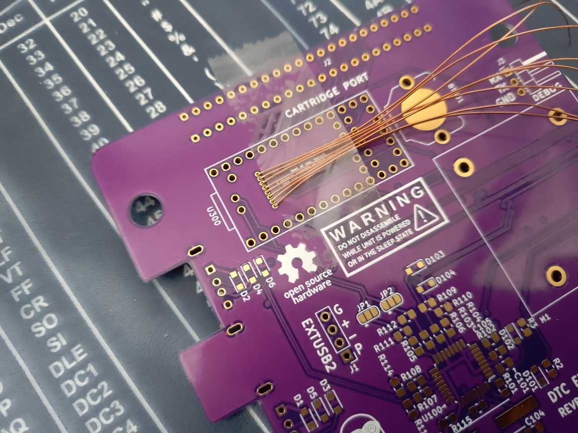
First, the most problematic SD port wires were cut with length to spare, inserted and taped down on the chip side. My use of ordinary tape did work out in the end, but Kapton is obviously the way to go there if you got it.

Then, the wires were soldered on the other end. The trick is to use too much solder with plenty of flux, and wipe the excess using a desoldering braid.
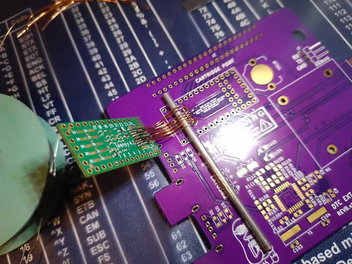
Once those were fixed in place, I then started by soldering the USB host pins, those were relatively easy. Now the Teensy4.0 was fixed in place which turned out to be of help. Then, I tackled the SD card pads. First, cutting the wires to length using my best judgement, it turned out to be a bit too long. After that, the wires were soldered on. I then proceeded to bend the wires using a 3mm round stock in hopes that this eases the strain later when bending the wires down.

Now, the easier pads on the left remained. I needed to cut those wires extra long so that they reach the designated holes while in this position. The excess will be cut when bending the board into position. After that, the pin headers were added.

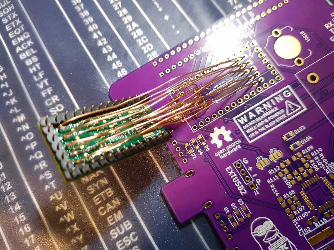
Then came the nerve-wrecking part, bending it all into place. With a slow and steady pace, the Teensy was brought into position. I didn't felt anything snap off which was a good sign.
Now the part where it all fails: The wiring takes up too much vertical space! The thinner 2mm spaced headers were not seating flush. Disappointing to say the least. The choice of 0.4mm wire was bad after all, not to mention the necessity to solder these pins in the first place. After checking the fit within the DevTerm, it stands too tall and the case still flexes. All in all, the operation was a failure. But I'm hopeful that all the connections held up in the process. Testing later will either confirm or deny that. What is certain tough that this process is way too hard. I wouldn't want anyone to spend hours deadbugging a Teensy and then let them pray nothing snaps when flipping it.

What to do next? There are two options: Redesign the board into a whole new revision, or print a backshell for the DevTerm that has the clearance for the Teensy. The latter may be okay temporarily, but no way I'm calling this done with that design flaw.
I already have a few ideas for a new board. Most likely solution is to use the Teensy4.1, which would be challenging due to its size but is the most doable option. Then there's the crazy option: cutting out the space within the Teensy to allow access to the bottom pads, but again, not the way to go as the SD card pads are still not easy to solder. Then, there's the option of just using the chip directly and letting a fabricator solder in all the parts. Out of my league to say the least.
Finally, some good news regarding software: The Linux driver is coming together: I2C works fine, not fast but acceptable. Support for all the UARTs is in the works currently and SPI will be added later.
 flip
flip
Discussions
Become a Hackaday.io Member
Create an account to leave a comment. Already have an account? Log In.