 WJCarpenter
I had a dream of a fairly simple control arrangement for the fans. Since most fans don't switch off at 0% PWM duty cycle, I designed in an N-channel MOSFET to cut the ground link to the fan when I wanted to turn it completely off. That was a grand idea until I wired it up on the breadboard and found that the fan kept gently turning even with the MOSFET switched off. Hmmm. Maybe the reason is obvious to someone who does electronics for a living, but I never completely connected the dots. I did figure out experimentally that the fan shut off completely if I disconnected both the PWM input and the tach output. My theory is that fan motor was getting enough leakage to ground through those lines to give it a feeble spin.
I first attacked the PWM input line. Instead of connecting it directly to the fan PWM line, I connected it to a 2N3904 NPN transistor. The PWM signal went to the base, the collector went to 3.3v, and the emitter went to ground. I also tried it with emitter and collector swapped. Both ways worked in the sense of controlling the PWM to the fan, but it didn't affect the fan slowly turning at 0% PWM. (This arrangement acts as a sort of inverter of the PWM signal, so I had to subtract the desired value from 100% to apply to the control line. I could also have just marked the pin inverted in the ESPHome config, but that made some other parts less clear.) I eventually found that ESPHome would let me explicitly turn off the PWM signal output, and that would stop the final piece of fan movement (again, as long as the tach line was not connected).
(I also tried connecting the same power control from the MOSFET to the base of the NPN to try to disable the PWM signal going through the emitter/collector pins. That didn't work, but I didn't pursue it.)
One down, one to go.
The tach signal is trickier. The same approach doesn't work for that. I'm using the ESPHome pulse_counter component, and there's no way to explicitly switch it off, probably because it's an input signal. I tried the same tricks as for the PWM signal, but they didn't work.
While experimenting, I "cooked" 2 ESP32 boards. When that happened, I thought maybe the boards weren't really happy with my 12v inputs to the 5v ESP32 power pin. I changed things to run the fans off 12v and the ESP32 from the USB connector. My plan was to figure out some kind of power conditioning later, but I have more or less concluded that I killed the boards by feeding them some variation of a 12v tach signal on the ESP32 3.3v GPIOs. Why did it kill things now instead of over the last couple of weeks of messing around with that 12v signal? I hypothesize that there wasn't enough current at 12v to do damage, and something in one of my experiments let more current through on the same line. (That might have happened by me mis-wiring something as I moved jumpers around. No smoke came out, but some parts of the ESP32 boards got pretty hot.)
After burning up the second ESP32 board, I decided on the irrational course of trying to figure out what I should do instead of poking electricity into places where it didn't want to be. Looking through all my notes about fan interfaces, I re-read this StackExchange reply from Michael Karas. It's a clear explanation, and includes helpful info in the comments below the posting. I don't know the original source of the circuit diagram he posted. It's the same as the circuit given in this blog by a different author, who describes it as a "detailed portion of a bit old official motherboard schematic" and gives the missing value for R251 as 4.7k. It's not from the 2005 version of the Intel spec for PWM fans.
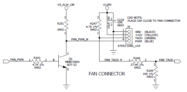
When I read it a while back, I thought, "Nice, but I don't need anything this complicated." It turns out I do need something that complicated. The PWM part of the circuit is pretty much what I ended up with. I wired up the tach part on the breadboard according to this schematic, and it worked as desired.
The fan stops when I want it to stop if:
- I wire things up as in that schematic.
- I use the power control line on the MOSFET to sever the ground link.
- I use ESPHome's explicit turn_off call on the PWM signal when it goes to 0%.
- I take into consideration the signal inversion on the PWM signal.
Discussions
Become a Hackaday.io Member
Create an account to leave a comment. Already have an account? Log In.