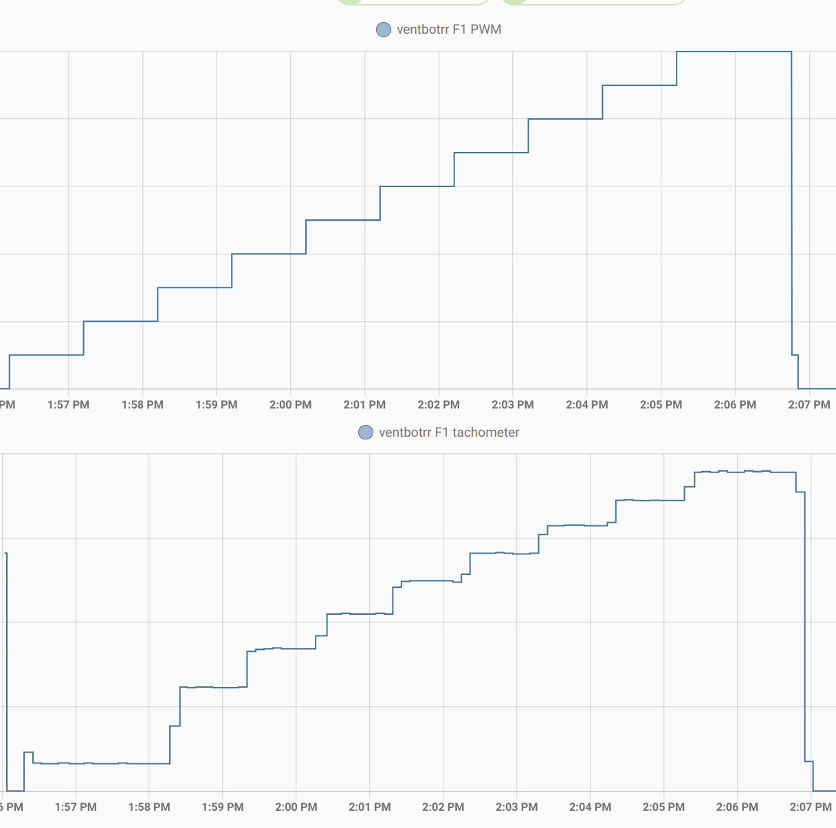
With things wired on the breadboard as described in my last project log, I decided to see how things looked. I configured my ESPHome configuration to step up from 0% to 100% PWM in 10% increments. At each step, I waited for 60 seconds to give the fan speed time to stabilize. I logged the tach output every few seconds, with the fan pulse counts converted to RPMs. On the "PWM" line, I logged both the percentage from the point of view of the user and also the decimal fraction of the inverted signal, which is what is sent to the ESPHome LEDC control.
The results are in rough agreement with what I measured on my scope a few weeks ago.
PWM: 0.90   10
  tach:  150 rpm
  tach:  164 rpm
  tach:  162 rpm
  tach:  164 rpm
  tach:  165 rpm
  tach:  161 rpm
 -----
PWM: 0.80   20
  tach:  237 rpm
  tach:  362 rpm
  tach:  363 rpm
  tach:  359 rpm
  tach:  363 rpm
  tach:  362 rpm
 -----
PWM: 0.70   30
  tach:  459 rpm
  tach:  620 rpm
  tach:  621 rpm
  tach:  620 rpm
  tach:  624 rpm
  tach:  620 rpm
 -----
PWM: 0.60   40
  tach:  708 rpm
  tach:  851 rpm
  tach:  852 rpm
  tach:  851 rpm
  tach:  855 rpm
  tach:  854 rpm
 -----
PWM: 0.50   50
  tach:  930 rpm
  tach:  1062 rpm
  tach:  1059 rpm
  tach:  1058 rpm
  tach:  1059 rpm
  tach:  1058 rpm
 -----
PWM: 0.40   60
  tach:  1131 rpm
  tach:  1247 rpm
  tach:  1253 rpm
  tach:  1251 rpm
  tach:  1254 rpm
  tach:  1250 rpm
 -----
PWM: 0.30   70
  tach:  1313 rpm
  tach:  1419 rpm
  tach:  1418 rpm
  tach:  1416 rpm
  tach:  1418 rpm
  tach:  1418 rpm
 -----
PWM: 0.20   80
  tach:  1482 rpm
  tach:  1583 rpm
  tach:  1581 rpm
  tach:  1583 rpm
  tach:  1590 rpm
  tach:  1589 rpm
 -----
PWM: 0.10   90
  tach:  1646 rpm
  tach:  1737 rpm
  tach:  1736 rpm
  tach:  1744 rpm
  tach:  1740 rpm
  tach:  1744 rpm
 -----
PWM: 0.00   100
  tach:  1804 rpm
  tach:  1913 rpm
  tach:  1911 rpm
  tach:  1913 rpm
  tach:  1917 rpm
  tach:  1913 rpm
Here is a nice graphical result from a later similar test.

 WJCarpenter
Discussions
Become a Hackaday.io Member
Create an account to leave a comment. Already have an account? Log In.