 Ted Yapo
So, I think the VGA generator design is complete - enough so that I ordered components and adapter boards for the SMD parts:
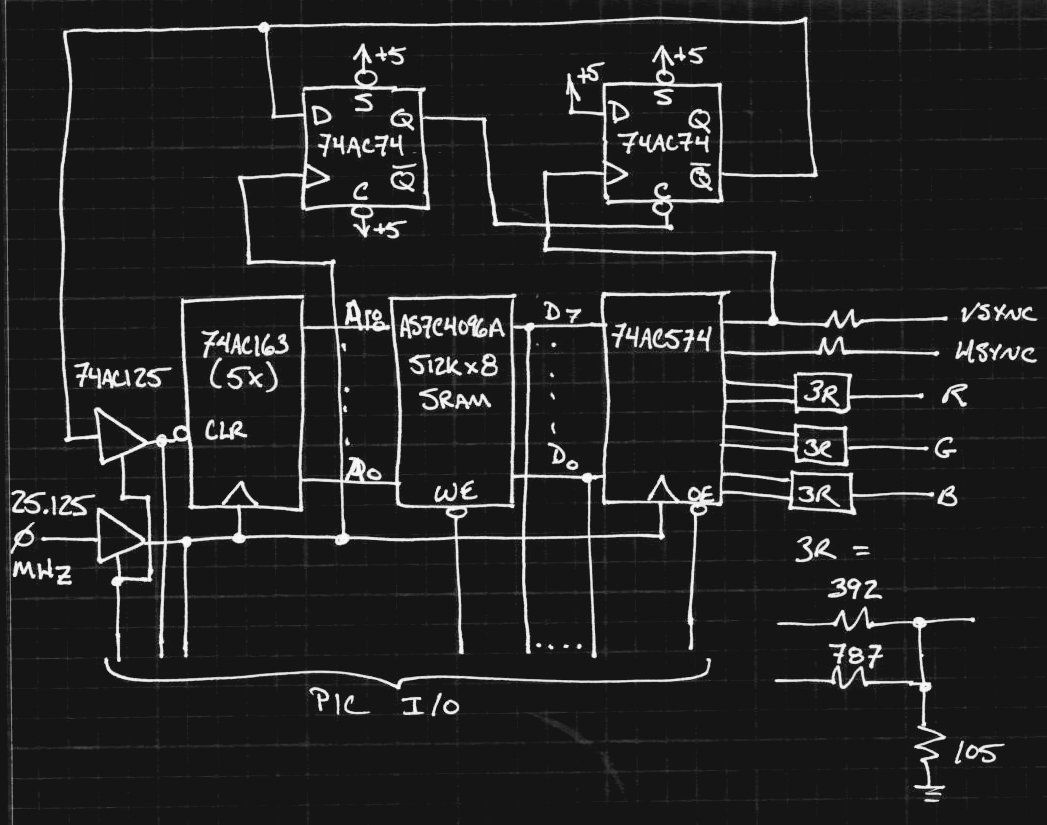
The 19-bit address for the SRAM is generated by (5) 74AC193 synchronous counters. The reset circuit was an interesting one to design - the address resets to zero on the rising edge of VSYNC, using an edge-triggered 74AC74 d-flop to hold the counter clear line until the next clock edge - the '163 has a synchronous reset. On the same edge, a second d-flop clears the first one to prevent another reset until the next posedge of VSYNC. This edge-triggered reset is required because the vertical sync line is high (also low, for the actual sync pulse) for a number of dot clocks per frame.
This arrangement means the data has to be rotated in the SRAM address space a little, but that's just some PIC code.
A pair of 3-state buffers (74AC125) multiplex the counter clock and reset lines between the generator circuitry and the PIC. On the data lines, the SRAM already has 3-state outputs. In total 13 I/O lines from the PIC are required. The PIC doesn't connect the address lines directly - it has to reset and increment the counter to access the RAM. I'm willing to accept this since it saves multiplexing 19 lines.
The clock multiplexing is asynchronous - so there could be a runt pulse generated when the PIC first enables the VGA output, but if it holds the reset line until after the clock is established, this should cause no harm.
I ordered a PIC16F1718 as a candidate processor - it has 2 kB of RAM, which might come in handy, and the rest of the niceties of the modern mid-level PICs. I chose this one because it looks like it will drop right in to some development boards I made for the older PIC16F723A's, which would be very convenient.
I designed some ugly-smd adapters for all these (SOIC) parts. I figure it will be a good test of the prototyping system to see if it can run at 25 MHz. Worst case, I'll wire all the signals with 30-gauge kynar twisted pairs (100 ohms impedance) with series terminations right on the adapter boards. It probably won't be necessary.
Overall, it's 8 ICs plus the RAM (and the PIC, which could be any microcontroller with 13 I/O lines). I think I initially said 5, meaning 10, so it's basically what I thought :-)
UPDATE 20161206
Since I'm only using two of the four 3-state buffers in the 74AC125 package, I might try adding the remaining two in parallel to make "super drivers". These are the lines with the greatest fanout (7 for CLK and 4 for CLR), so a little extra drive probably won't hurt.
Also, instead of a too-clever sequencing solution to switching over control of the CLR line, I'll add a weak pullup to hold the state while control is switched over. I read on Wikipedia that this is done on PCI buses.
Discussions
Become a Hackaday.io Member
Create an account to leave a comment. Already have an account? Log In.
OK it's not as hard as I thought:
http://ece320web.groups.et.byu.net/labs/VGAController/VGAController.html
"For the 640x480, this counter should count from 0 to 799 (i.e. 640 displayed pixels, 16 front porch pixels, 48 back porch pixels, and 96 "pulse" pixels)."
Multiplication by a constant 800 is not hard. It's 32×25, or ((y+y+x)<<3)+y)<<5
Are you sure? yes | no
I already need 16x16 multiplies for generating the images in 16-bit fixed point, so basically the x800 part comes for free :-)
Are you sure? yes | no
Are you calculating some Mandelbrot, huh ? :-D
Somebody wrote the suitable code for the YASEP and it's just incredible...
Are you sure? yes | no
@Yann Guidon / YGDES Yeah, I have the Mandelbrot code done - it's a trivial algorithm, even if it takes a while to run. And, it only needs addition, subtraction, and multiplication, which are easy in fixed point. I think it will fit with the VGA generation code in 1 kB even compiled from (tweaked) C-code. I don't have the target PIC yet, but I can try it on a different one - sending results over the serial port for now.
I really want to get a simple ray-tracing program going, but it requires division and square-root. Floating point on the PIC is way too big for 1kB, so if I can fit the compiler's integer division and get a decent integer square root routine going (I'm looking at a few now), I just might be able to do it, but it won't be easy. Nice to have stretch goals...
Are you sure? yes | no
Ah...
http://www.epanorama.net/documents/pc/vga_timing.html
http://users.wpi.edu/~rjduck/vga_controller_640_60.vhd
There are 800 px horizontally but 525 lines vertically...
Are you sure? yes | no
I'm slowly "getting it"...
To accelerate the "addressing", you can select (with 5 PIC lines) which counters to increment. OK that makes some more MUXing but you can get faster anywhere in the RAM without using much more I/O lines :-)
Can the PIC "sense" when there is a Vsync or Hsync to write in the RAM ?
Are you sure? yes | no
You could also "multiplex" the RAM address, from the 8-bits data port, for the price of maybe 4 PIC lines (2 latch enable and 2 /OE) and a couple of latches (573/574)
Are you sure? yes | no
Another thought : you could simplify some addressing things with a "segmentation" of the address counters :-)
VGA = 640×480 (plus some more) so if it fits in 1024×512, you can use a 10-bits counter for the lines, and a 9-bits counter for the columns, each with the flip-flop reset trick. This simplifies line address calculations for your program, no weird multiplies, just a couple of Vblank and Hblank offsets...
With multiplexing, you can keep the counters counting normally, which drastically reduces the tears/wobbles on the screen.
Sorry for over-engineering it ;-)
Are you sure? yes | no
That's what I suggested previously to split off the ripple counter to reduce the settling time.
Take a look at bus-hold logic.
http://www.ti.com/lit/an/scla015/scla015.pdf
Are you sure? yes | no
The pixel addressing isn't that bad: for a pixel at (row, col), address = offset + row * 800 + col. It's just like accessing a rectangular sub-region of a normal mapped image in memory - you see these offset and stride variables in image library structures all the time for "views" into an image. @K.C. Lee mentioned a segmented address counter idea a while back. It's an interesting thought - the idea was that it might simplify the speed problem.
Oh, image tearing? No it's not going to tear, it's going to blank while the PIC generates the image - it's not a live display, just generate one frame and display it. Maybe I'll make it do more than one, but it's not going to update them live. I'm trying to make it as simple as possible - especially the hardware.
Actually, I can put the monitor in power-save by writing the state of the sync lines - if I disconnect the output register clock separately from the counter clock. That's interesting :-)
Are you sure? yes | no
OK I get it... you're not doing an actual video card, sadly :-P
Are you sure? yes | no
Yes, that sums it up - it's not a video card. Mostly because I am afraid of feature creep - I've had too many projects get stuck because I added too much, too fast. If I can get the basics of the display to work, then maybe a second or third version could aim at a really usable adapter. Or, someone else can add the other 20% (80% ?) that makes it "complete".
I think at that point, it's SPI RAM and/or FPGA or other modern parts. I just couldn't do that for the 1kB contest :-)
Are you sure? yes | no
Ah hah. Two 7474 halves... confused me 'till you explained. I thought I read that the 640x480 standard has two lines of Vsync, so thought you were doing a counter/delay, but I get it now... And only one *pixel* clock-pulse, rather than one Vsync. Clever. Maybe this is what I need for sdramThing's one-shot circuits.
Are you sure? yes | no
There's a better way to do one-shots in this sample book-chapter PDF (pages 17 & 18):
http://www.springer.com/cda/content/document/cda_downloaddocument/9781461403968-c1.pdf?SGWID=0-0-45-1223841-p174125174
Mine is pretty kludgy, but I didn't want to add another package just to get a single AND gate.
Are you sure? yes | no
sdramThing's one-shots are already designed and functional, so I'm only looking into the concept further when I stumble across it. But I've saved that link until *after* I ever design a board ;)
Are you sure? yes | no
Oh, I meant better than the way I did them. I'm sure the sdramThing's one-shots are plenty good :-)
The link is pretty good, but it's written for IC designers - like a lot of electronics texts these days. So, adding an extra gate or two is free. For me, it's another package or two.
Are you sure? yes | no
Yeah, the whole thing is pixel clocks - and there's a byte in the SRAM for every clock period in the whole waveform. I think the end of the vsync pulse has to be one pixel clock early, but that shouldn't matter.
Are you sure? yes | no