 J Gleyzes
EC is the abbreviation for Electro Conductivity. It is used to determine the nutrient concentration of the solution. This factor is essential to optimize the soilless culture. Indeed, the nutrient concentration will not be the same for a seeding as for a flowering plant, or lettuce needs less nutrient than tomatoes.
Let's get started! Let's add an EC sensor to UltraTower.
There are many EC sensors on the internet ranging from 10€ to over 200€. We will make one with 4 components + the ESP32.
Schematic:
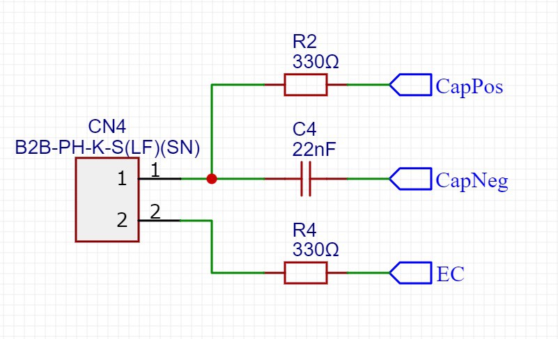
2 resistors, 1 capacitor and an EC probe which is immersed into the solution. That's all!
The values of the components are important, the code of the ESP32 must be modified if you change them.
What is the code doing?
There are 6 steps in the code to read the EC value but also to reverse polarity to avoid probe corrosion.
The ESP32 changes the state of the 3 pins during the 6 steps here is what the code does.
The EC is measured in step 2 here is the code:
    endCycle = 0;
    startTime = micros();
    pinMode (CP_PIN,INPUT);
    startCycle = ESP.getCycleCount();

    attachInterrupt(CP_PIN, isrCountEndCycle, FALLING);
    digitalWrite(EC_PIN, LOW);
    pinMode(EC_PIN, OUTPUT);
    while (endCycle == 0) {                   // endCyle gets set in the ISR, when an interrupt is received.
      if (micros() - startTime > EC_TIMEOUT) { // Time out - in case sensor not connected or not in water.
        timeout = true;
        break;
      }
    }
    detachInterrupt(CP_PIN);
    if (timeout) break;
    dischargeCycles = endCycle - startCycle;
    totalCycles += dischargeCycles;
The capacitor discharges into the two resistors, one of which passes through the probe. The ESP32 detects when the state of the CAPPOS pin changes from HIGH to LOW and triggers this function :
void IRAM_ATTR isrCountEndCycle() {
     endCycle = ESP.getCycleCount();
}
The number of CPU cycles of the ESP32 is calculated in order to have an accurate and reproducible discharge time.
Then we have to make solutions of different EC to calibrate the sensor.
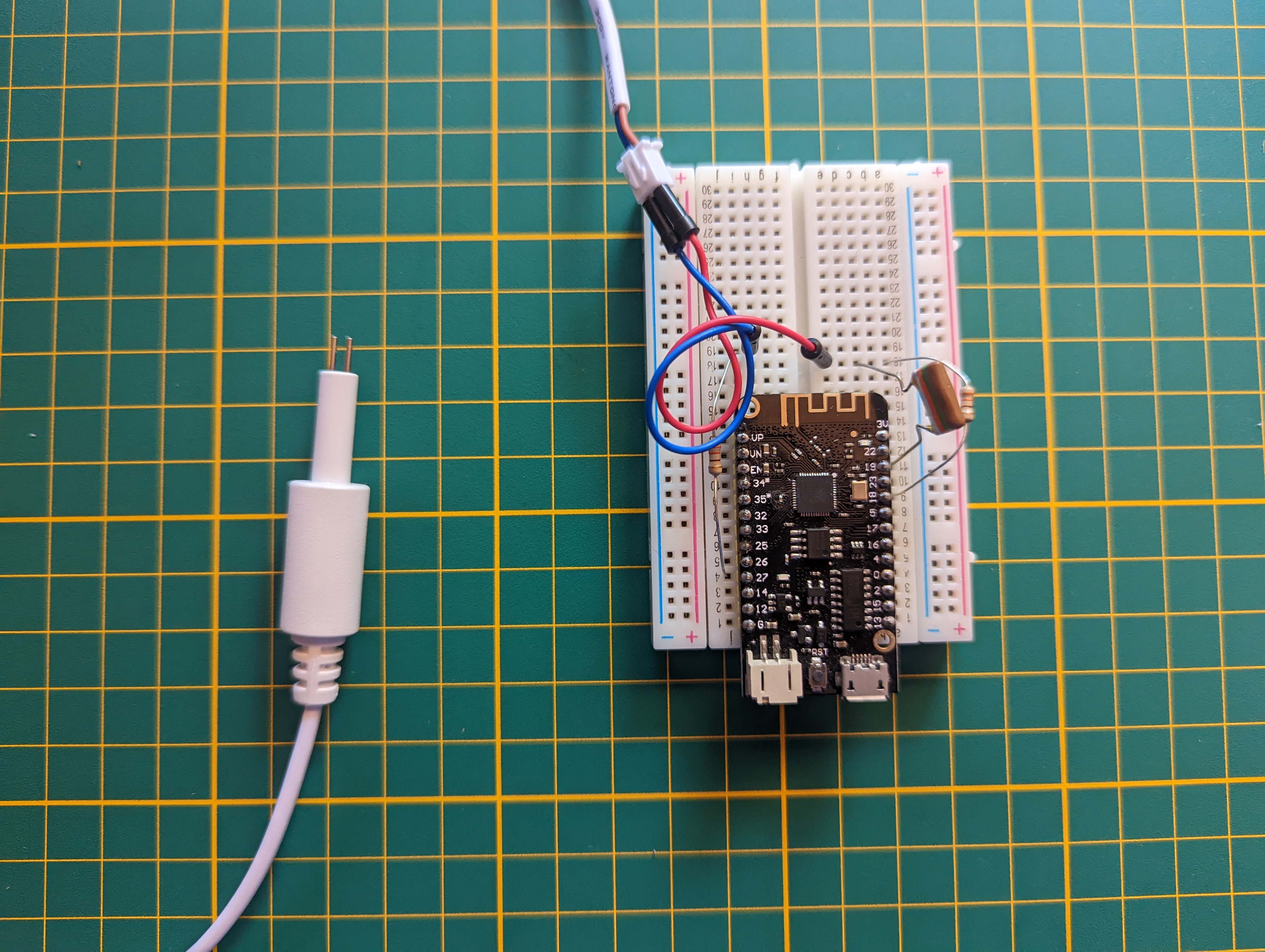
Here is how we made an EC sensor for less than 5€.
The EC sensor will be added to the next PCB to analyse water quality as foreseen in the UltraTower functional block diagram.
Here is the whole code adapted from this project:
#define CP_PIN 18
#define CN_PIN 19
#define EC_PIN 27


// Time constants in MICROSECOND !
#define CHARGEDELAY 36                        // Time in microseconds it takes for the cap to charge; at least 5x RC.
                                              // 22 nF & 330R resistor RC = 7.25 us, times 5 = 36.3 us.
#define DISCHARGEDELAY 14                     // Discharge the cap before flipping polarity. Better for the pins. 2xRC.

#define EC_TIMEOUT 2000                       // Timeout for the EC measurement in microseconds.
                                              // 2 ms half cycle --> 250 Hz.


uint32_t readECSensor() {

  uint32_t dischargeCycles = 0;               // The number of clock cycles it took for the capacitor to discharge.
  uint32_t totalCycles = 0;                   // The cumulative number of clock cycles over all measurements.
  uint32_t startCycle;                        // The clock cycle count at which the measurement starts.
  uint32_t startTime;                         // The micros() count at which the measurement starts (for timeout).
  bool timeout = false;
  for (uint16_t i=0; i < (1 << oversamplingRate); i++) { // take 2^ECSAMPLES measurements of the EC.

    ///////////////////////////////////////////////////////////////////////
    // Stage 1: charge the cap, positive cycle.
    // CAPPOS: output, high.
    // CAPNEG: output, low.
    // EC: input.

    digitalWrite(CP_PIN, HIGH);
    digitalWrite(CN_PIN, LOW);
    pinMode (EC_PIN, INPUT);
    pinMode (CP_PIN, OUTPUT);
    pinMode (CN_PIN, OUTPUT);
    delayMicroseconds(CHARGEDELAY);           // allow the cap to charge fully.

    ///////////////////////////////////////////////////////////////////////
    // Stage 2: measure positive discharge cycle by measuring the number of clock cycles it takes
    // for pin CAPPOS to change from HIGH to LOW.
    // CAPPOS: input.
    // CAPNEG: output, low (unchanged).
    // EC: output, low.
    endCycle = 0;
    startTime = micros();
    pinMode (CP_PIN,INPUT);
    startCycle = ESP.getCycleCount();

    attachInterrupt(CP_PIN, isrCountEndCycle, FALLING);
    digitalWrite(EC_PIN, LOW);
    pinMode(EC_PIN, OUTPUT);
    while (endCycle == 0) {                   // endCyle gets set in the ISR, when an interrupt is received.
      if (micros() - startTime > EC_TIMEOUT) { // Time out - in case sensor not connected or not in water.
        timeout = true;
        break;
      }
    }
    detachInterrupt(CP_PIN);
    if (timeout) break;
    dischargeCycles = endCycle - startCycle;
    totalCycles += dischargeCycles;

    ///////////////////////////////////////////////////////////////////////
    // Stage 3: fully discharge the cap, prepare for negative cycle.
    // Necessary to keep total voltage within the allowed range (without these discharge cycles the voltage would jump to about +1.4*Vcc and -0.4*Vcc)
    // CAPPOS: output, low.
    // CAPNEG: output, low (unchanged).
    // EC: input.

    digitalWrite(CP_PIN, LOW);
    digitalWrite(CN_PIN, LOW);
    pinMode (EC_PIN, INPUT);
    pinMode (CP_PIN, OUTPUT);
    pinMode (CN_PIN, OUTPUT);
    delayMicroseconds(DISCHARGEDELAY);

    ///////////////////////////////////////////////////////////////////////
    // Stage 4: charge the cap, negative cycle.
    // CAPPOS: output, low (unchanged).
    // CAPNEG: output, high.
    // EC: input (unchanged).
    digitalWrite (CN_PIN, HIGH);
    delayMicroseconds (CHARGEDELAY);

    ///////////////////////////////////////////////////////////////////////
    // Stage 5: negative discharge cycle, compensation.
    // CAPPOS: input.
    // CAPNEG: output, high (unchanged).
    // EC: output, high.

    digitalWrite (EC_PIN, HIGH);
    pinMode (CP_PIN,INPUT);
    pinMode (EC_PIN, OUTPUT);
    delayMicroseconds (dischargeCycles / 250);

    ///////////////////////////////////////////////////////////////////////
    // Stage 6: fully discharge the cap, prepare for positive cycle.
    // CAPPOS: output, high.
    // CAPNEG: ouput, high (unchanged).
    // EC: input.

    digitalWrite(CP_PIN, HIGH);
    pinMode(CP_PIN, OUTPUT);
    pinMode(EC_PIN, INPUT);
    delayMicroseconds(DISCHARGEDELAY);
  }
  if (timeout) {
    dischargeCycles = 0;
  }
  else {
    dischargeCycles = (totalCycles >> oversamplingRate);
  }


  // Disconnect the sensor.
  pinMode(CP_PIN, INPUT);
  pinMode(CN_PIN, INPUT);
  pinMode(EC_PIN, INPUT);
  return dischargeCycles;
}
Discussions
Become a Hackaday.io Member
Create an account to leave a comment. Already have an account? Log In.