 Michael Wessel
Demo Videos:
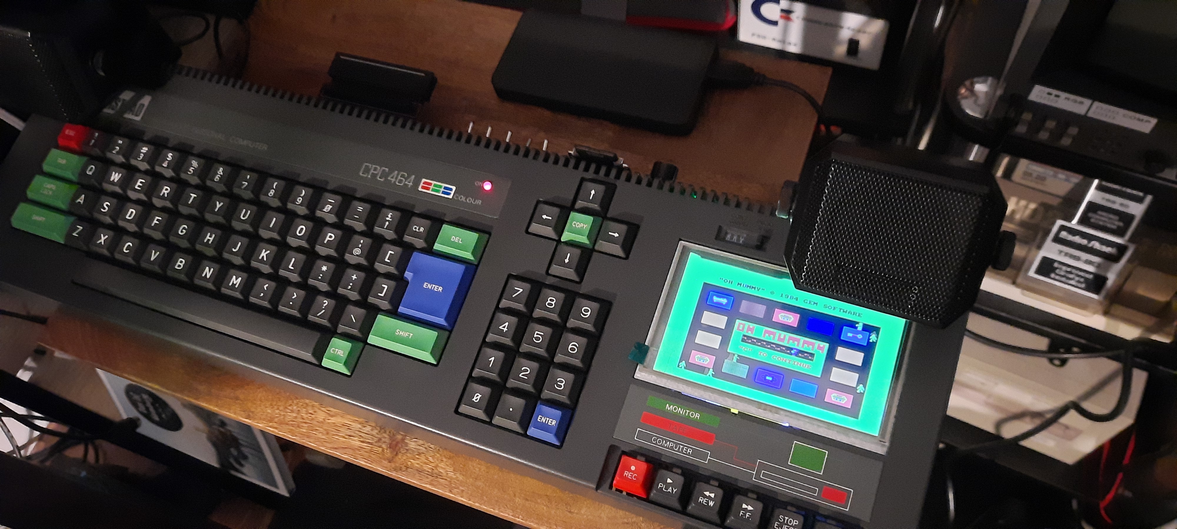
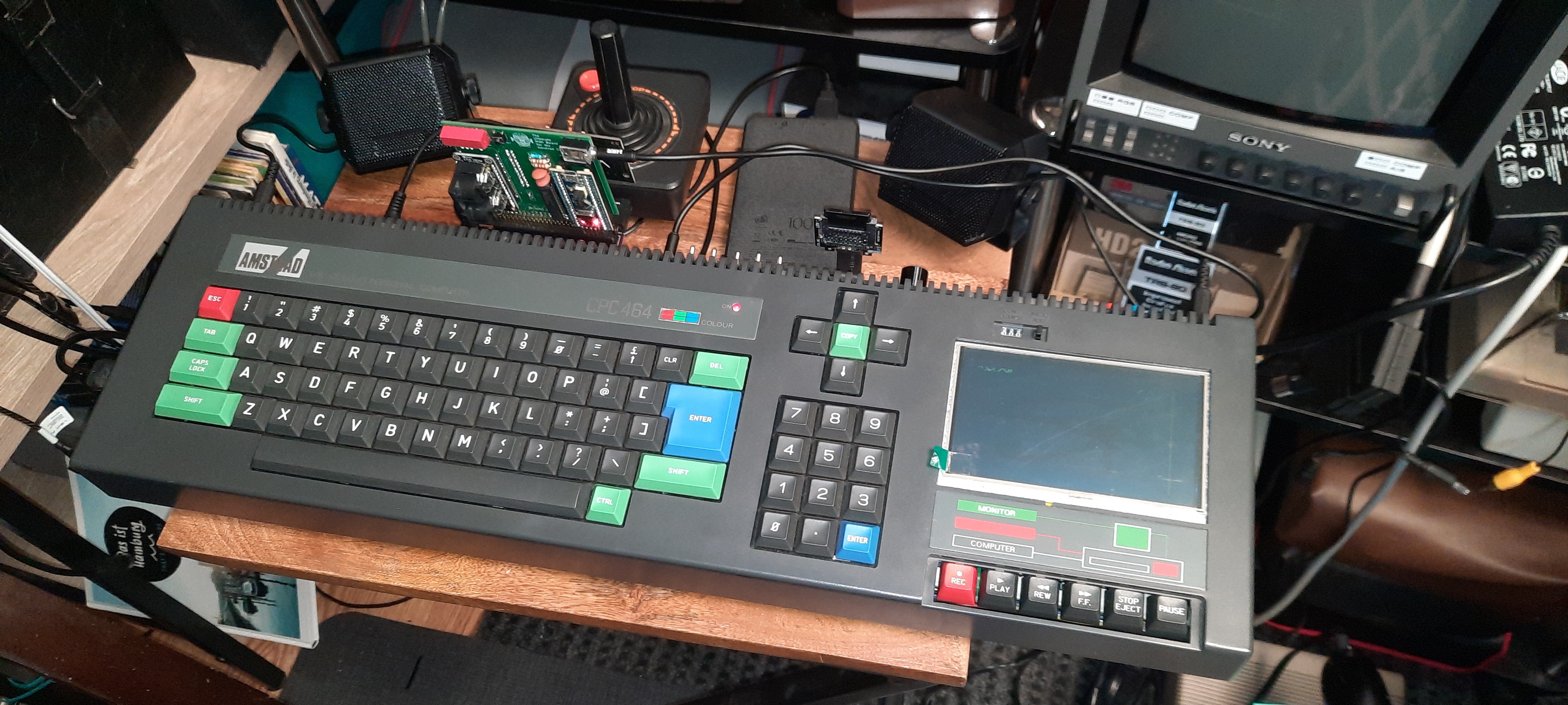
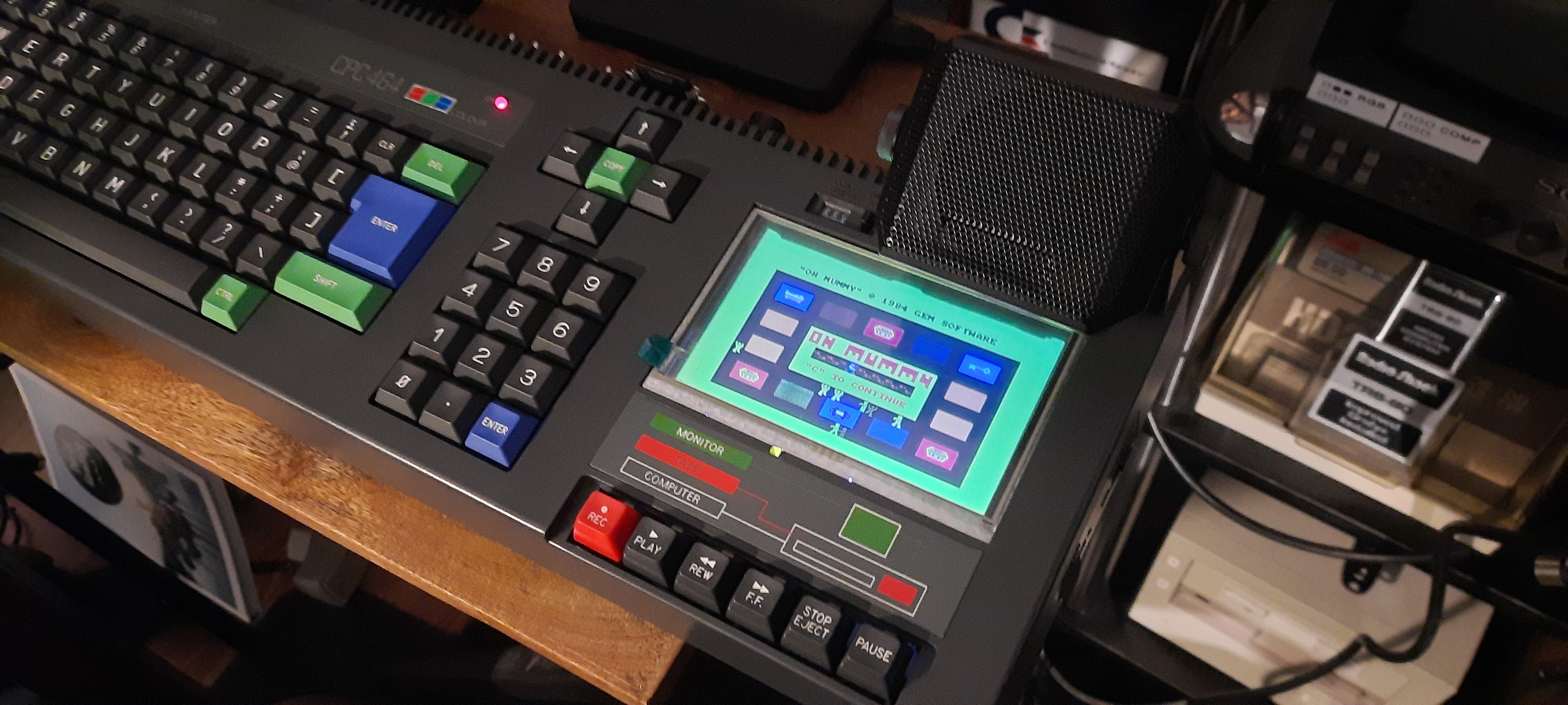
The final CPC Portable playing "Oh Mummy!":
Build Objectives
In principle, I am not a big fan of case mods. Being a collector of retro computers, I strive to restore and preserve the original hardware. This cost-reduced CPC 464 had an irreparable tape drive that was causing "tape salad". Despite all my efforts I wasn't able to fix the mechanics. I tried finding a replacement datacorder for a justifiable price, but was out of luck - CPCs and spare parts are getting quite pricey on eBay lately. Seems we are running out of CPCs in this world!
Hence, having a CPC with defunct datacorder at hand, I had to take the chance and try to realize an old dream of mine - to create a portable CPC based on the authentic original hardware with unobtrusive modifications that would give me a built-in display (instead of the datacorder), and at least an HxC SDcard disk drive emulator plus some extra memory so that it would become "equivalent" to a CPC 6128. The build process is described here on Hackaday; for now, it's just a photo log, but I'll add descriptions over time and I will also create a more extensive YouTube video at some point.
The required case modifications were quite extensive (the Dremel was my friend on this project!), and, as explained, I am usually not a big fan of destructive and irreversible case mods. However, something has to give in order to make this happen. The mods are all unobtrusive in the sense that the resulting CPC Portable is still clearly recognizable as an Amstrad CPC - the original looks and form factor and color scheme, as well as as much as possible of the original hardware, i.e., the motherboard etc. Modifying the overall form factor is a no-go for me. The hardware and case has to be original. I am also not a big fan of modern "re-engineered" CPC motherboards, emulators, Raspberry Pis, or FPGA solutions in a CPC case.
So my main objectives were:
- original motherboard
- original case and keyboard
- add unobtrusive mods and extensions that would add the desired features
- allow for one external CPC extension card ("MX4 Standard")
- add a decent pair of detachable stereo speakers
A CPC in a laptop case, or a re-engineered modern CPC mainboard with extensions already on board, are both no-gos for me, and albeit interesting approaches, it's not what I want or value and I leave these alleys to other project builders. Projects that, for example, remove the number block & cursor keys from the keyboard, and cut off 35% from the CPC case (including the datacorder) just to reduce its overall length to make it more "portable" are not what I strive for, and again, I leave this kind of "retro computer butchering" to others.
Finally, I didn't want to include the batteries within the case. Batteries might only last so long, then need to be replaced (requires opening the case again), are heavy, and most of the time the CPC Portable will be running from the grid anyway. So I decided to leave the battery external. It's a simple 10000 mAh Powerbank which has enough electric energy to power the Portable for a few hours. As shown in the demo video, it can even supply an extension card (Speak&SID).
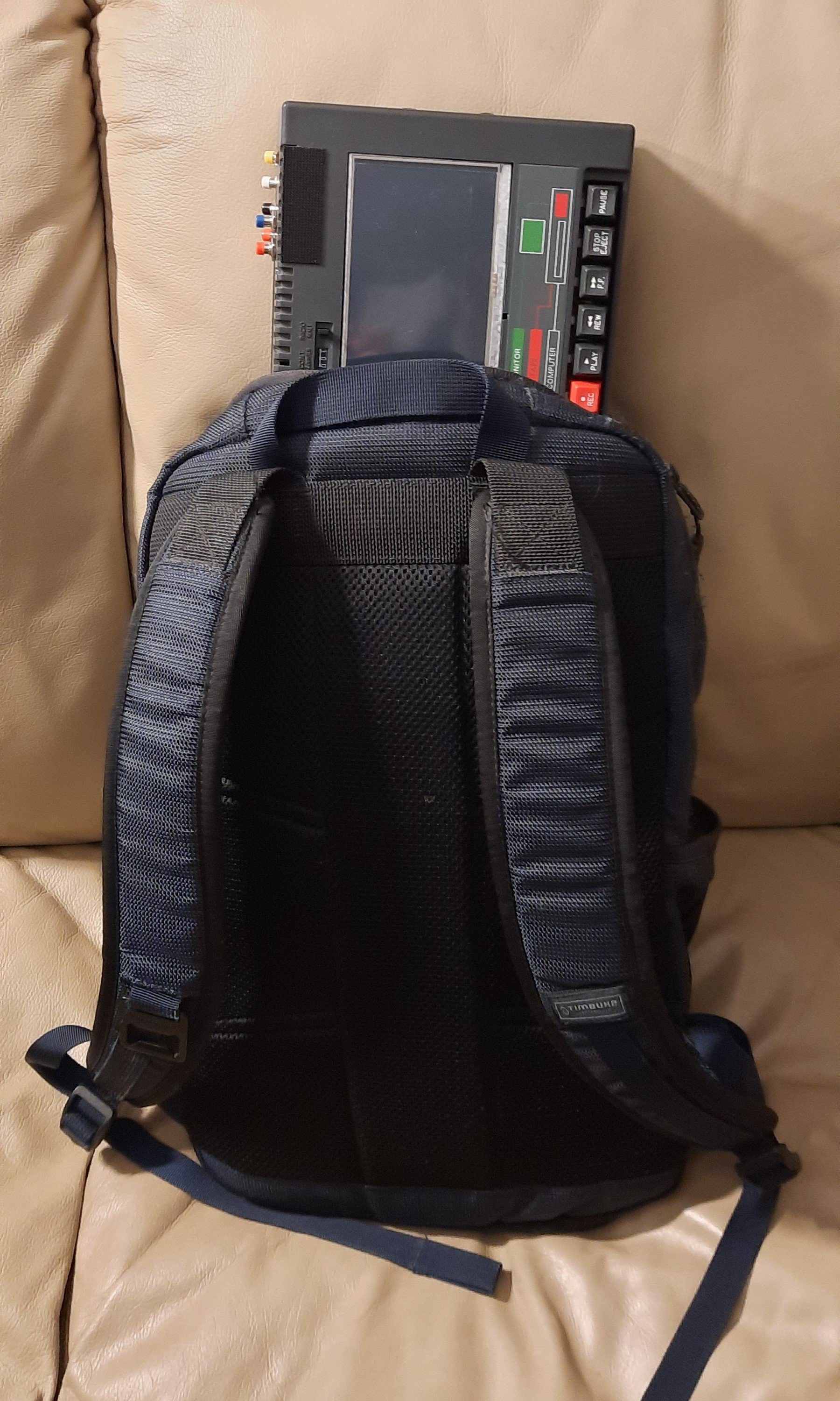
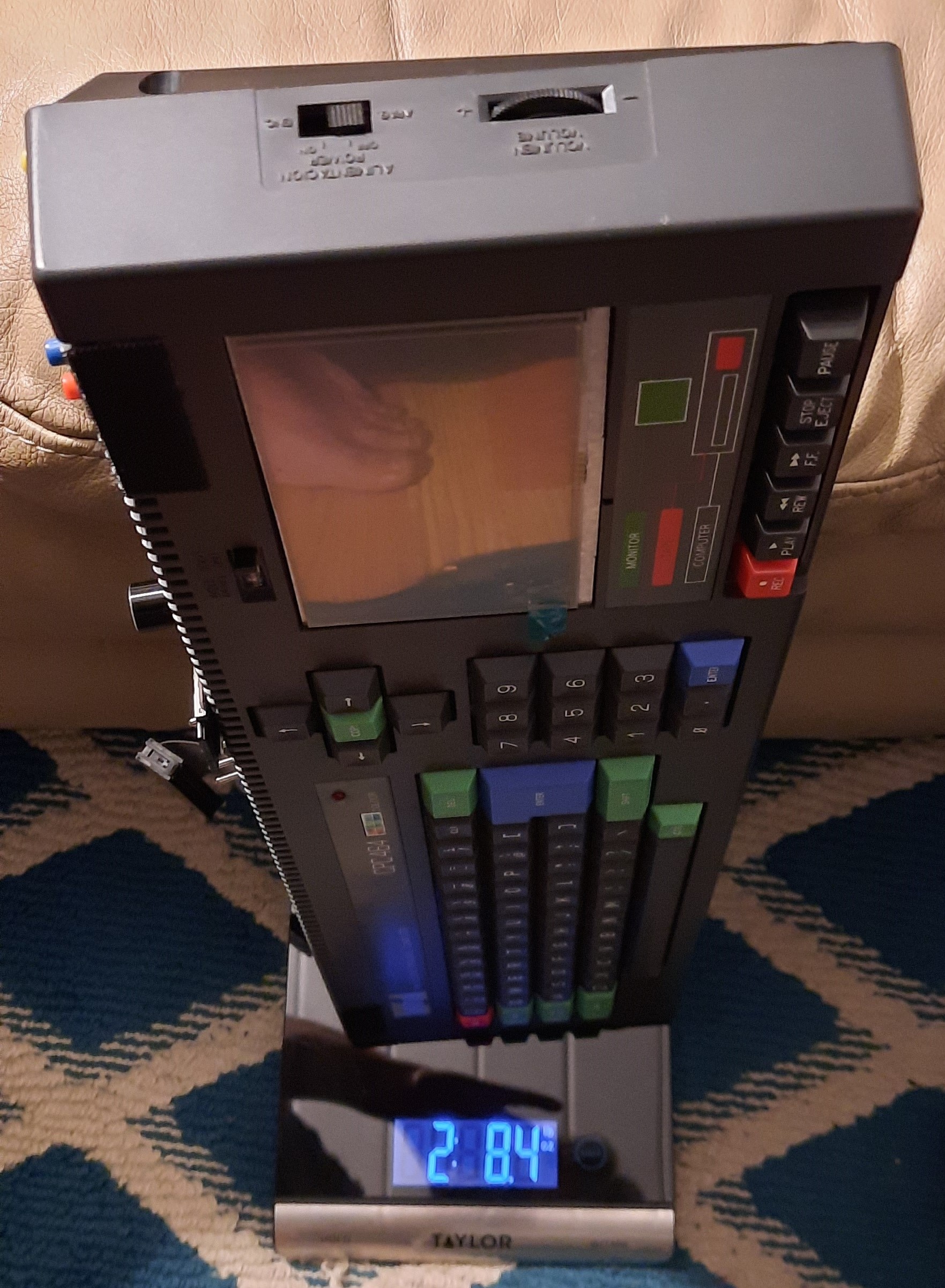
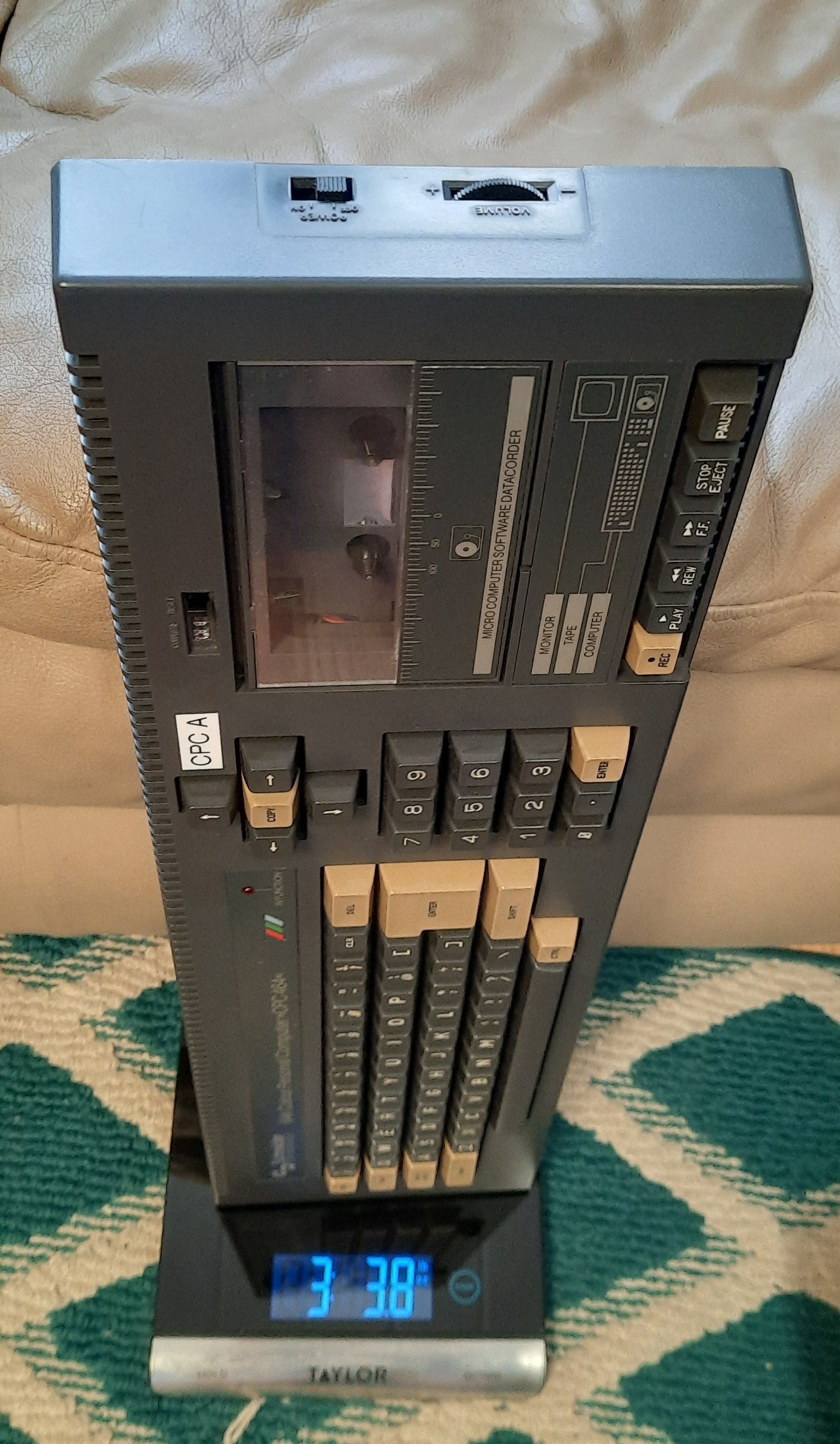
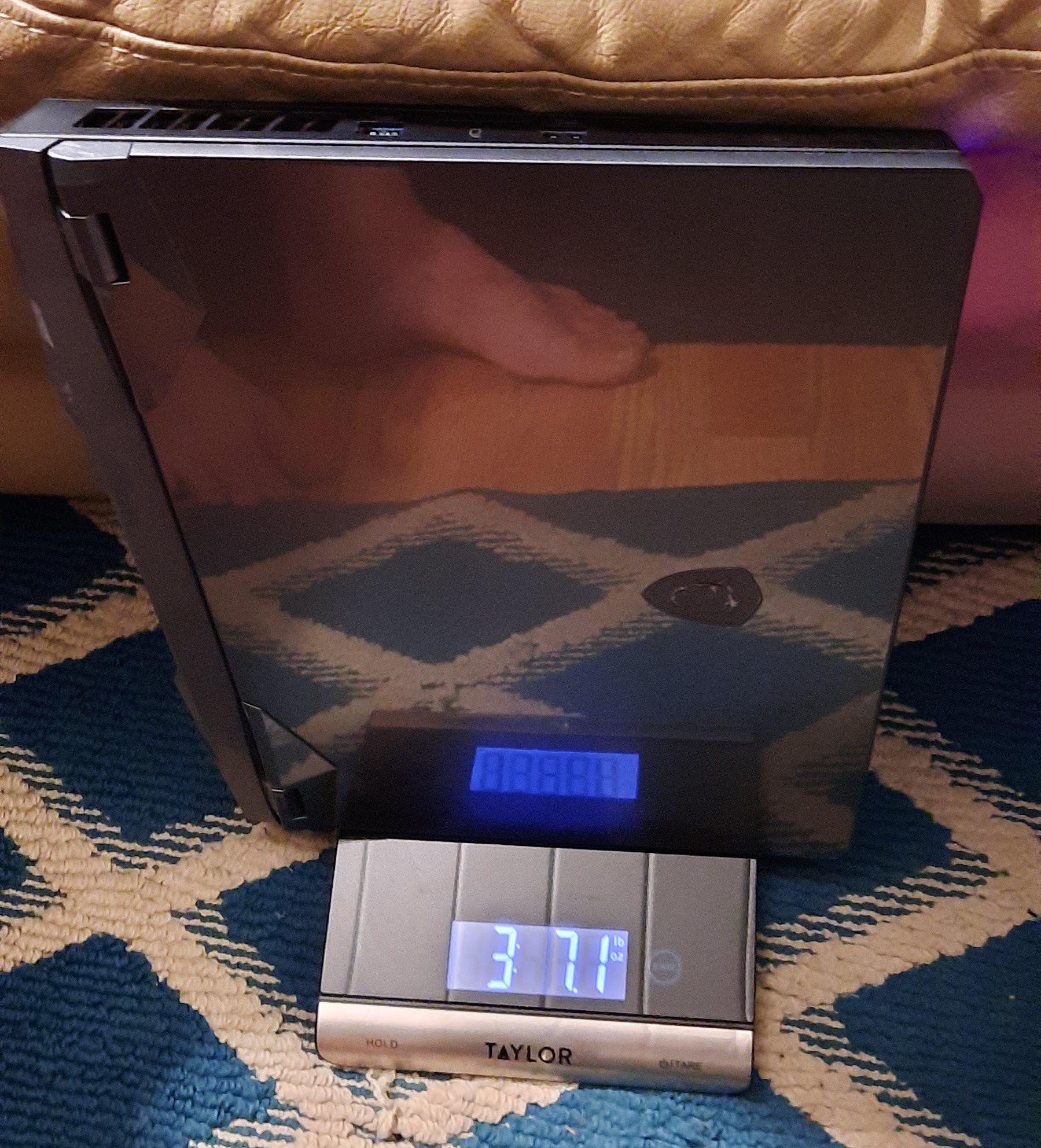
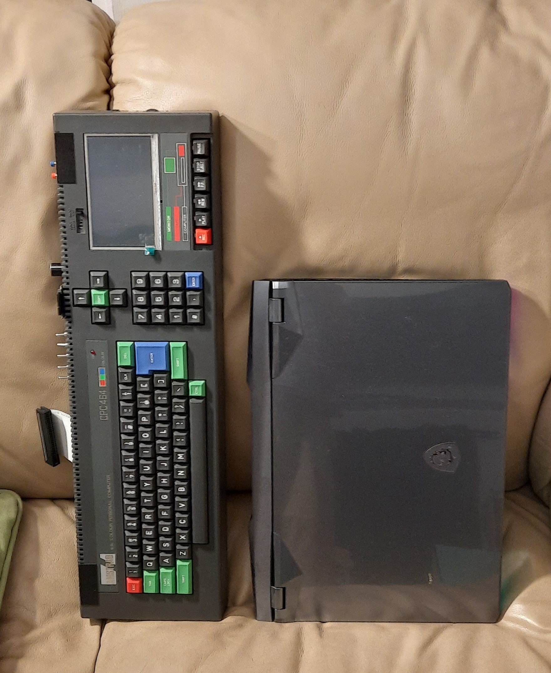
Now, it the CPC Portable really portable? Of course it is! My MSI desktop substitute gaming laptop weighs almost a full LBS more; note that the speakers can be removed easily as well, as they are only attached with Velcro. The CPC also still has it internal little mono speaker. Note that the original CPC 464 with datacorder actually still weighs more than the Portable - the tape drive is "heavy metal!"
Build Process
The original Amstrad CPC 464 had a full-size and very spaciously laid out PCB. My original Schneider CPC 464 which I got for my confirmation in April 1985 probably had a MC0001A (or MC0002B) motherboard:
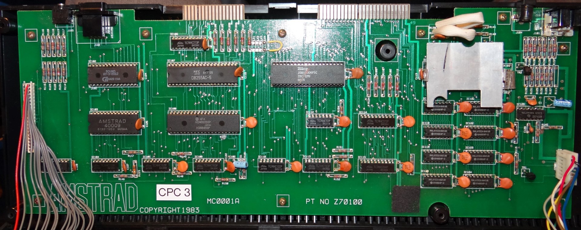
Did Amstrad just waste space? I believe they didn't - before the Ferranti Gate Array became available, they were using a quite large "Gate Array TTL Simulator" board on top of the motherboard (you can find images of the GA Emulator on the Internet), so a large supporting PCB was probably advantageous.
In later years, Amstrad revised the motherboard a couple of times, also to reduce costs significantly; you can find the revision history here:
https://cpctech.cpc-live.com/docs/cpcrev.html
https://www.cpcwiki.eu/index.php/Mainboard_Versions
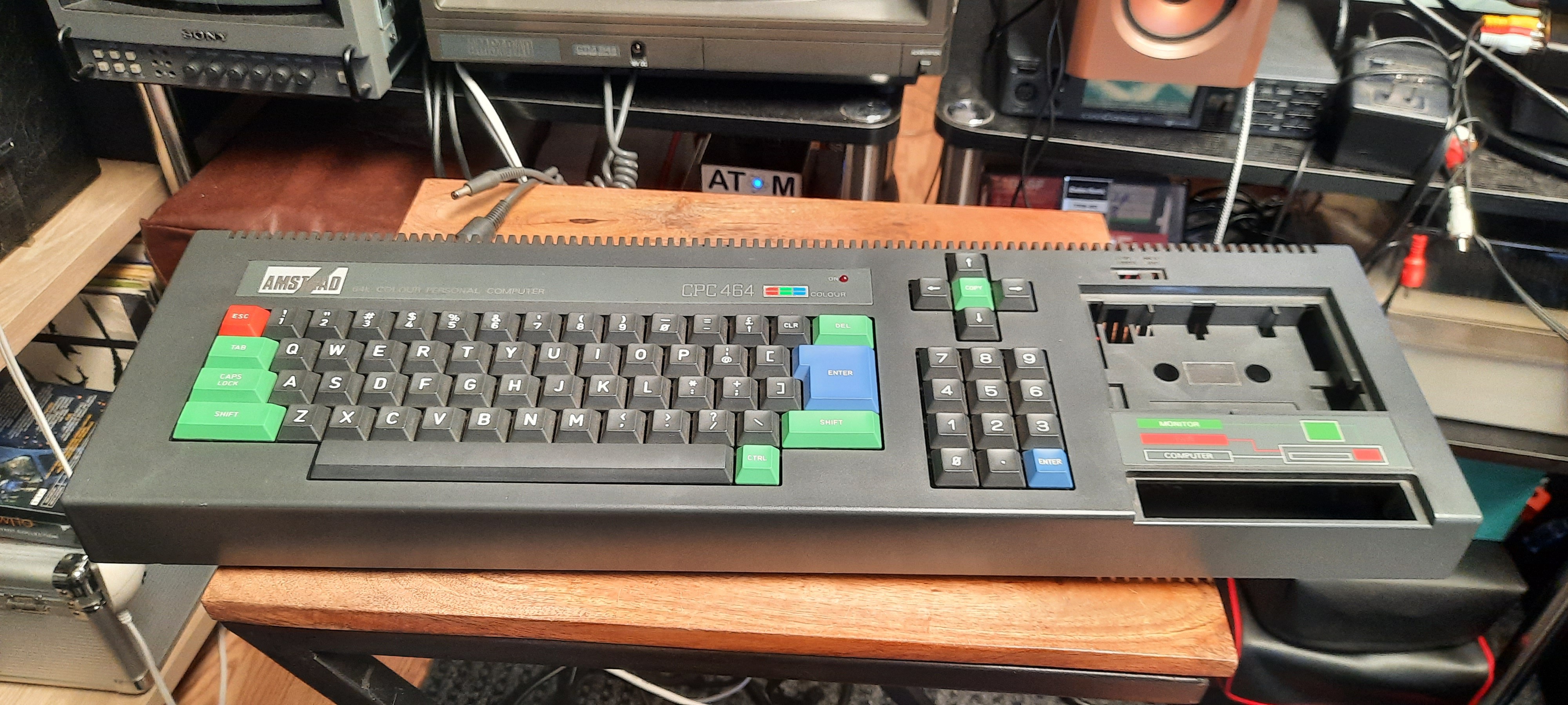
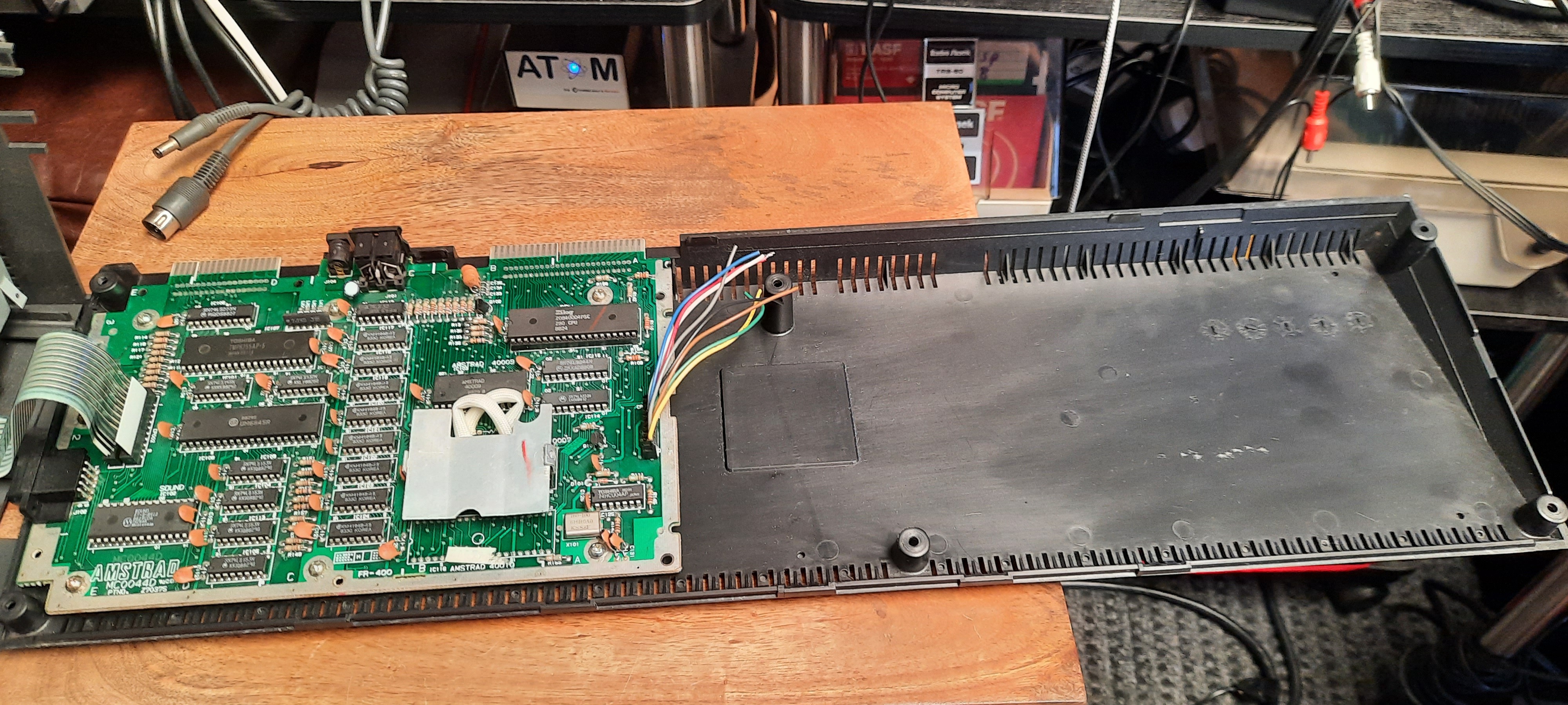
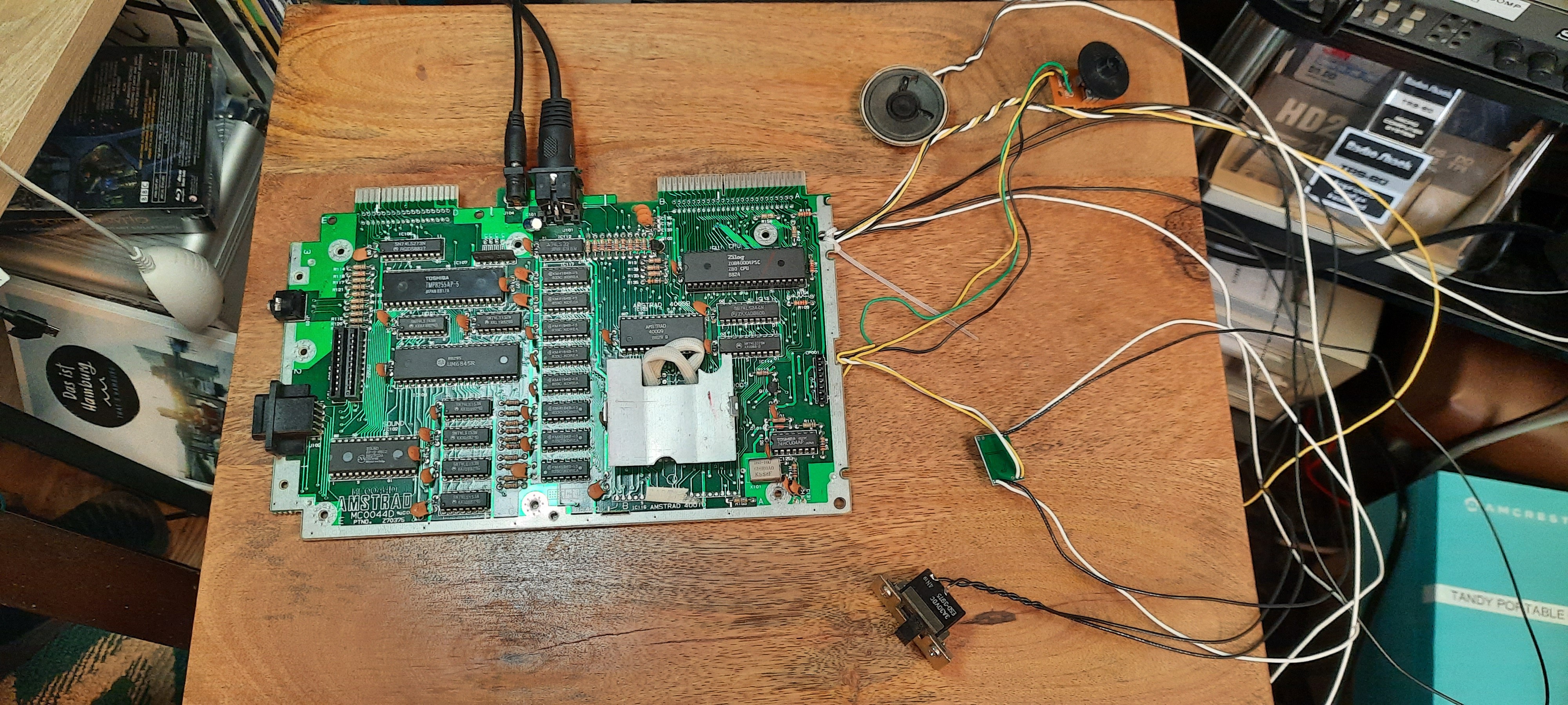
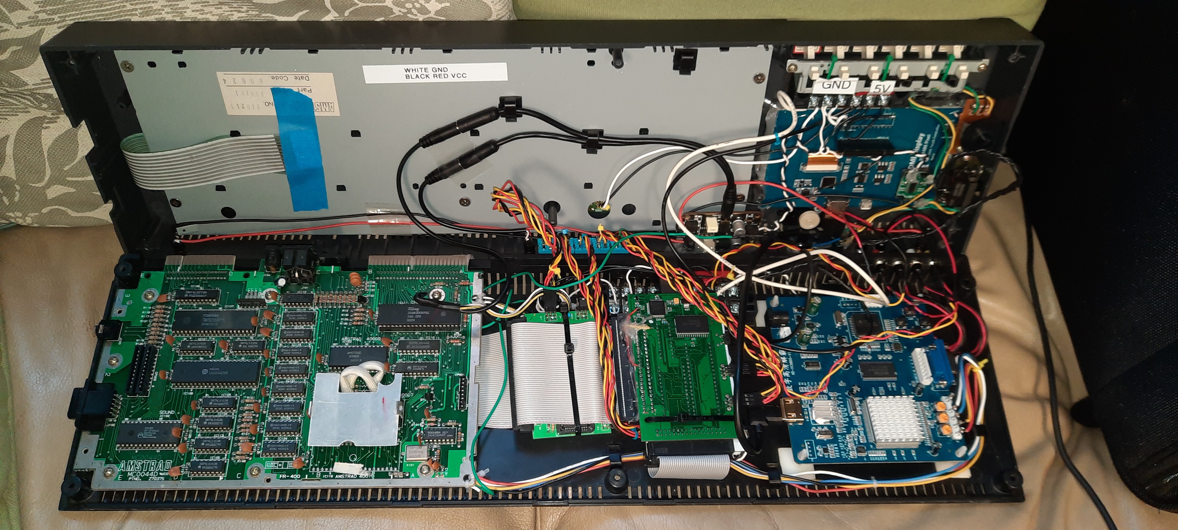
The CPC 464 which I acquired years ago and which was sitting unused in my storage bins has the much smaller cost-reduced MC0044D motherboard, leaving plenty of empty space in the case. What could this extra space be used for? For extensions, of course!
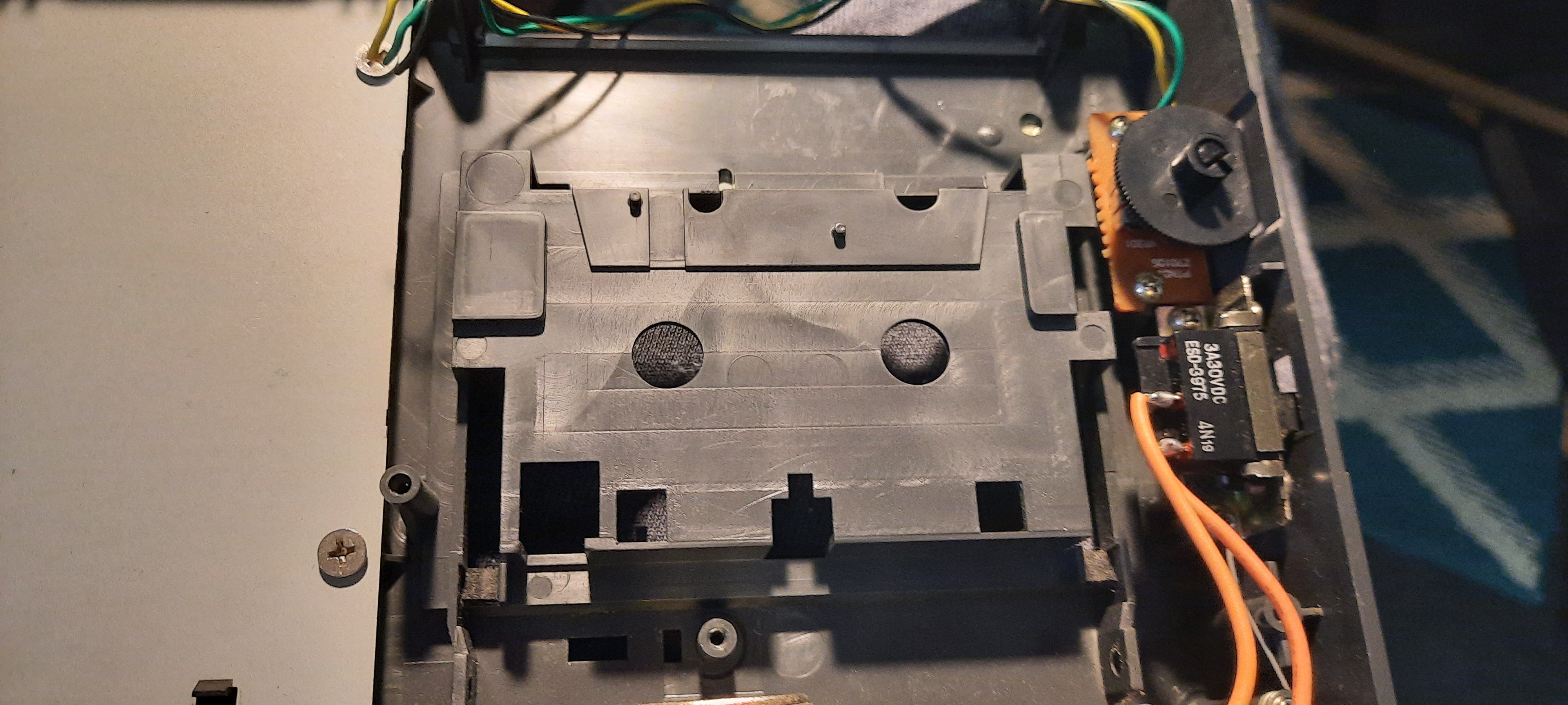
So, with the datacorder removed, I had some space to work with:
However, one caveat of a CPC 464 without datacorder is that you will have to rewire the main power switch, the power LED, the internal mono audio speaker which is driven by the datacorder's amplifier, and the volume pot as well. I hence had to restore these amenities using different means later.
Next, a suitable TFT display was selected. This was my first candidate which I picked based on required screen resolution (640 x 200 max for the CPC, so 800x480 should be fine), and screen dimensions (5" diagonal and promising looking aspect ratio). Would it fit?
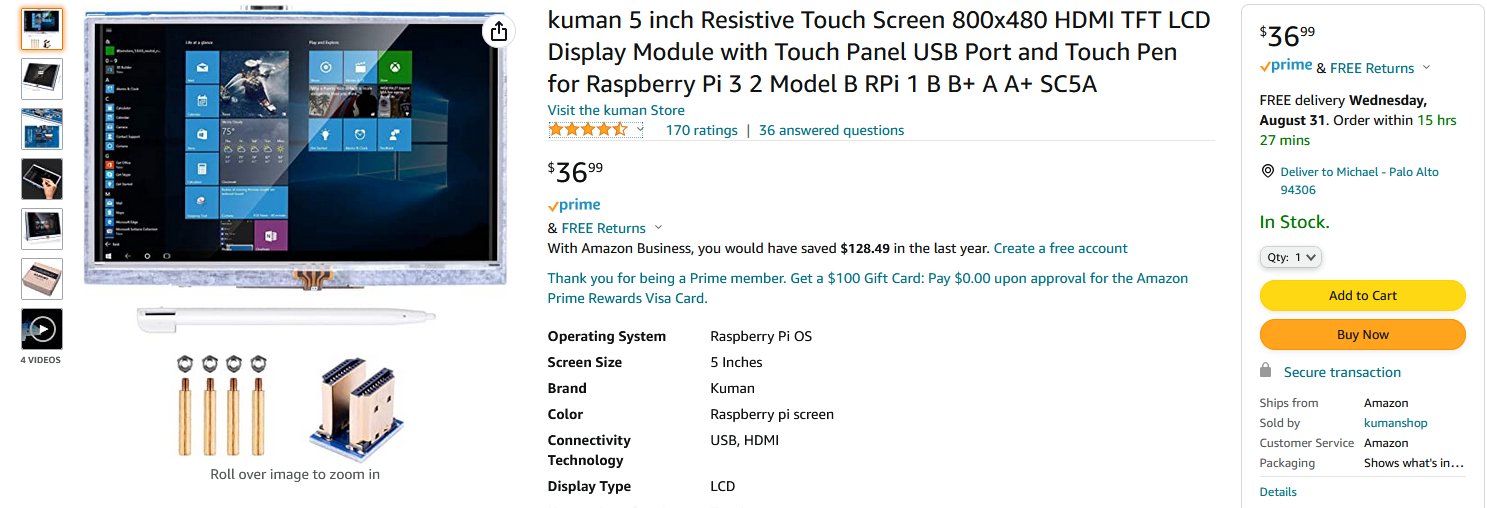
And indeed, it was almost a perfect match:
Given the position of the HDMI connector, the only option was to mount it from the inside of the case, such that it can be seen through the cassette player compartment. I thus acquired an inexpensive Dremel-like rotary tool and got to work, cutting out the cassette player compartment and supporting struts such that I could mount it flush:
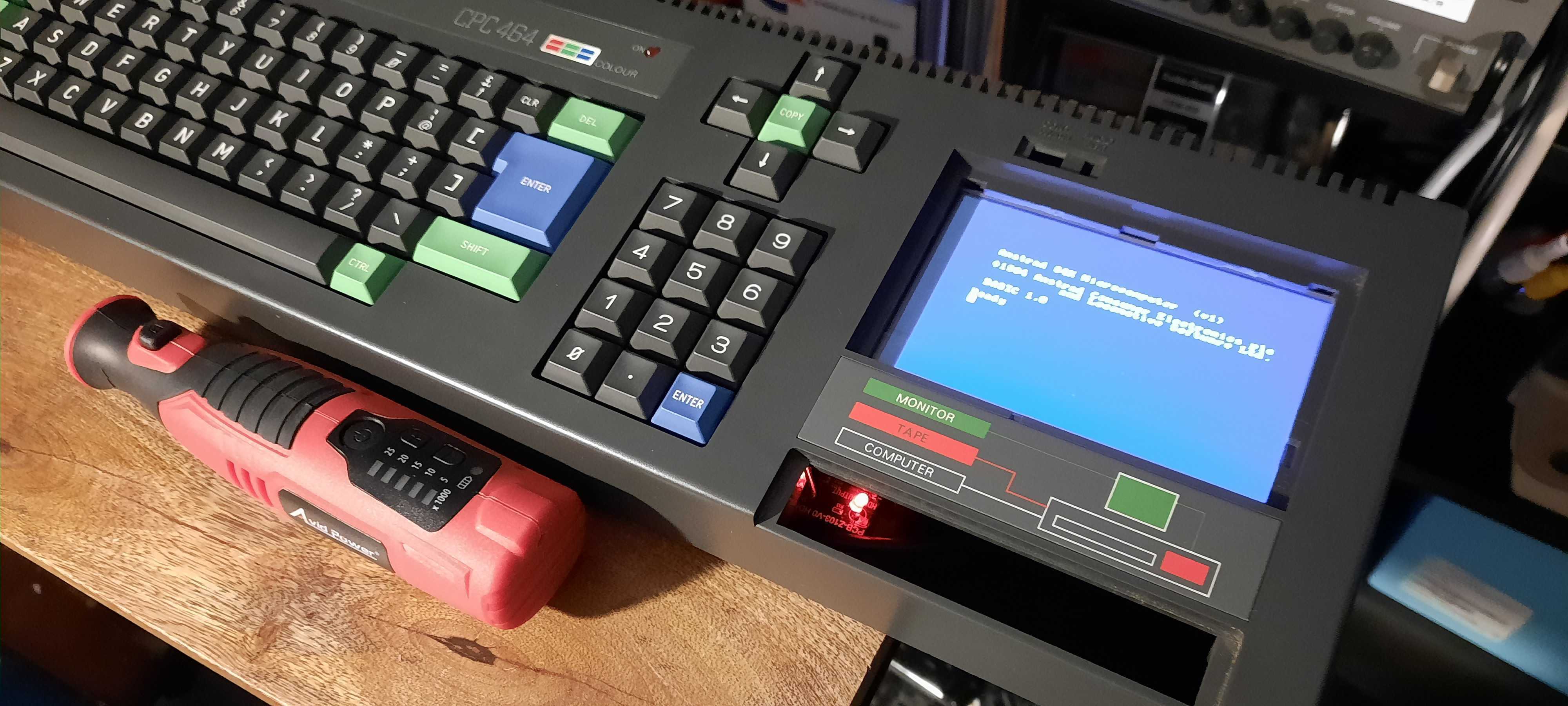
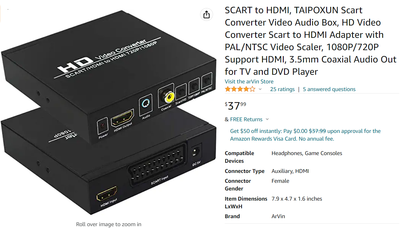
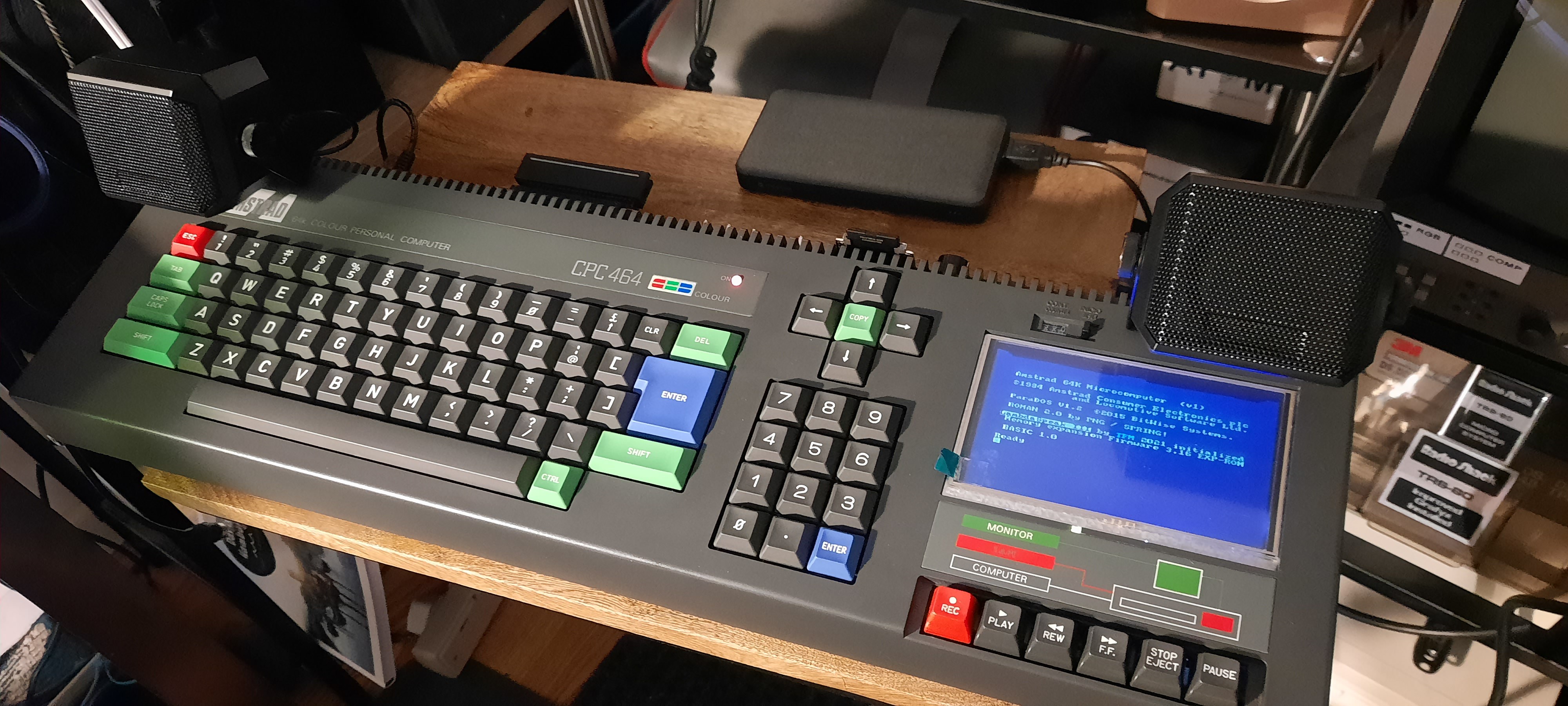
After a bit of cutting and sanding, I was then indeed able to mount the display from the inside. First only provisionally using clear tape to check if it works out at all - I then connected it to the CPC with my trusted SCART2HDMI converter, and voilà, the CPC had a display:
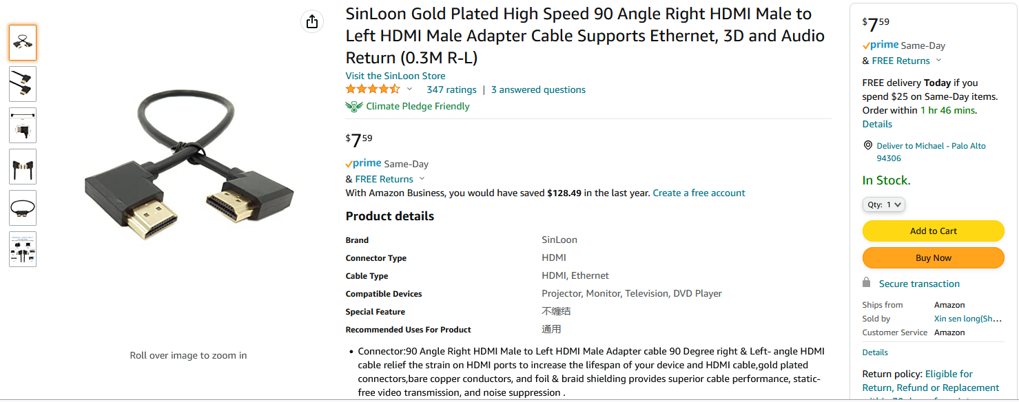
A short, slim-profile, right-angled HDMI is essential as well. I found a good candidate here:
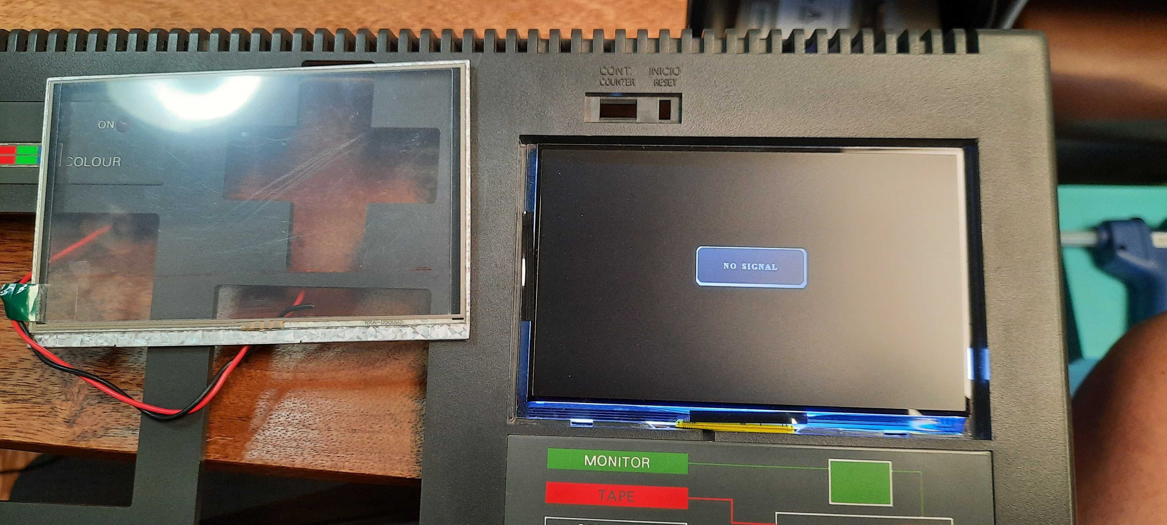
Unfortunately, I realized that the SCART2HDMI converter that I had been using for the last 5 years wasn't playing nicely with the little display: the 2 bottom text lines from the screen weren't visible. The picture geometry cannot be adjusted with this one:
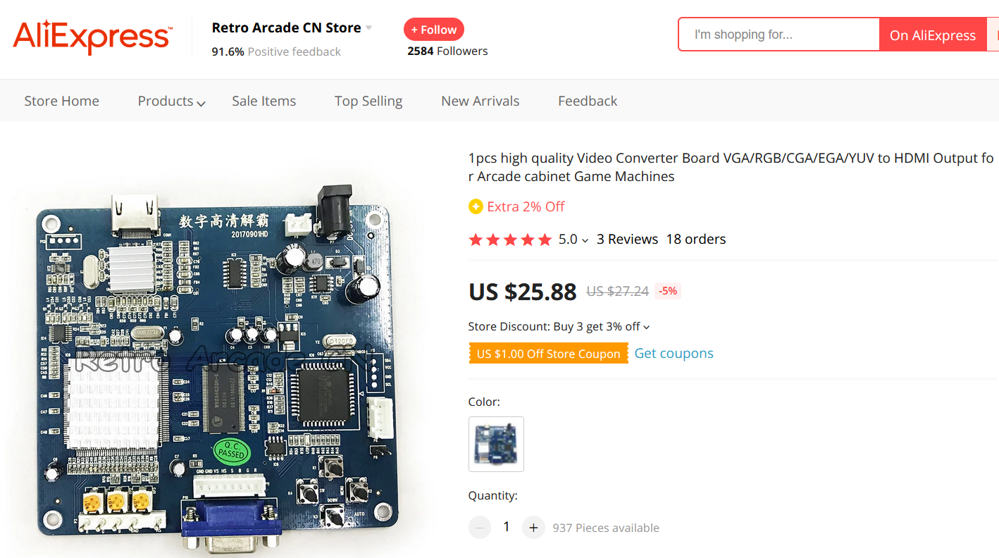
So I also needed to find an alternative converter. I found an interesting candidate on AliExpress, the HDMI-output version of the well-known GBS-8220 converter, and thought I should give it a try:
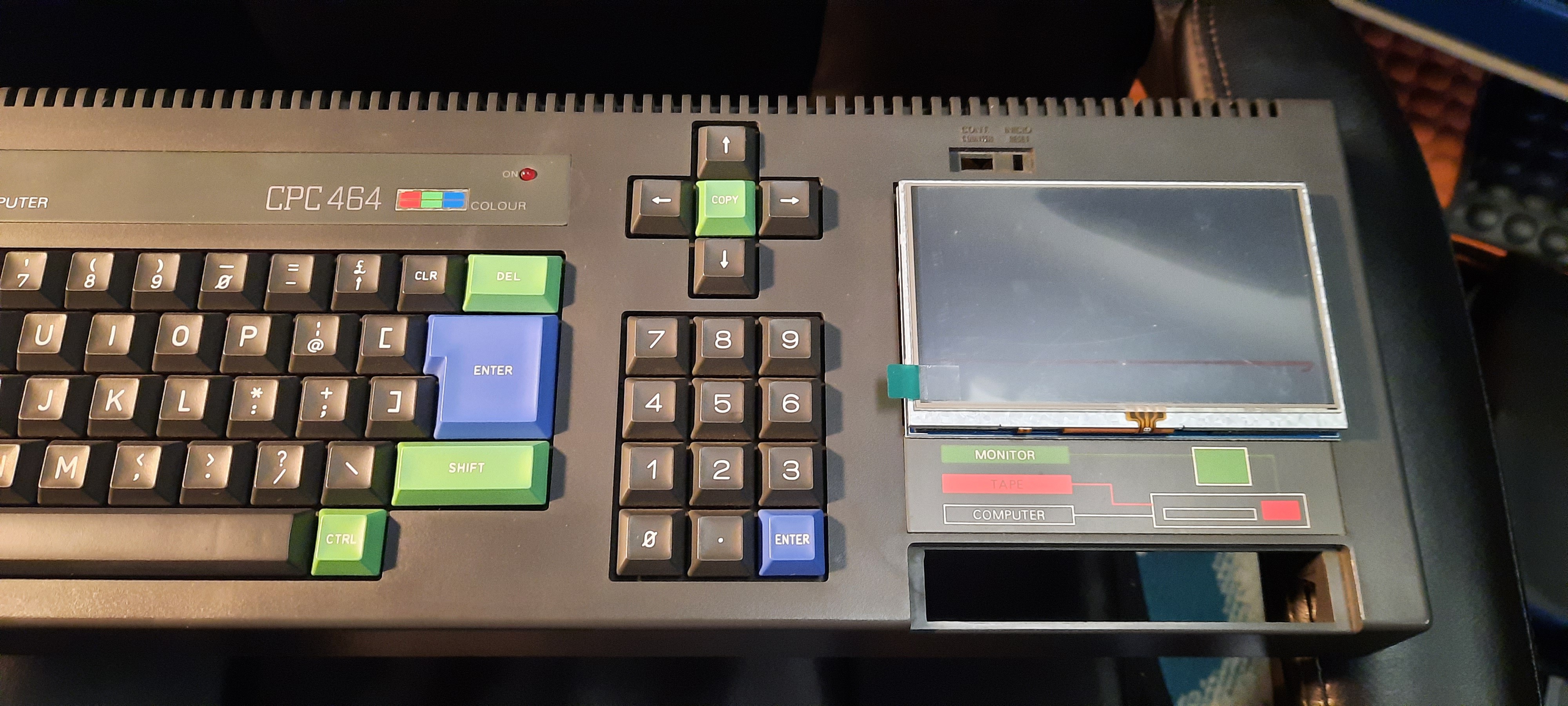
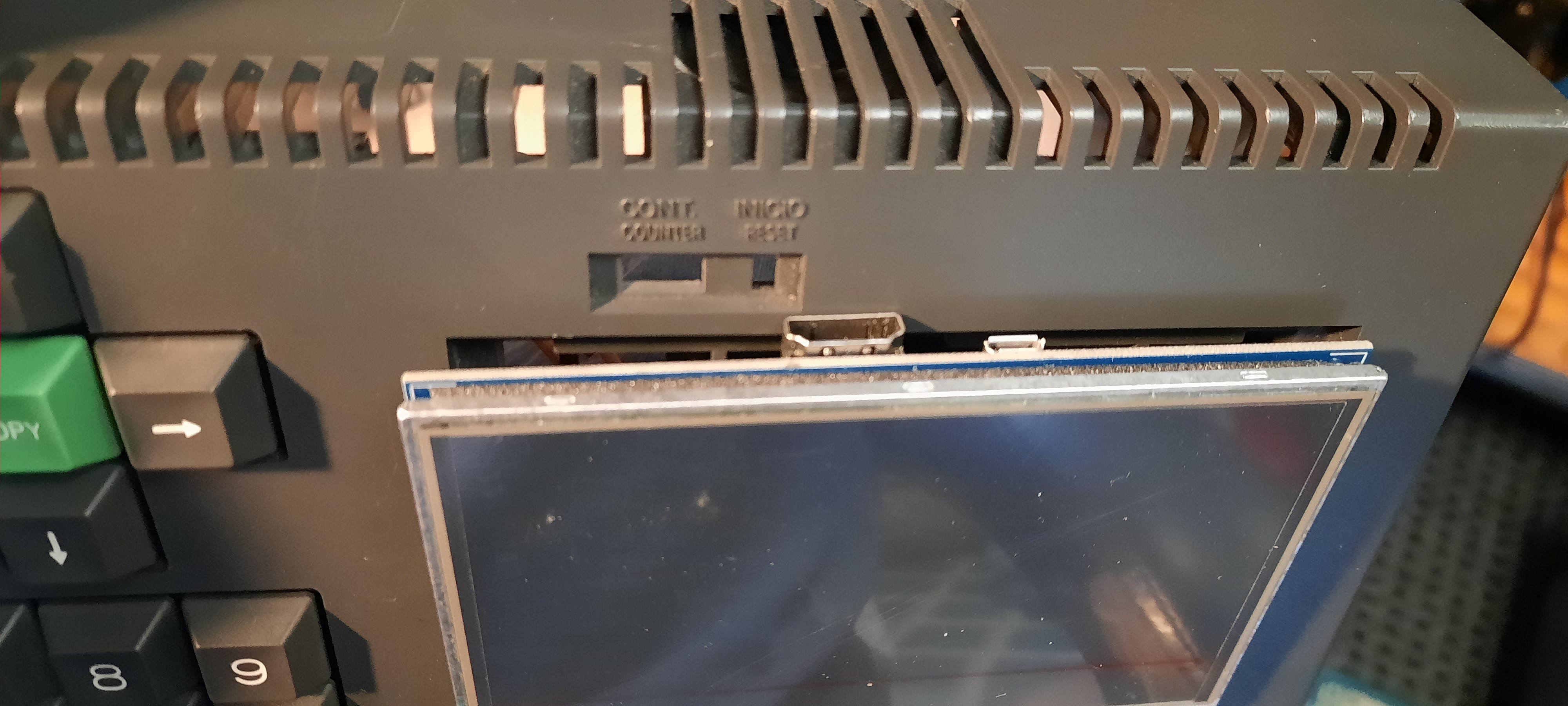
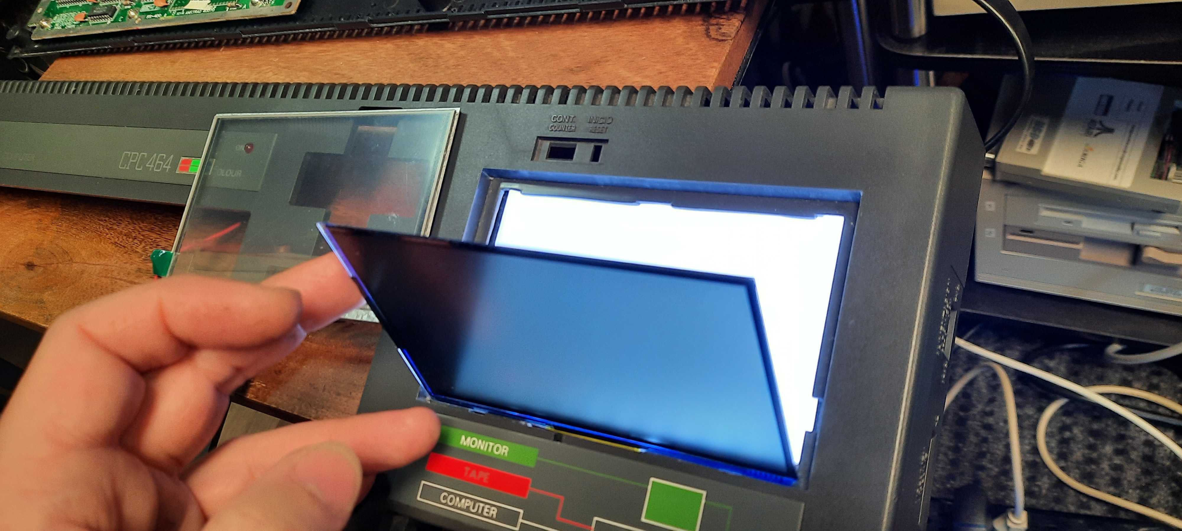
Moreover, I still wasn't happy with the display. Sitting recessed at the bottom of the datacorder compartment, It just didn't look right. I hence decided to be more daring and aggressive with my mods - what if I separated the display from the backlight PCB? I found that the metal bezel was only clamped on, sandwiching the touchscreen and display to the backlight PCB, and that it was indeed straightforward to remove the frame simply by bending up some metal clamps. I then cut off the flexcable to the touchscreen, and kept the other one which connects the TFT to the backlight PCB. I was then able to achieve a much cleaner look:
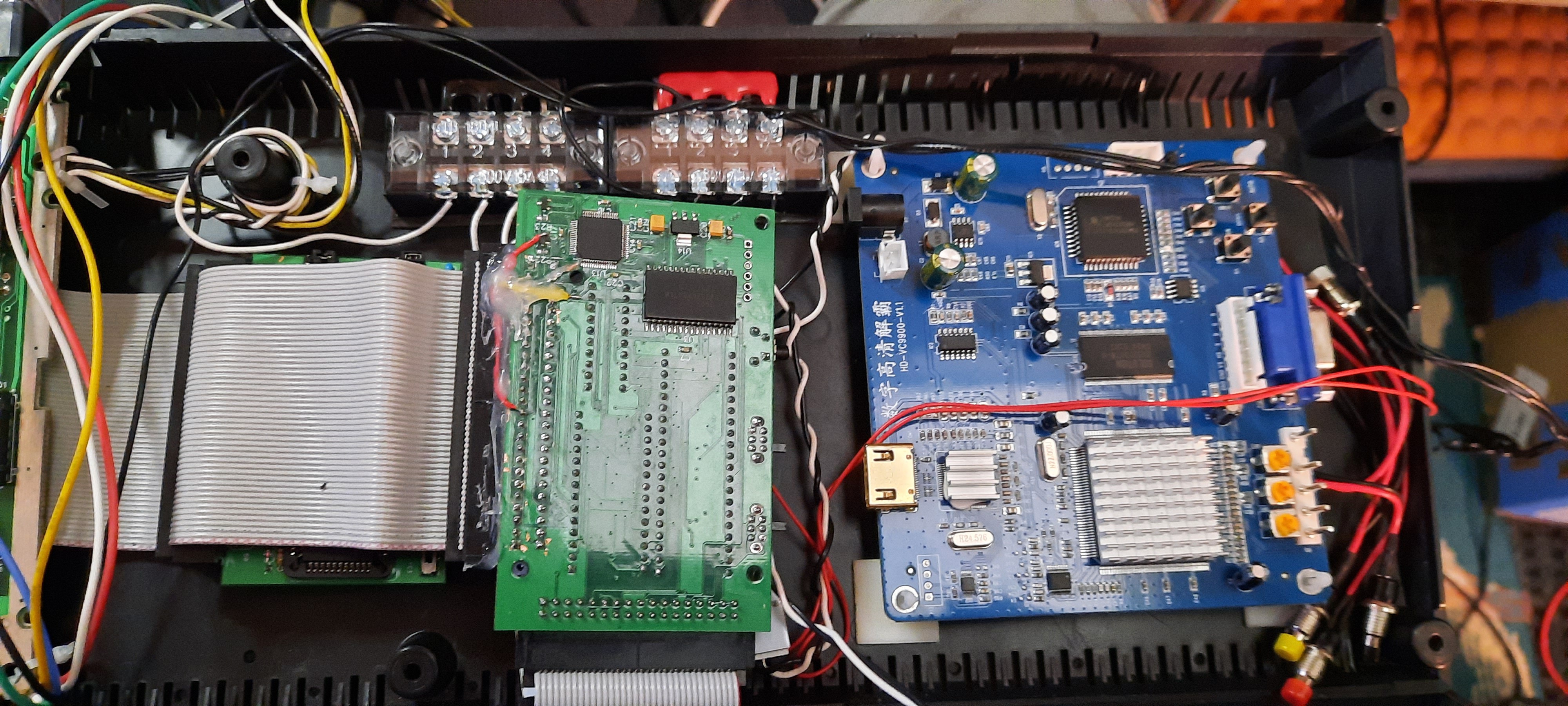
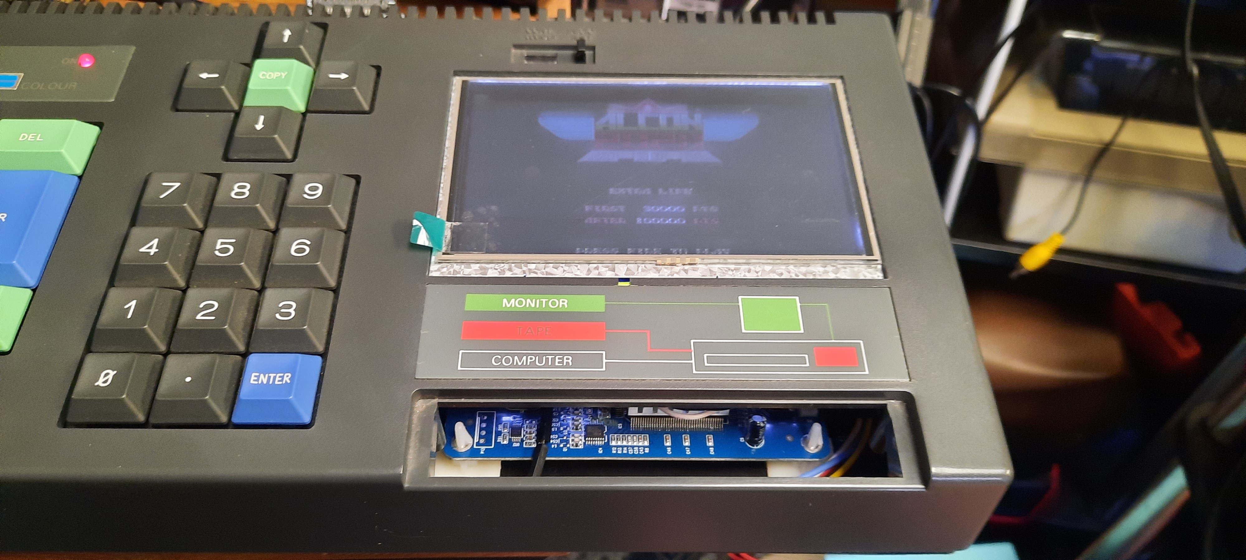
 The new converter arrived and testing confirmed that, unlike my previous SCART2HDMI converter, it gave me full geometry and color control! Yeah! And, being still sharp and clear at 80 chars per line, with no noticeable visual lag, allowing for direct RGB-S input (better than Scart indeed!), it is the perfect converter for the CPC! After cutting off 2mm of aluminum from the right edge of the metal bezel with my rotary tool, I was then able to make it fit inside the datacorder compartment perfectly, protecting the precious display (well, precious in terms of invested labor hours, not $'s):
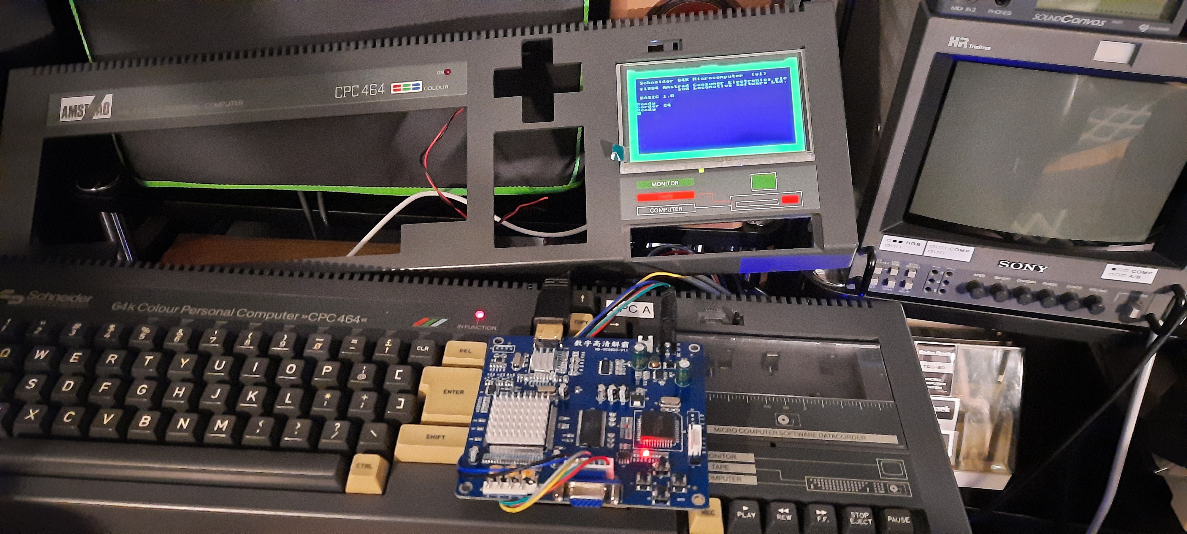
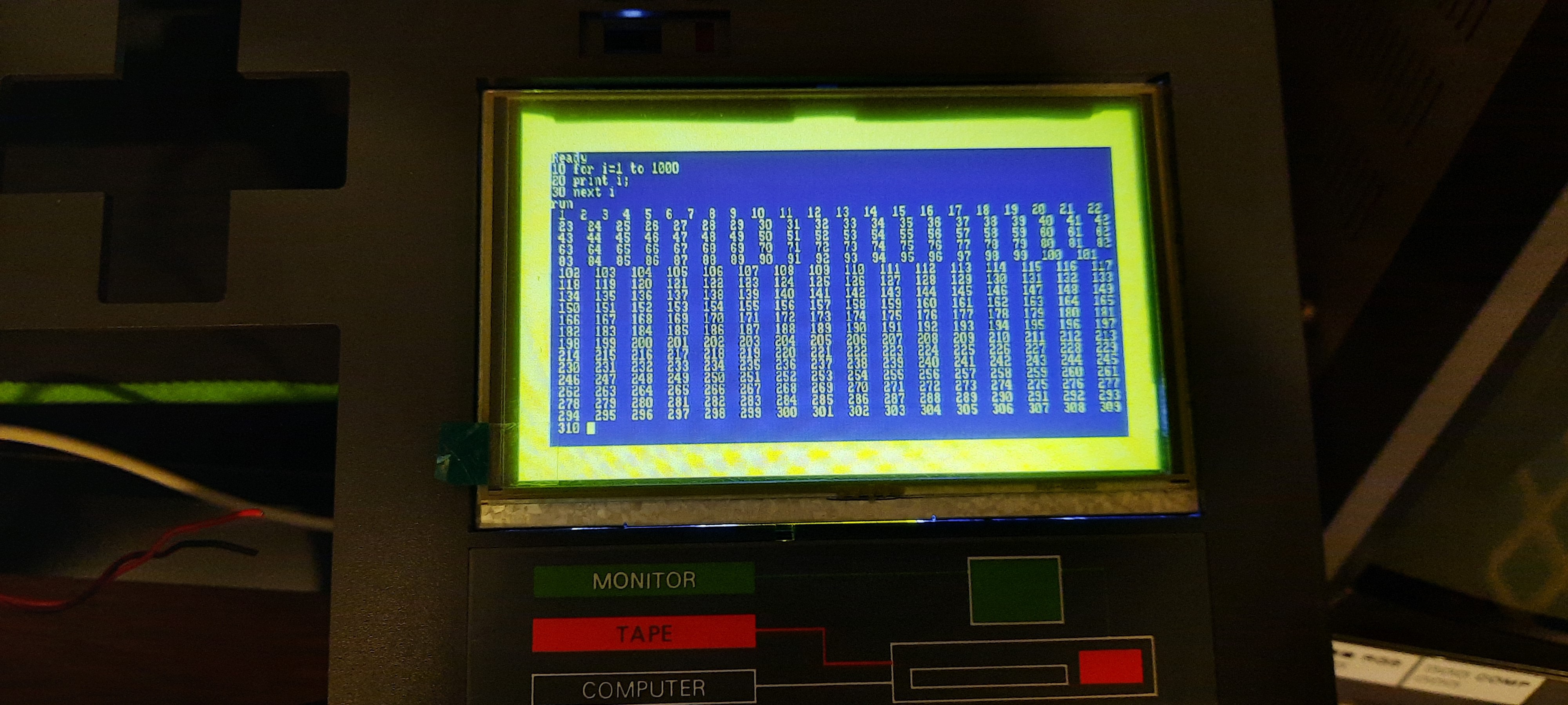
With the video system sorted, I then turned my attention to the extension cards. These days, CPC extension cards used the "MX4 standard", which is simply the 50pin expansion port connector put on an IDC box header such that cards can plug into an expansion backplane. One of my first CPC PCB projects was actually to design such an "MX4 compatible" backplane extender myself: https://github.com/lambdamikel/LambdaBoard
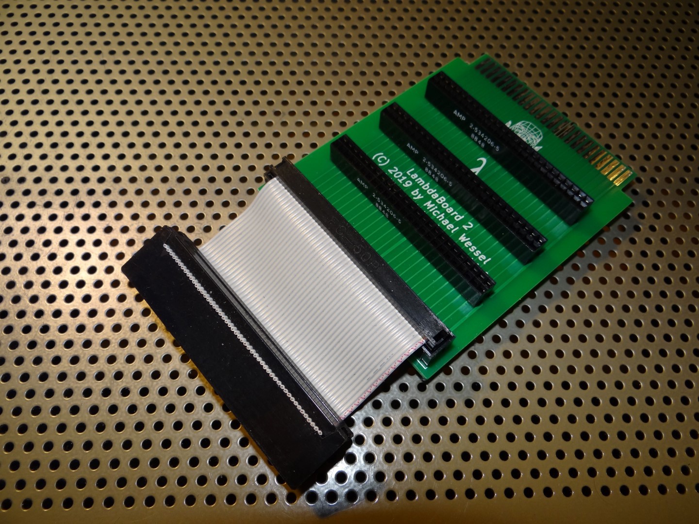
However, there is obviously no space for cards standing upright in the CPC case, so I needed a different solution that would allow them to lie "flat". I hence did the next best thing - and simply put the cards on a ribbon wire. Initial tests confirmed that this 50pin (SCSI-like) "cable bus" was still working reliably with 3 expansion cards, and no additional bus drivers were needed:
In order to still be able to mount at least one additional external extension card, I was relying on another old project of mine: https://github.com/lambdamikel/CPCConnector
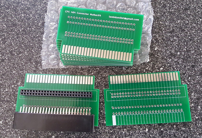
Plugged into the back of the CPC expansion port, it allows to mount one MX4-compatible extension card, and thanks to the edge connector passthrough, the cable bus can go back into the CPC to the internal extensions then.
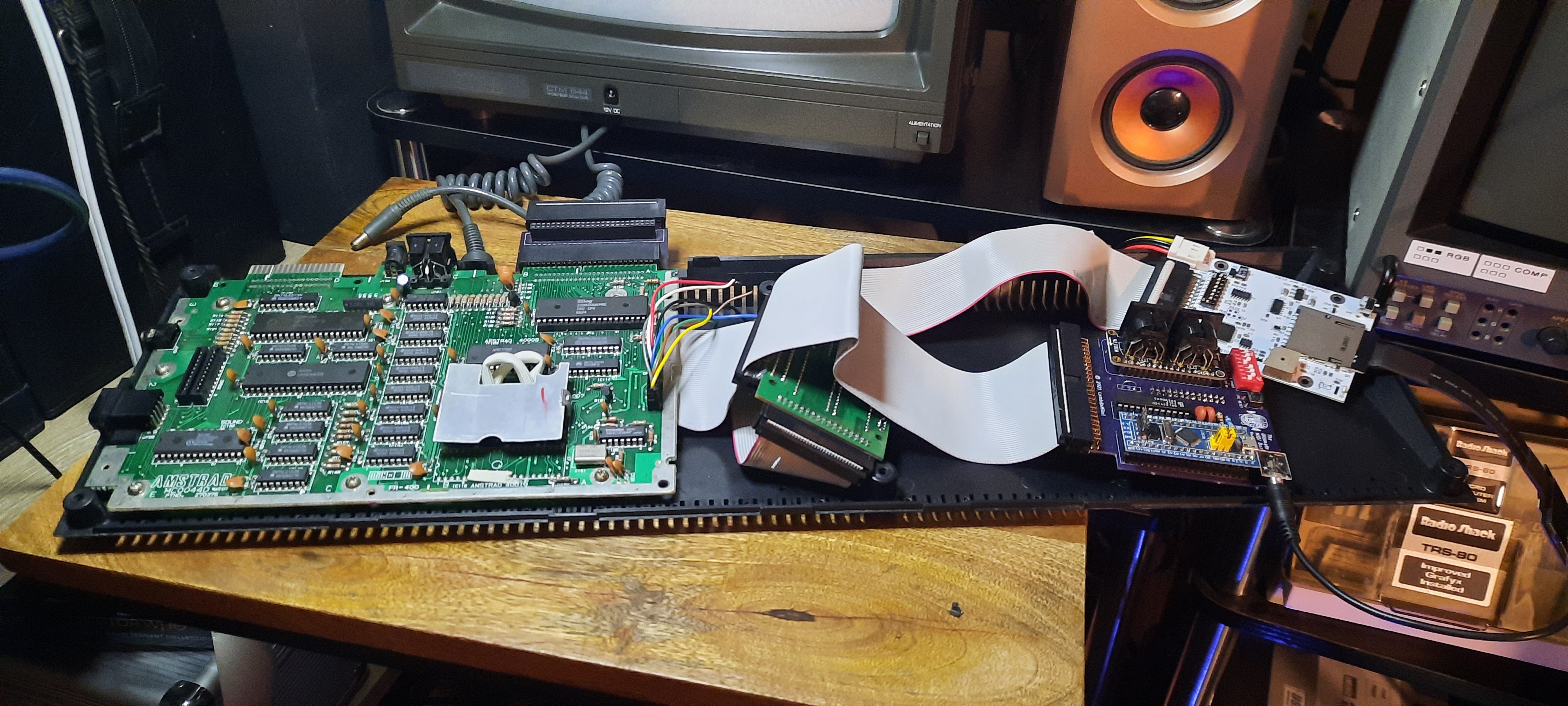
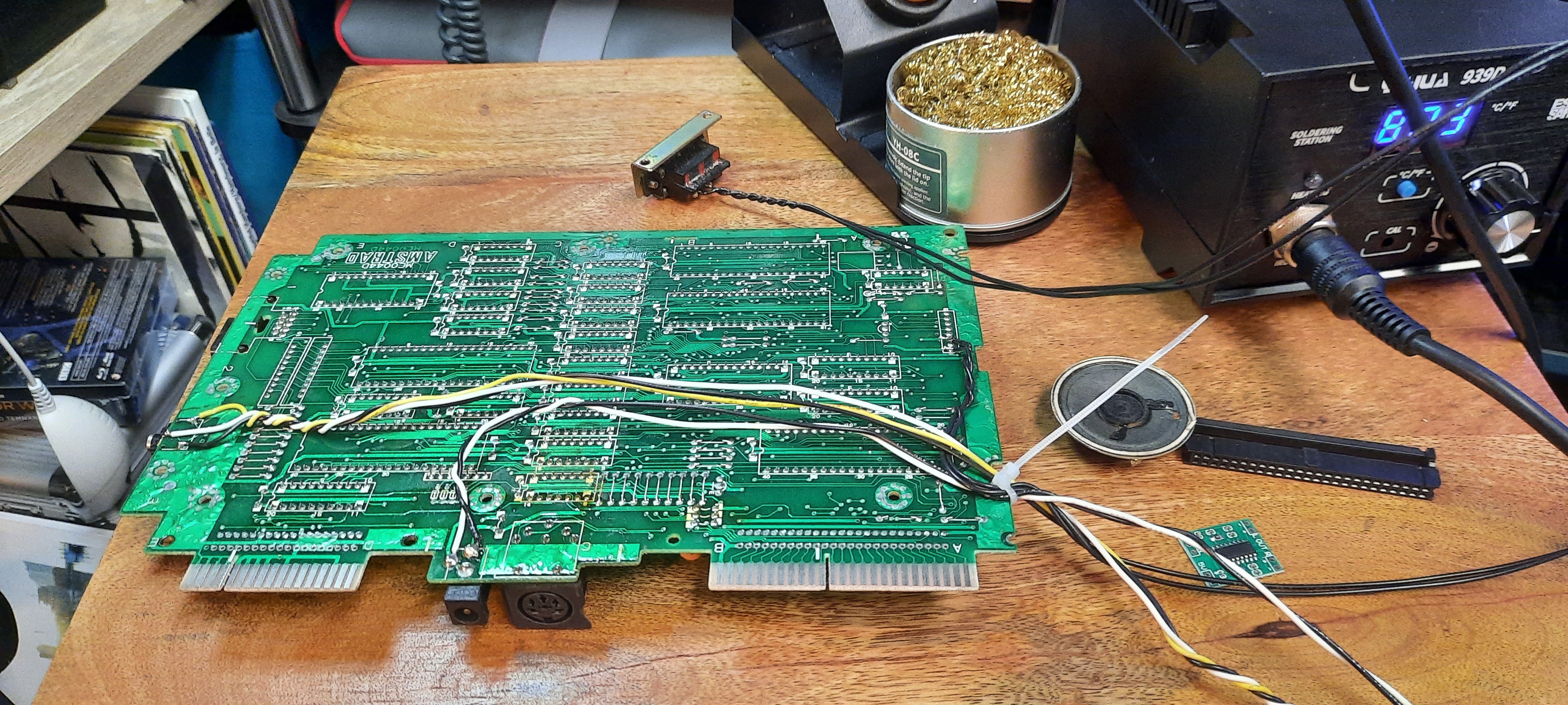
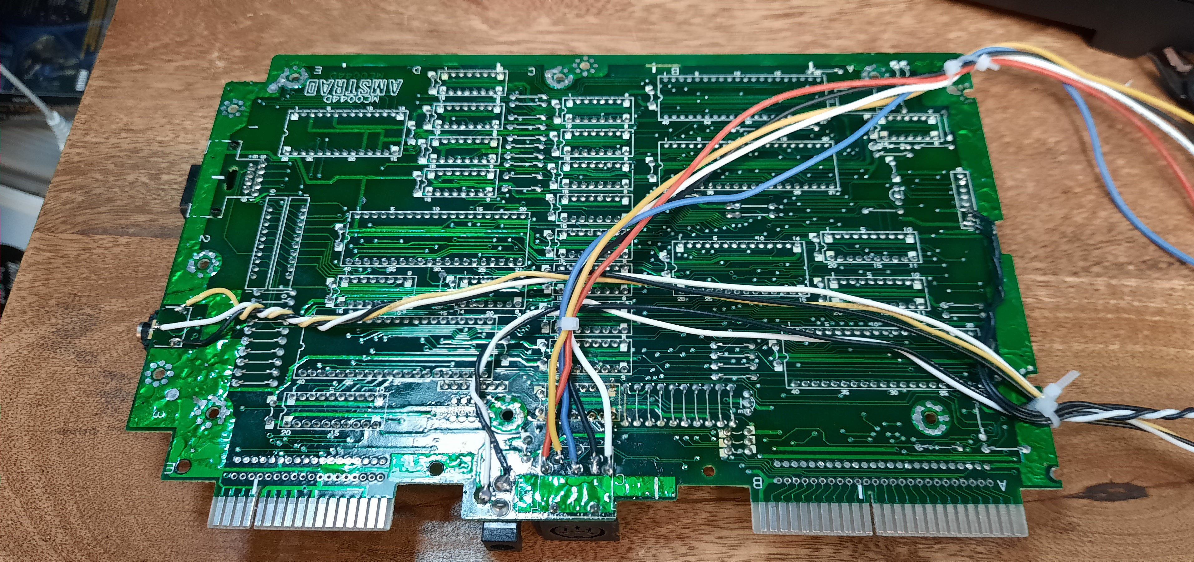
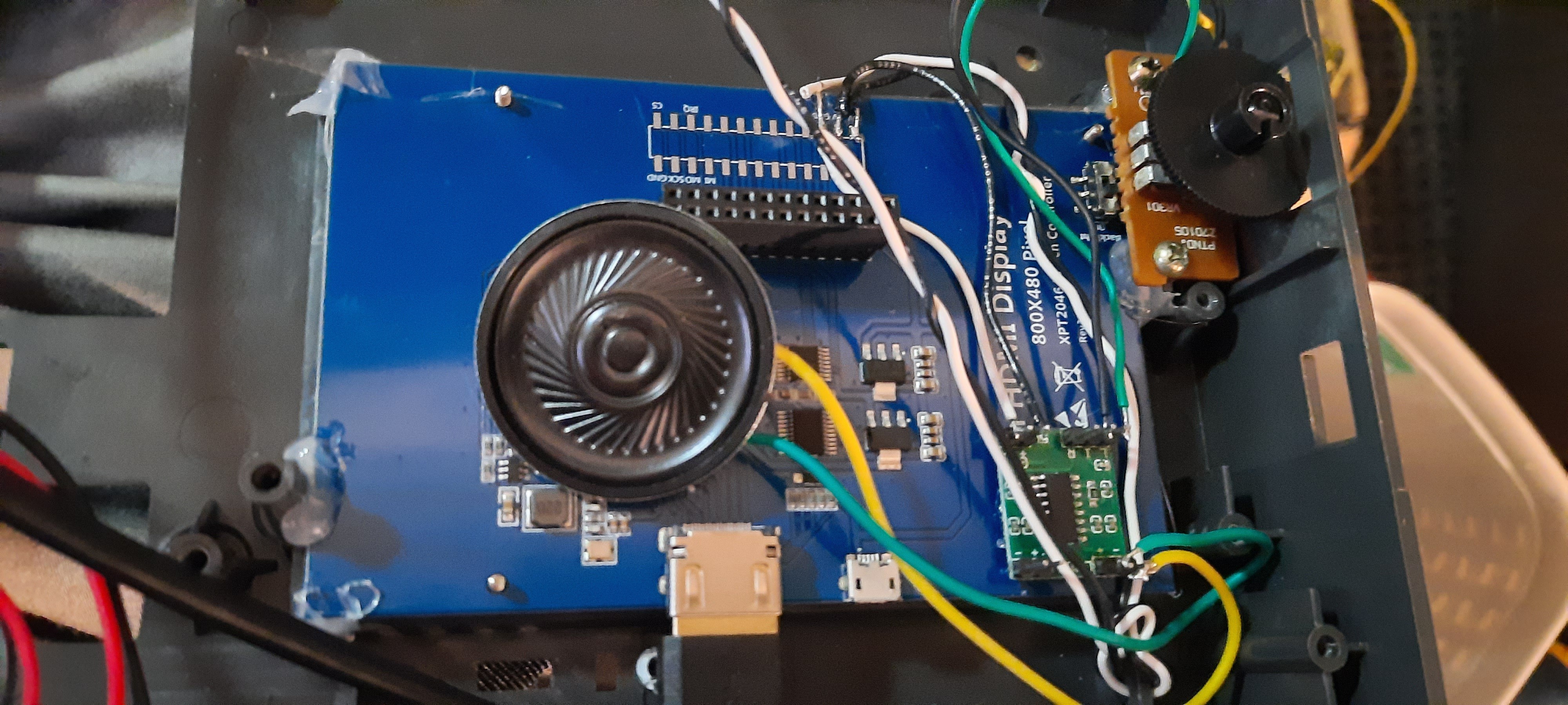
With the extension card issue sorted, it was then time to work on the motherboard! So I started to solder wires to the motherboard so that I could grab stereo audio, mono audio, power supply, and RGBS video output from the board:
In order to restore mono audio for the internal CPC speaker, I chose a PAM8304 2$ audio amplifier board, which is perfect for this use case (it runs on 5V and actually sounds better than the original amp in the datacorder):
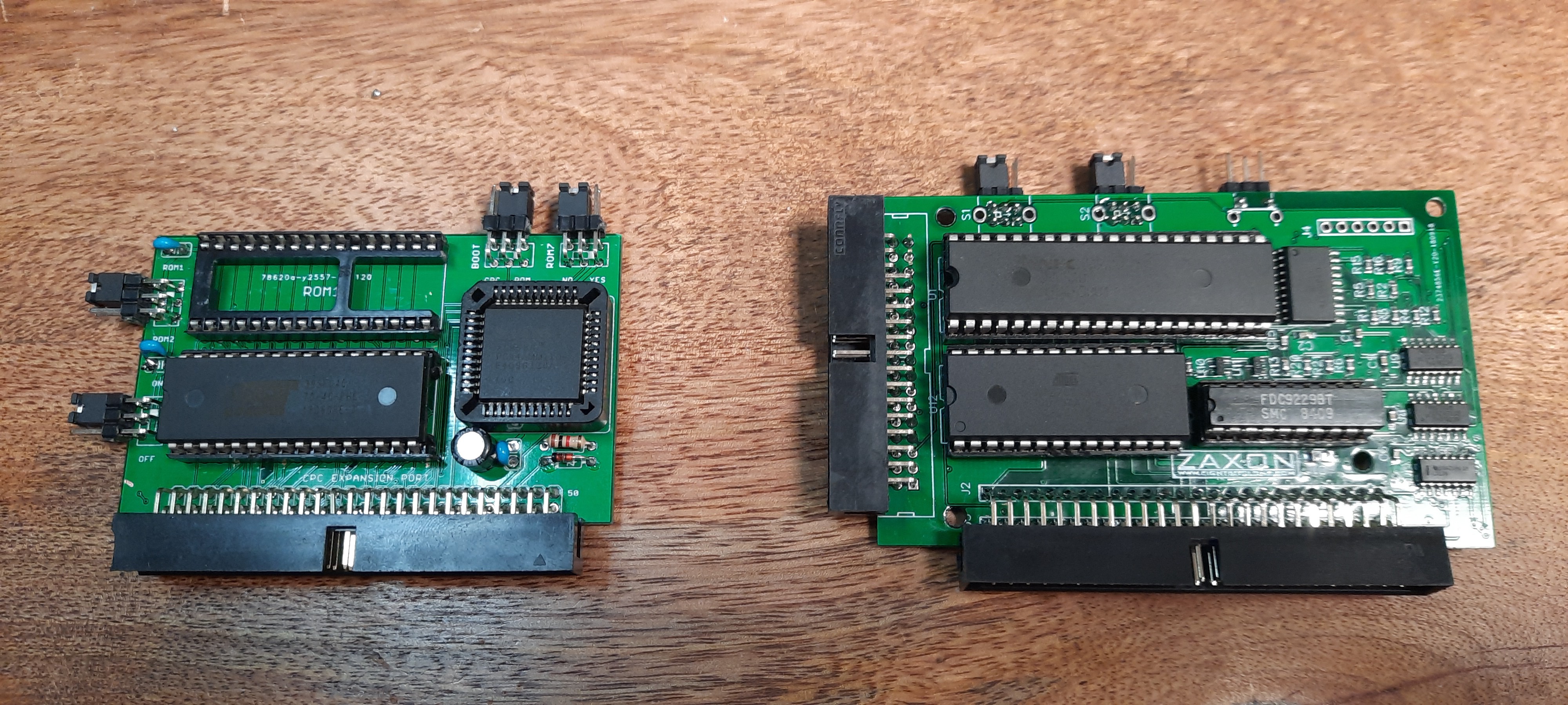
What extension cards would I need? Well, obviously a disk controller... the CPC 464 doesn't have one built-in. A few years ago I had purchased Zaxon's DDI4 disk interface, which even includes 512 KB of RAM expansion. It required some repairs and mods as well (originally it came with an edge connector, but now I needed a male IDC box header to connect it to the cable bus). For the floppy drive, I selected the SD S - HXC SLIM from Lotharek: https://lotharek.pl/productdetail.php?id=38 It doesn't have a display and only one button for disk change - perfect! All the buttons and switches from the DDI4 need to be available from the outside, so I replaced the 3position config switches with pin headers.
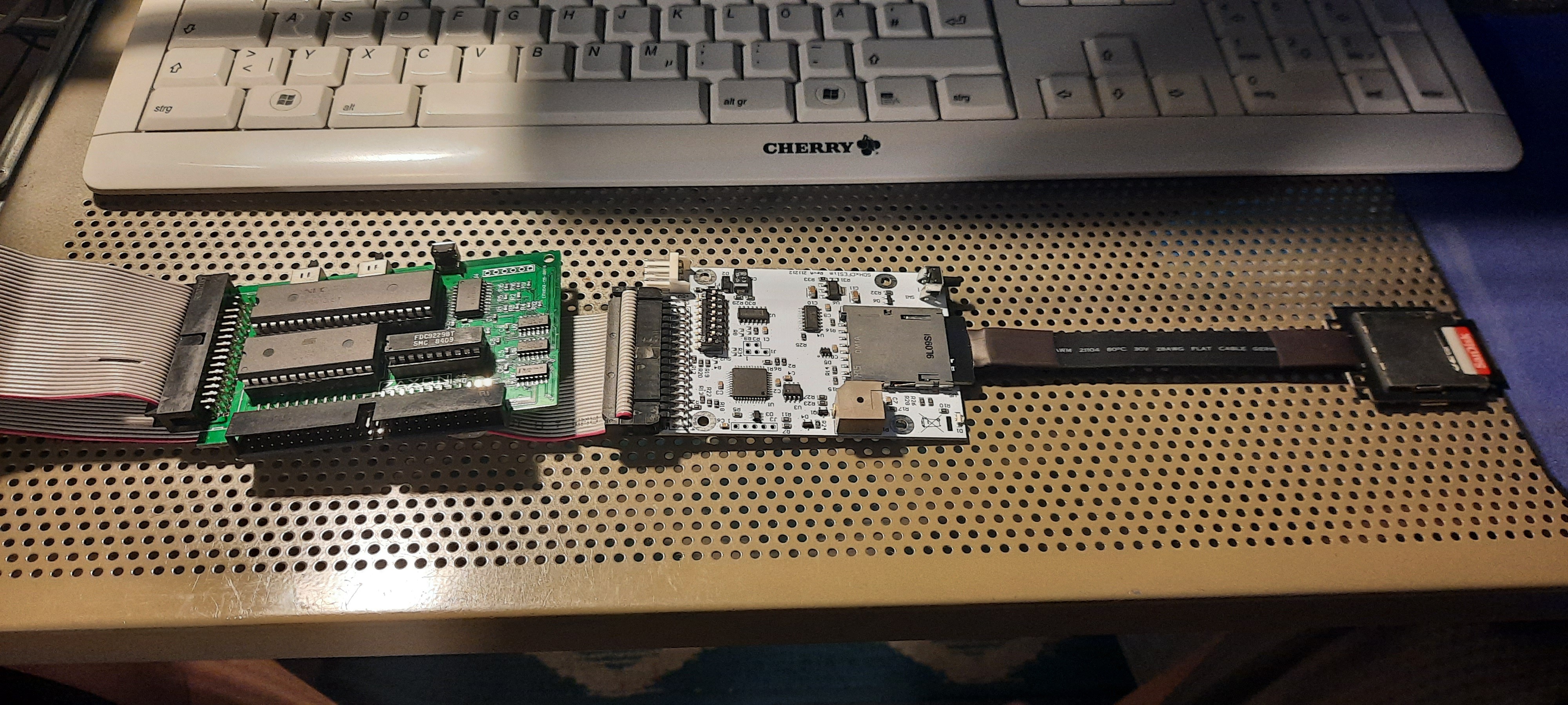
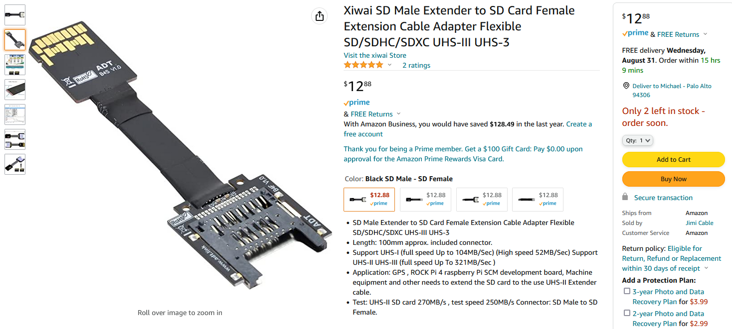
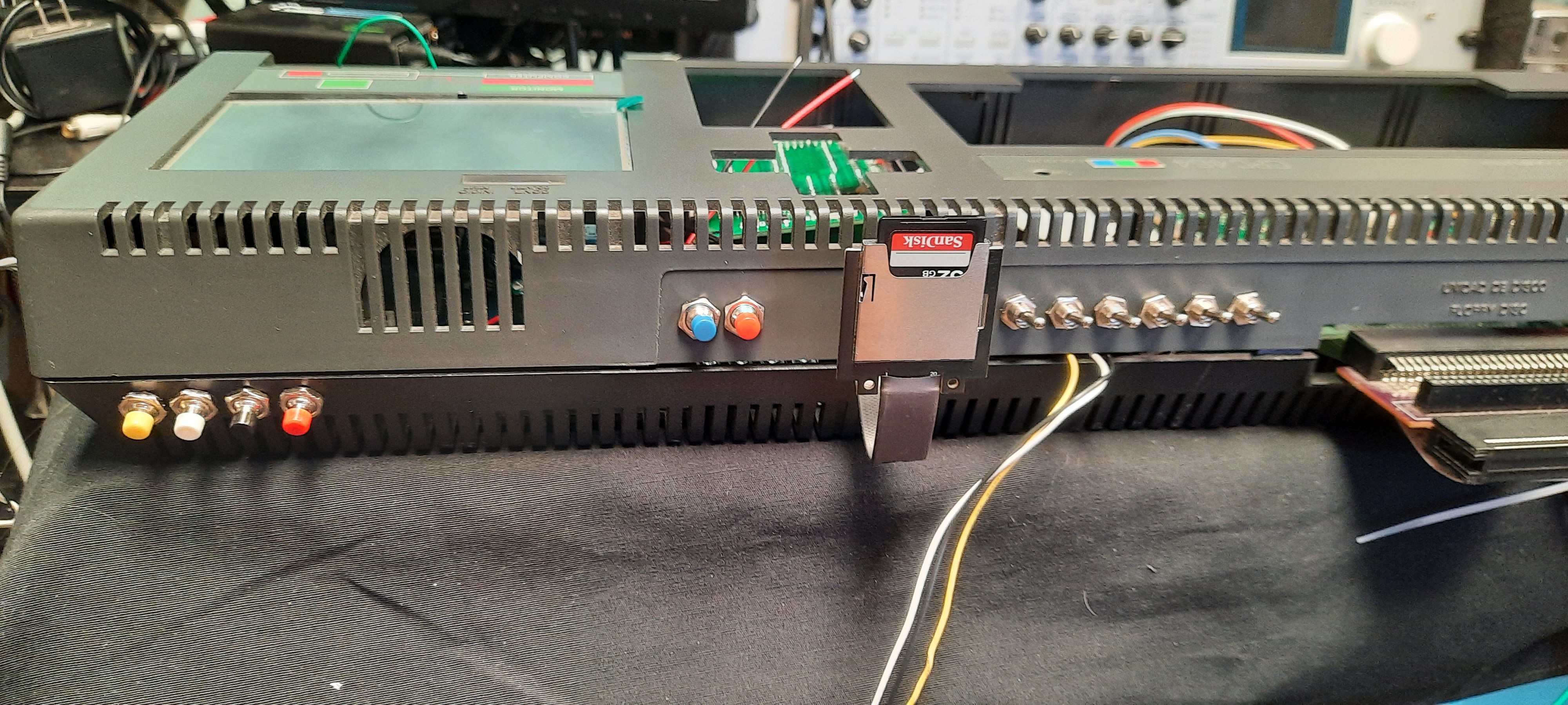
To gain access to the SD Card from the outside, this extender was selected:
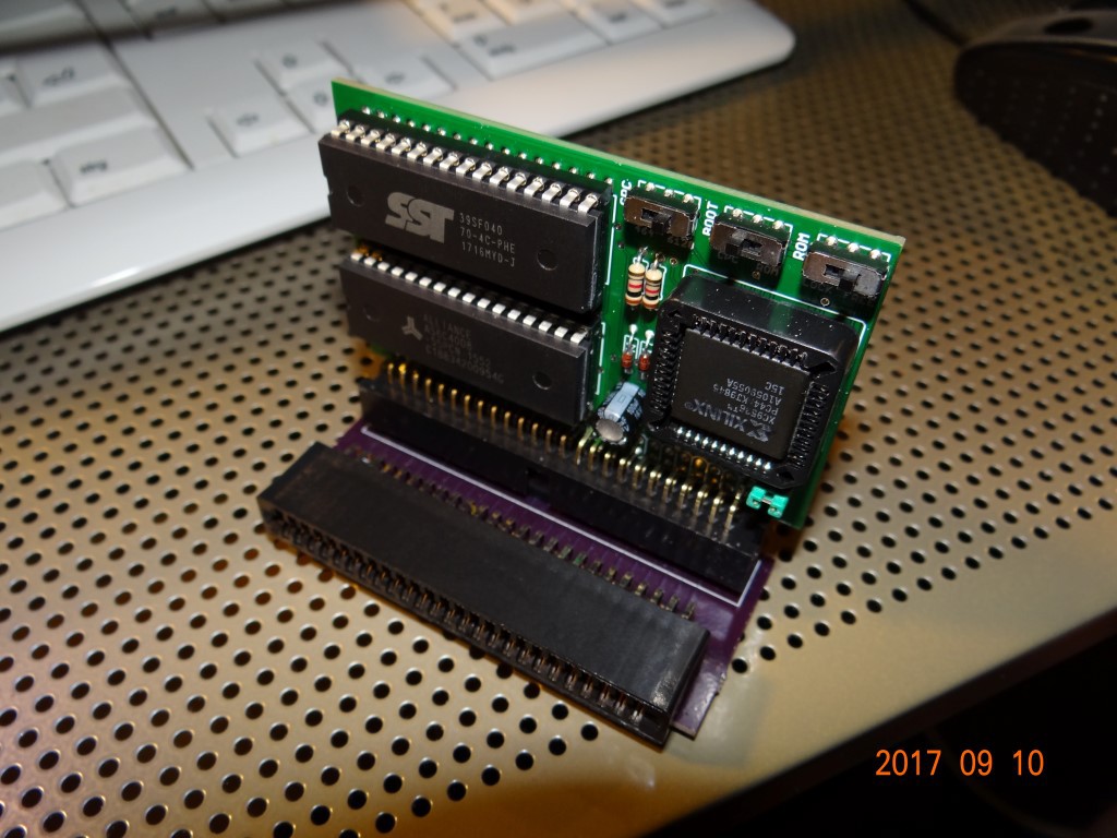
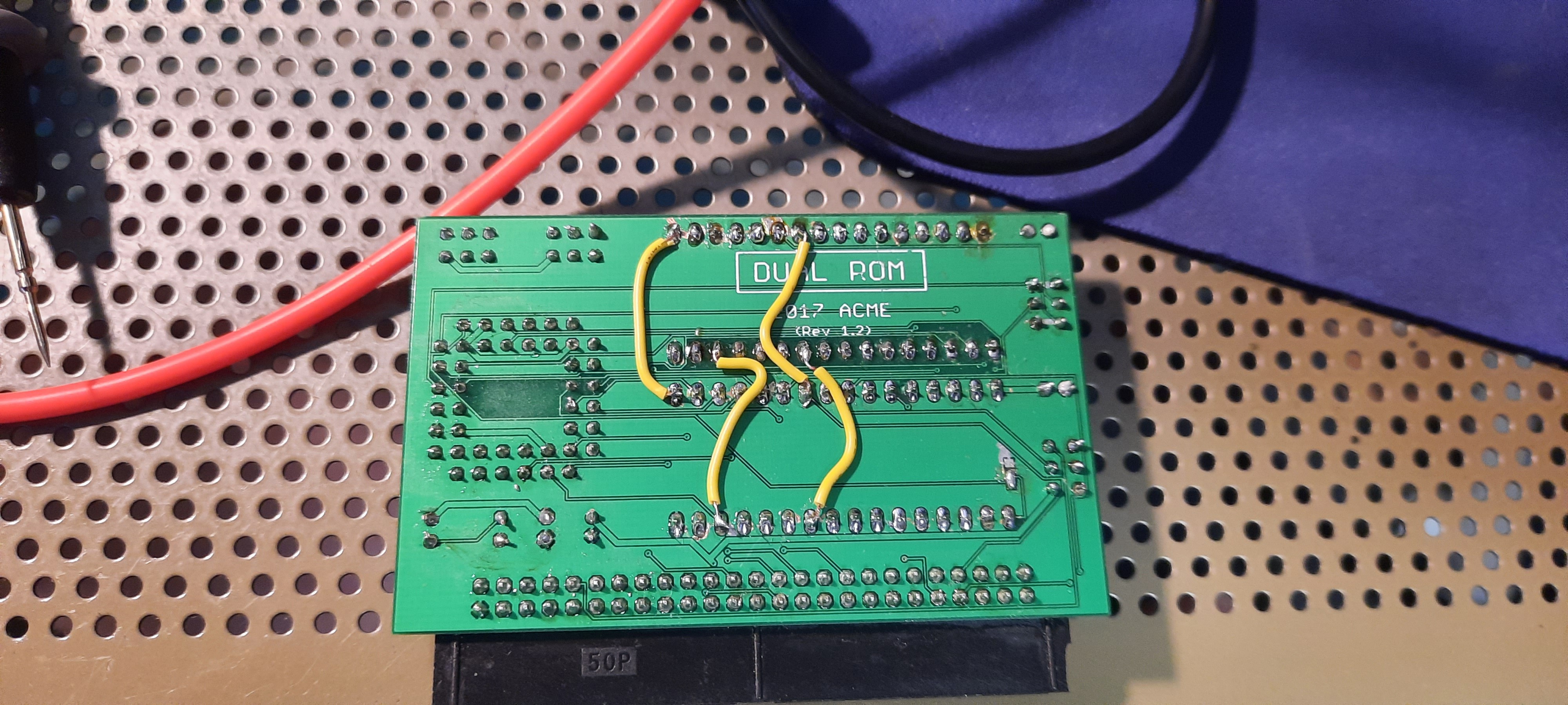
The next extension board that I selected was the D-MEM from Richard Gatineau, also known as ToTO in the CPC-Scene. D-MEM offers Flash-based ROMs for the CPC. My D-MEM never worked, and I never took the time to figure out why, so it was sitting unused in my drawer for years. But with the right use case & motivation at hand, and with Richard's help (thank you!), we were finally able to fix it:
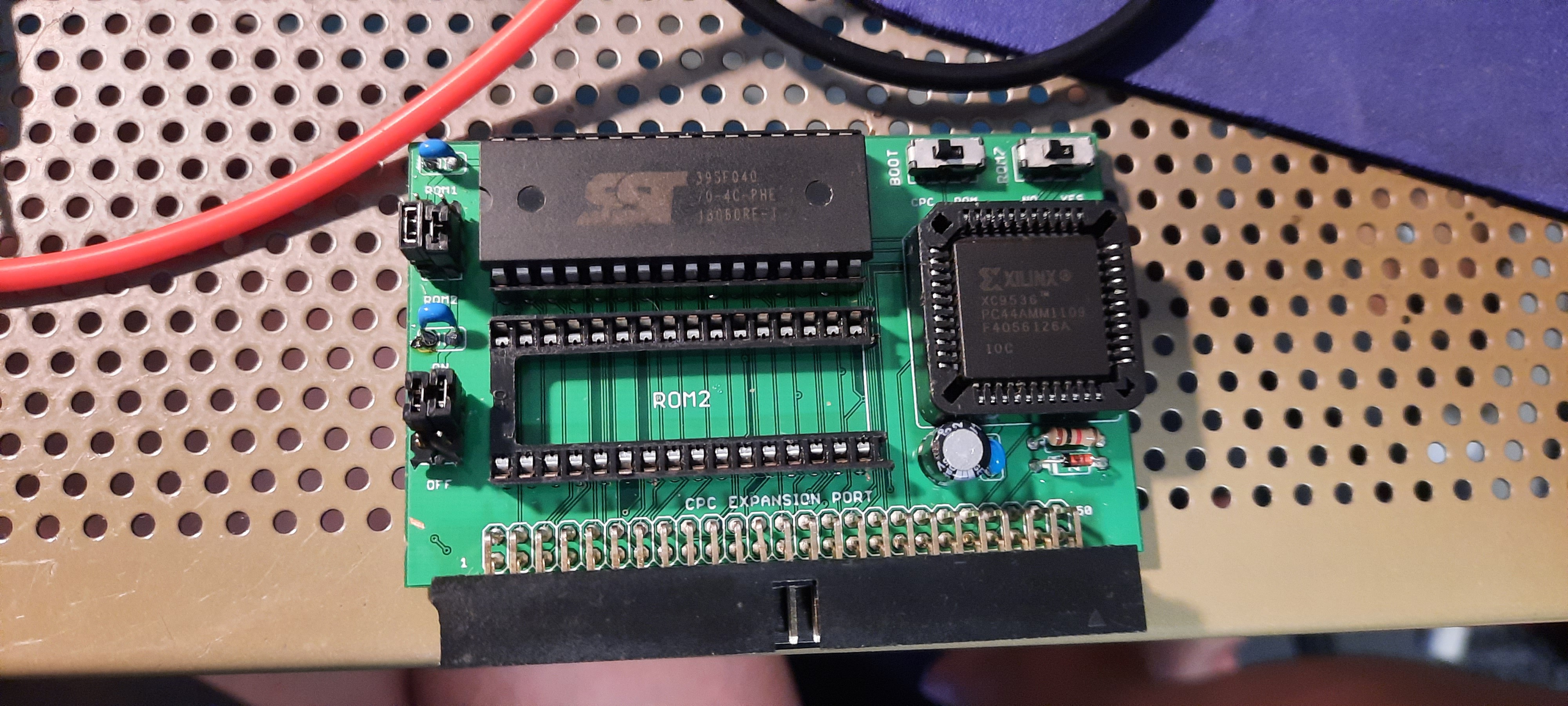
Fixing it required some bodge wires; apparently, some PCB traces were broken. I also replaced the two original 256 KB SST EEPROM flash chips with a single 512 KB one - ready to rock:
Both the DDI4 and D-MEM got pin headers (temporary jumpers in the picture) instead of their original switches and buttons such that they can be connected to the outside world via external buttons and switches:
The RGB2HDMI converter contributed 4 more push buttons as well:
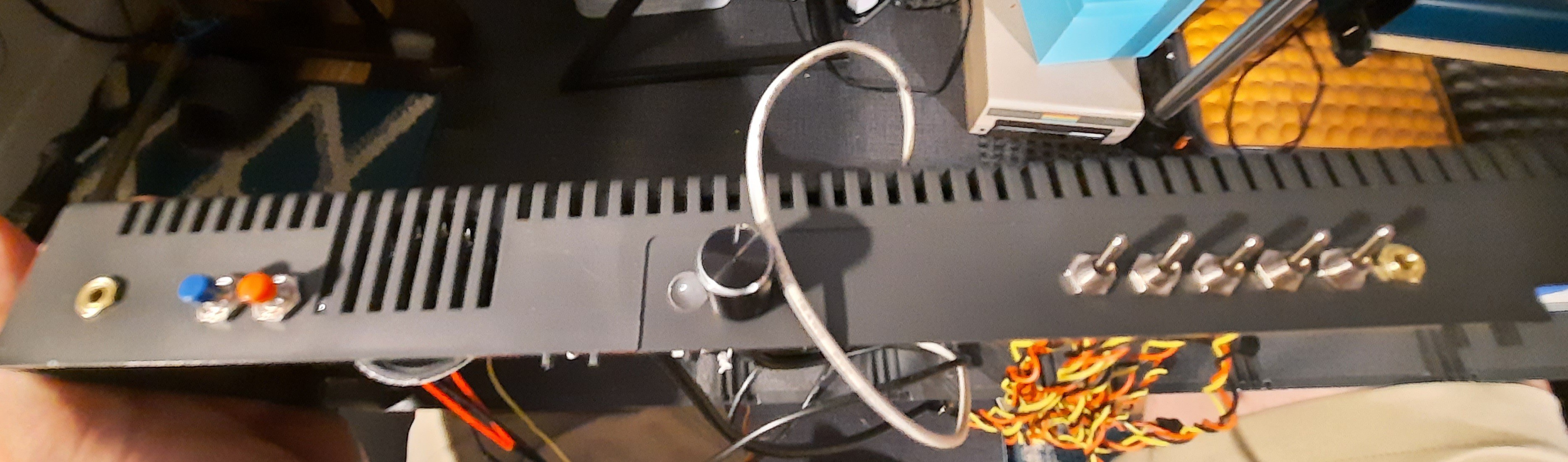
A number of (2x3 row) configuration switches and NOS buttons later, the CPC case looks like this - also note the MX4 slot and cable bus going back into the case to the internal extensions. From left to right, we have the 4 buttons for the converter, then HxC DISK CHANGE, CPC RESET, followed by DDI4 A/B drive and DOS (Amsdos / Parados) selector, then followed by D-MEM Boot ROM on/off, D-MEM ROM 7 on/off, and finally D-MEM on/off:
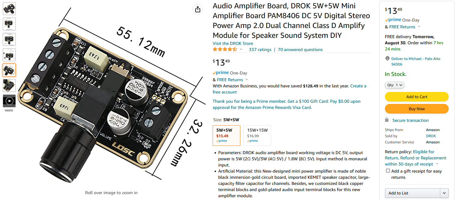
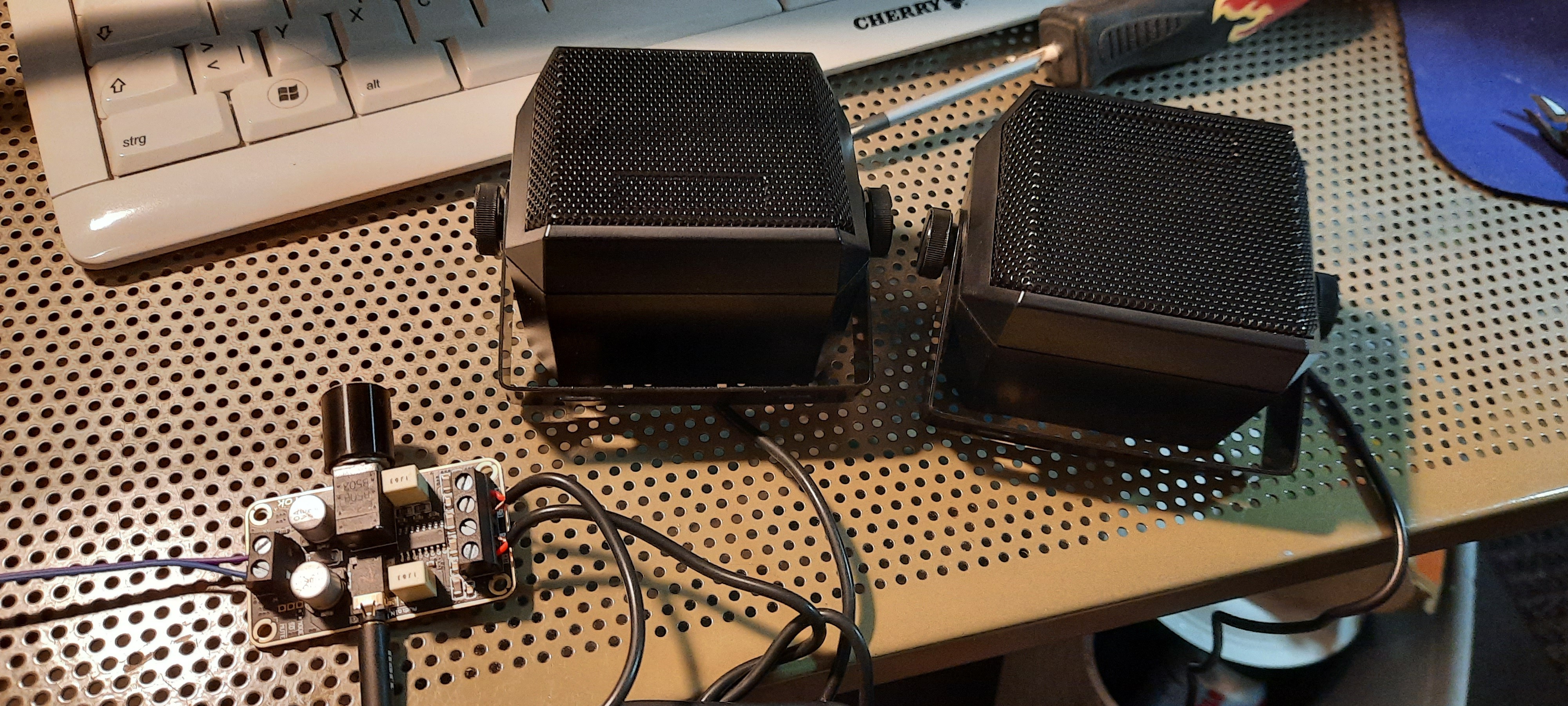
OK, so mono audio was recovered, but the CPC is really a stereo system! Hence, a decent class D stereo amp was needed - after all, I am a huge fan of computer music and computer sound & speech synthesizer extension cards (also see my project list: https://hackaday.io/projects/hacker/138722). This stereo amp looked good:
Finding small external speakers that would blend visually well with the CPC, weren't too big, had mounting brackets and swivel joints, was a more difficult task. I decided to give these a shot:
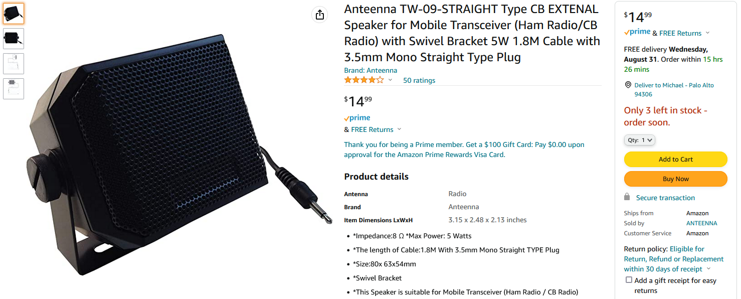
I already suspected that the drivers in a speaker intended for CB / Ham radio applications would not sound that great, and will be far from full-range with very little bass response. Hence, I proactively ordered a set of decent full-range replacement drivers of compatible size:
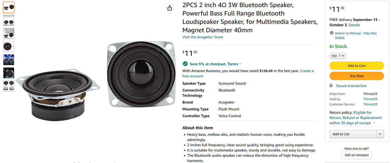
And indeed, a first test confirmed - the speakers have great clarity (good for voice in CB / HAM radio), but seriously lack bass and everything else:
 So, I replaced the drivers with my new full-range drivers. The rotary tool came in very handy again, as some case mods were required: a central support strut needed to be shortened. After that, the new drivers fit perfectly. I kept the original transparent drivers and put them in the parts bin (maybe they come in handy for another project one day):
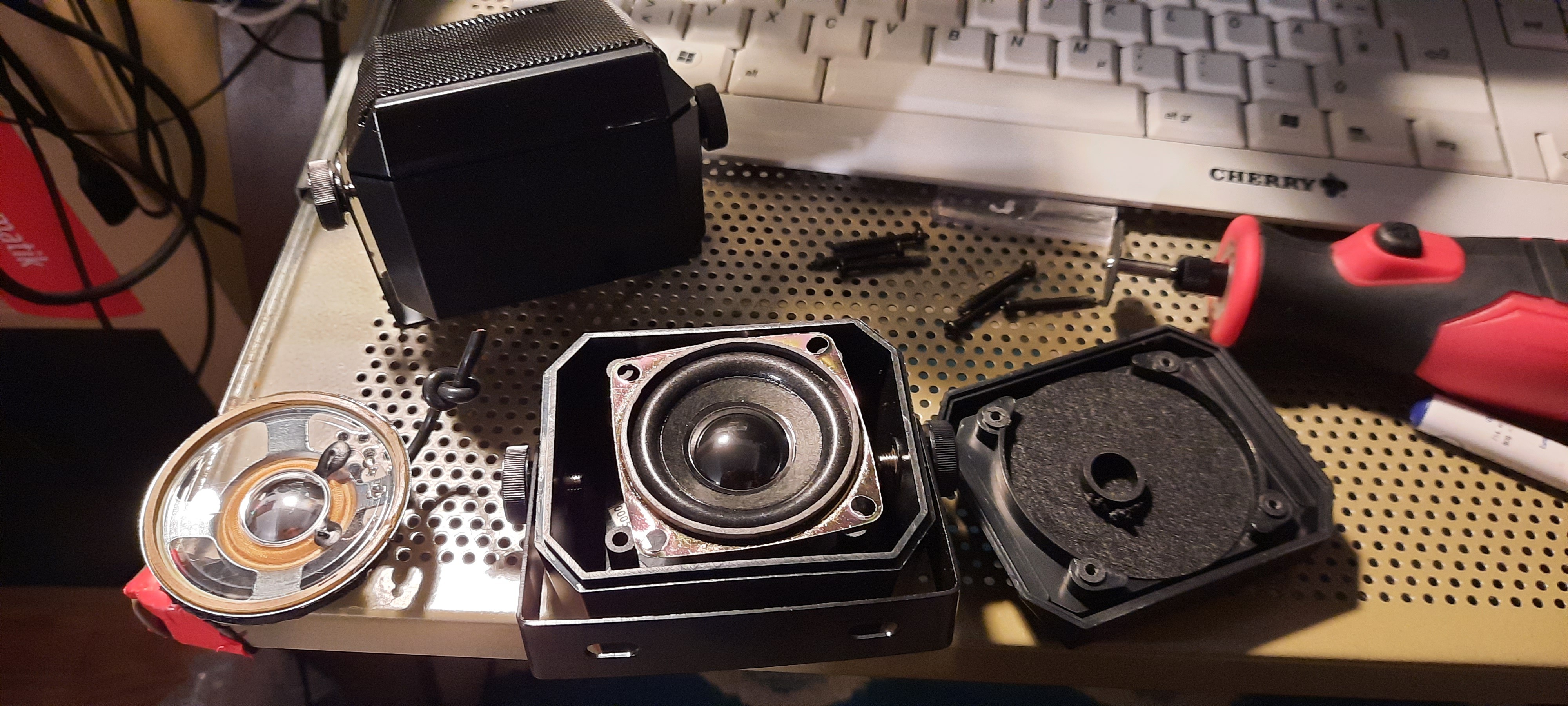
Next, I needed to find a spot for the audio amp - well, sometimes only hot glue will do! And a lot of it... see, these two holes were originally intended for my CPC RESET and DISK CHANGE buttons. Now this was the only spot where the audio amp would fit, depth wise, so I moved the buttons to the right (2 more holes were drilled...), and used the existing mounting holes for the audio amp:
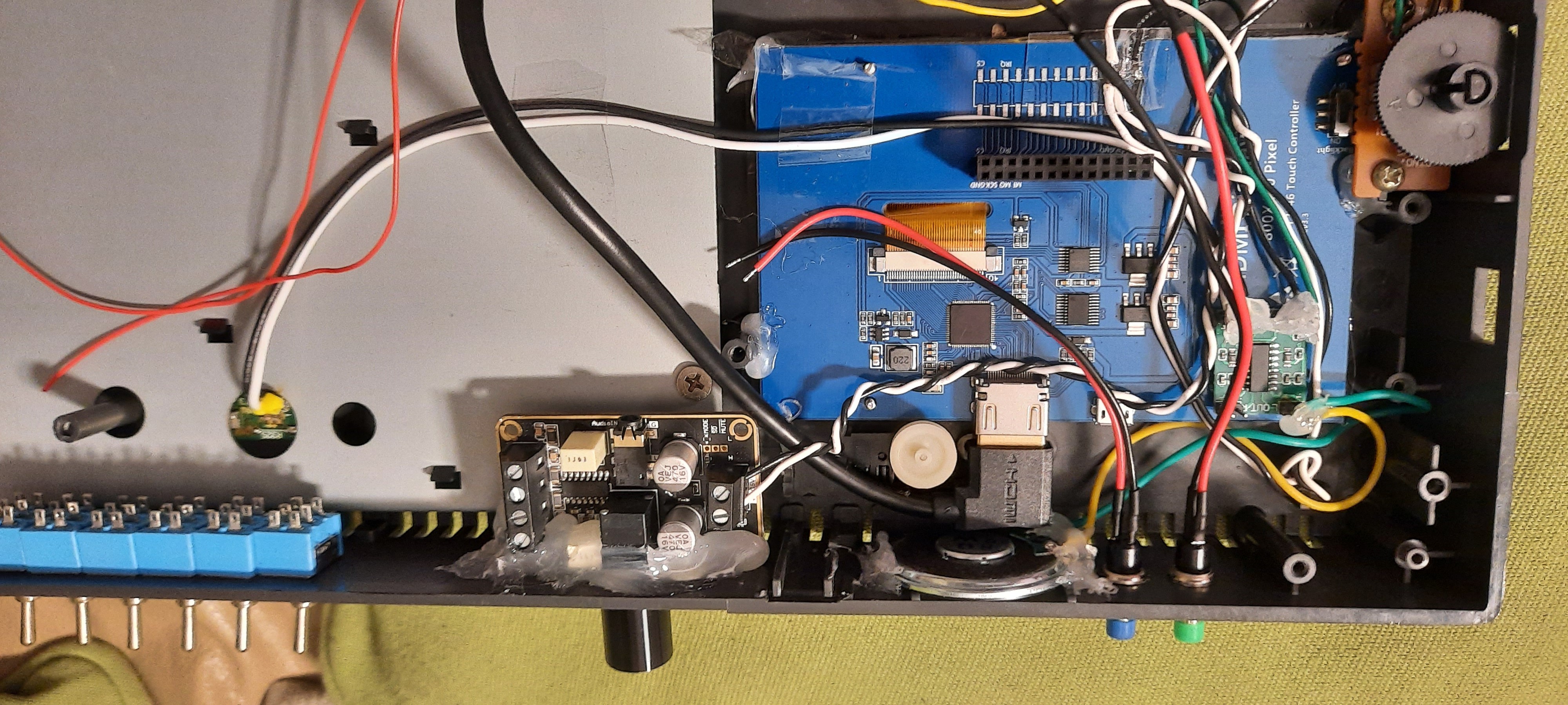
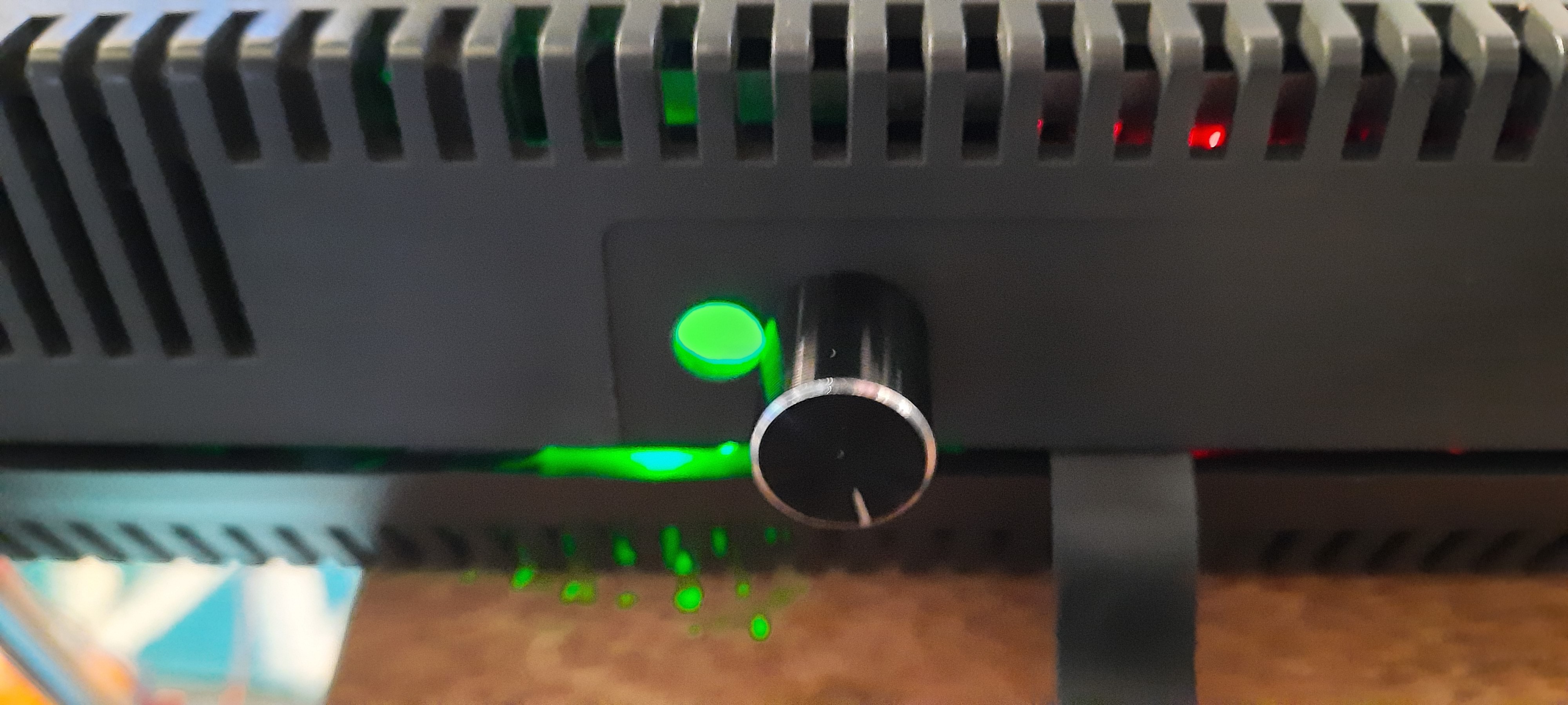
A totally unintended surprise side-effect - the hot glue nicely disperses the light from the audio amp's on-board power LED, giving the impression of a HUGE POWER LED on the back of the CPC - love it! Who would have thought that the second mounting hole would find such an unintended purpose after being filled with hot glue.
A first test confirmed that the stereo sound system sounded great now thanks to the new full-range speakers:
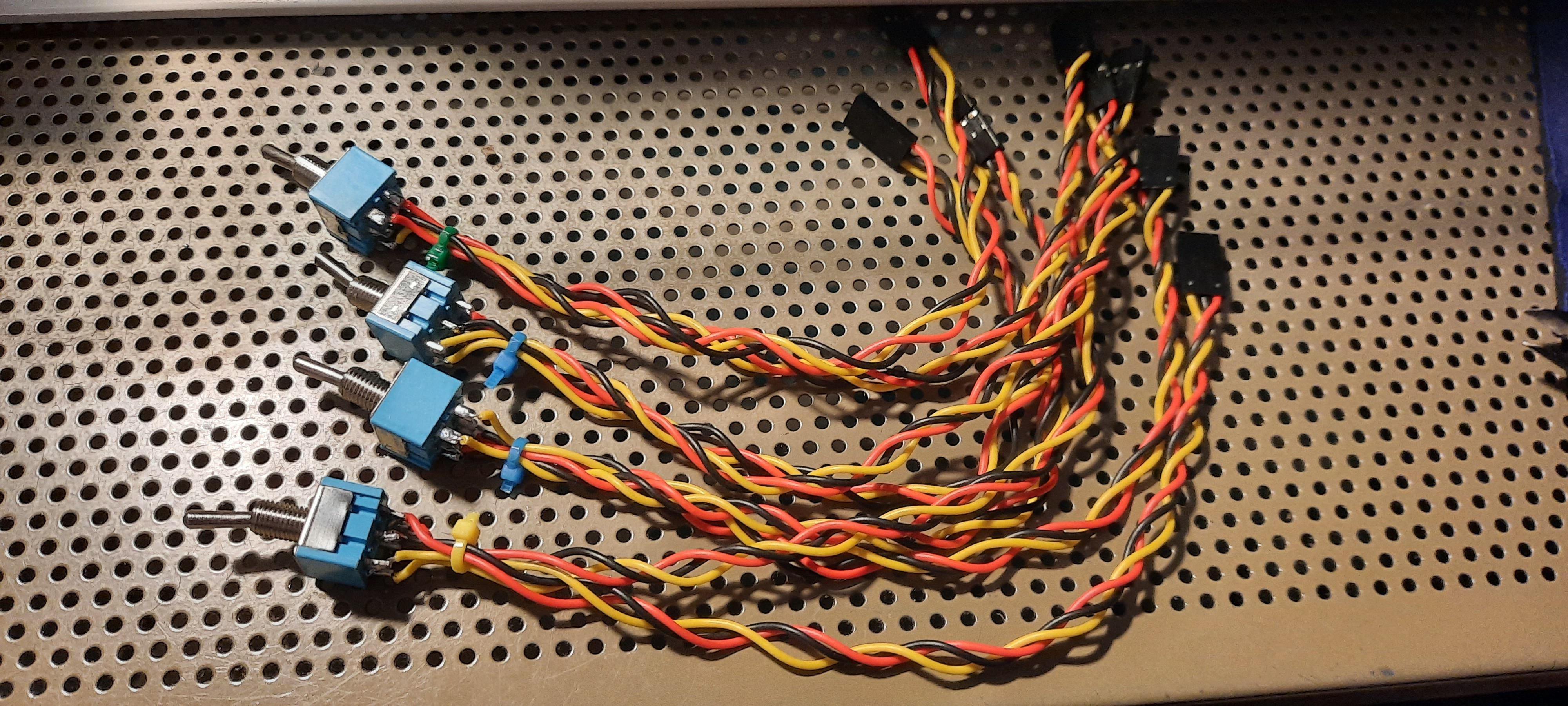
It all came together. nicely... next, I needed to wire up the switches and buttons to the extension cards. These PC motherboard Dupont cables are perfect for the job. I cut off the Dupont connectors on one side, and soldered the 2x3 row switches to them; so it takes 6 cables per switch. Cable ties provide some strain release:
Unfortunately, the original little mono audio speaker didn't fit in any longer due to the HDMI cable taking up too much space. So I needed to find a slim-line speaker replacement - this one fits perfectly into the original loudspeaker mount:
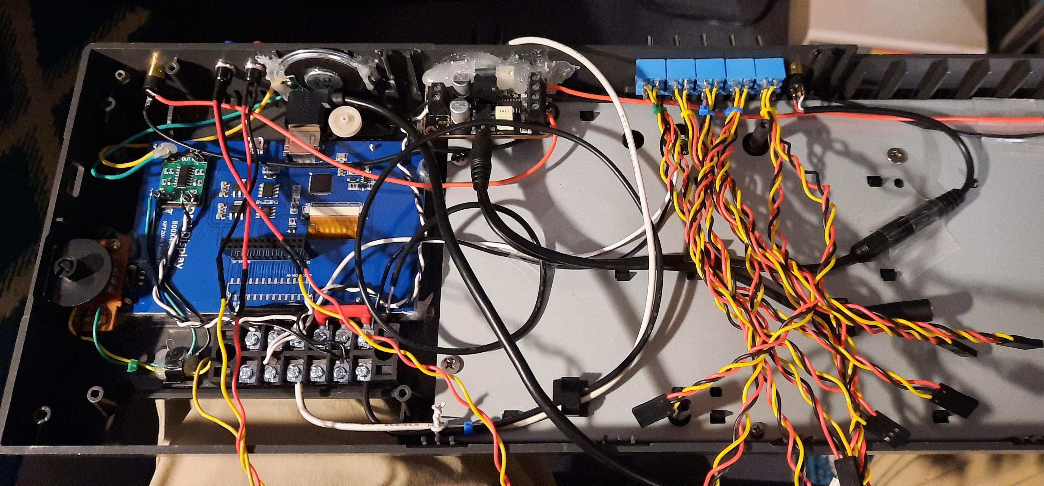
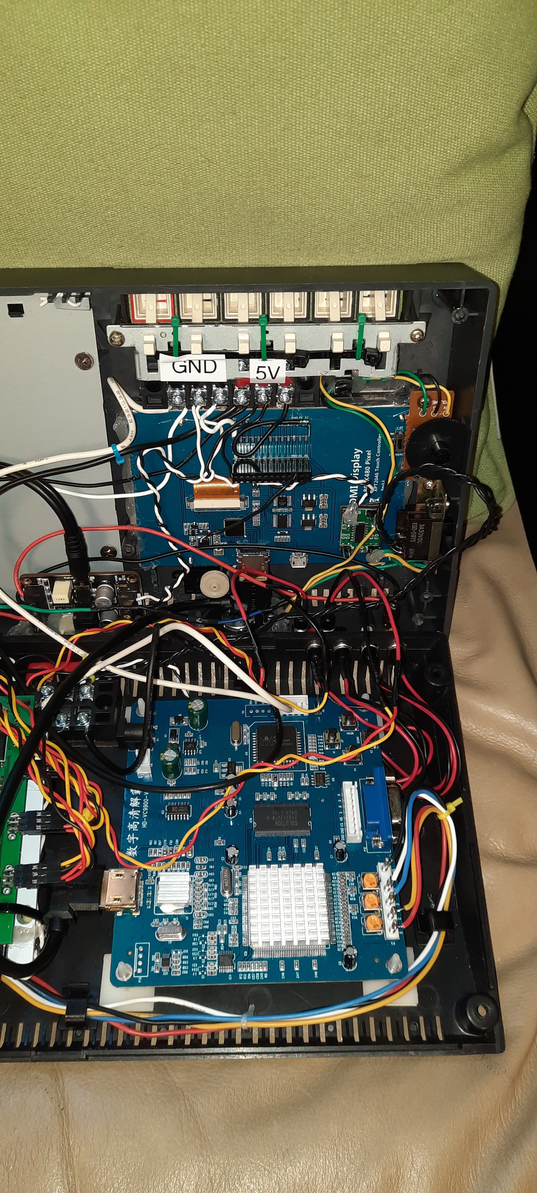
It all got a bit crowded and busy in there... I realized that the project might fail without good cable management. I invested in power rail screw terminals, as I wanted to be able to remove the top shell easily from the CPC without soldering. Same for the switches. Moreover, sockets were put in for the external loudspeakers and another mini stereo socket for external audio stereo input, e.g., from external sound cards such as my Speak&SID https://hackaday.io/project/168296-speaksid-cpc
Originally I had planned to put in a 3- or 4-channel audio mixer as well, but there simply wasn't enough space anymore. In order to listen to the CPC and to an external audio source at the same time, a simple Y-splitter cable was connected to the amp's input instead. One input goes to the stereo audio signal from the motherboard, and the other one to the external audio input. Mixing these two stereo signals via the Y-cable does result in a somewhat fainter audio signal, but the amp was still able to recover both "mixed" signals to decent volume levels. Phew!
So, after another round of cable management, it seems everything finally found its spot in the case! Are we done yet? Almost!
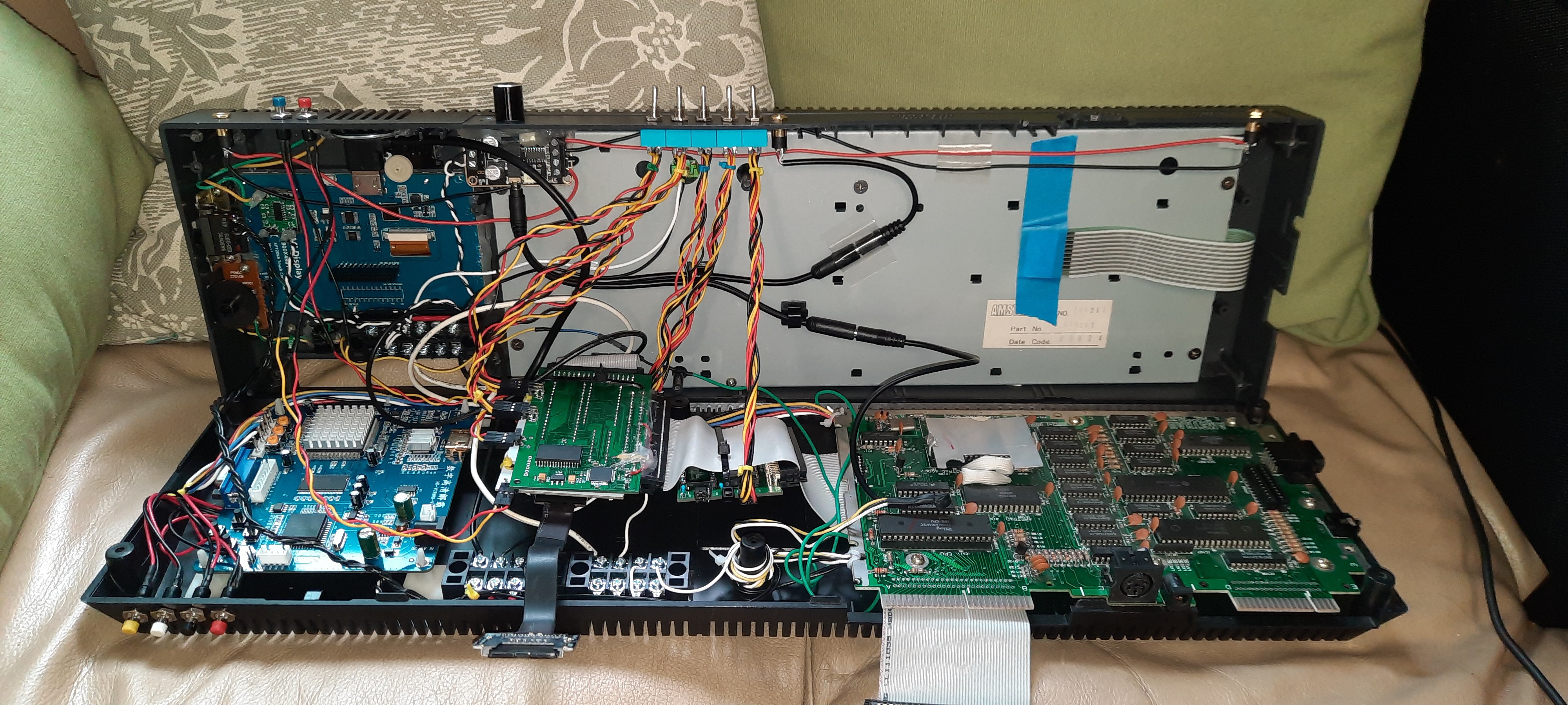
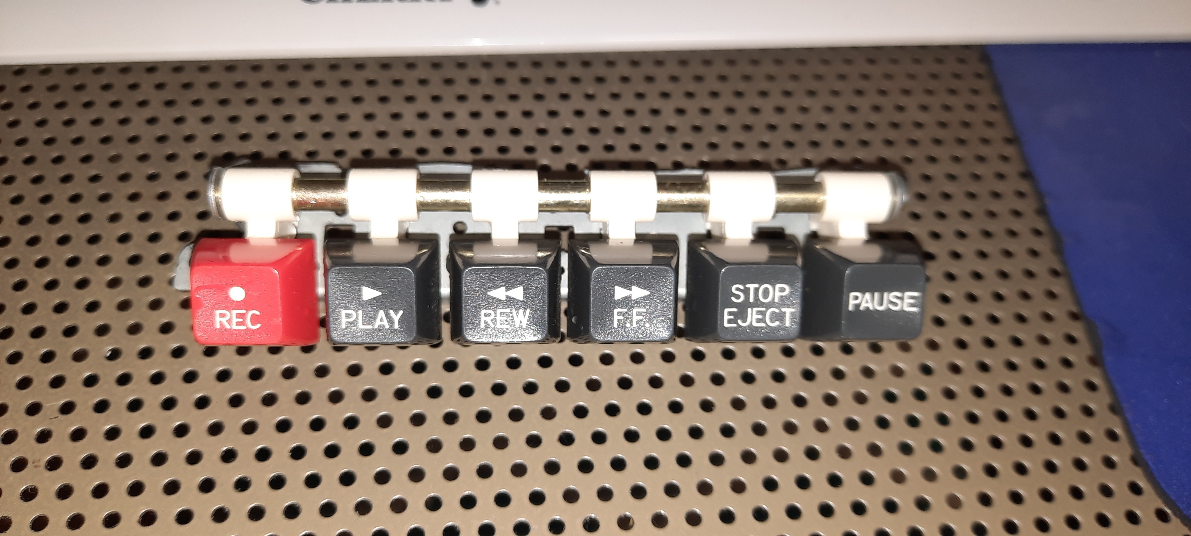
But then, there was one thing missing - we can't leave an empty hole in the case where the cassette keys used to be:
At first I was thinking to put some extra display or control buttons in there, ideally using the original keys. But the case was now becoming extremely busy and too crowded, and I wanted to call it a day. So I grabbed the rotary tool again - this time testing its ability to cut thicker aluminum... and it didn't disappoint me:
With the datacorder keys back in the case, just for aesthetics and the overall look, another round of cable management was required - I needed to relocate the top shell power rail screw terminals one more time, and also rewire the power cables to the display and audio boards once more:
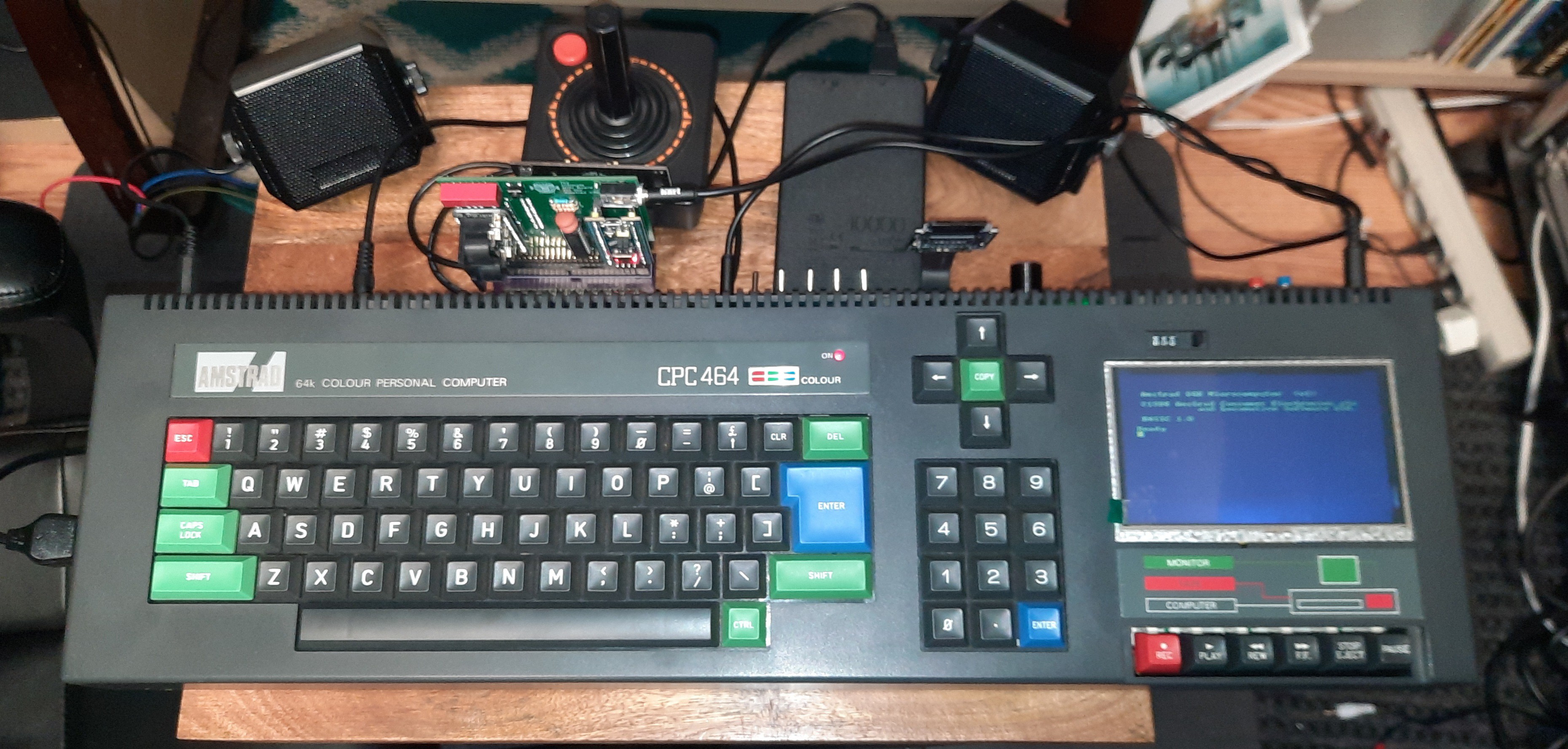
Can we close the lid? Yes, we can!
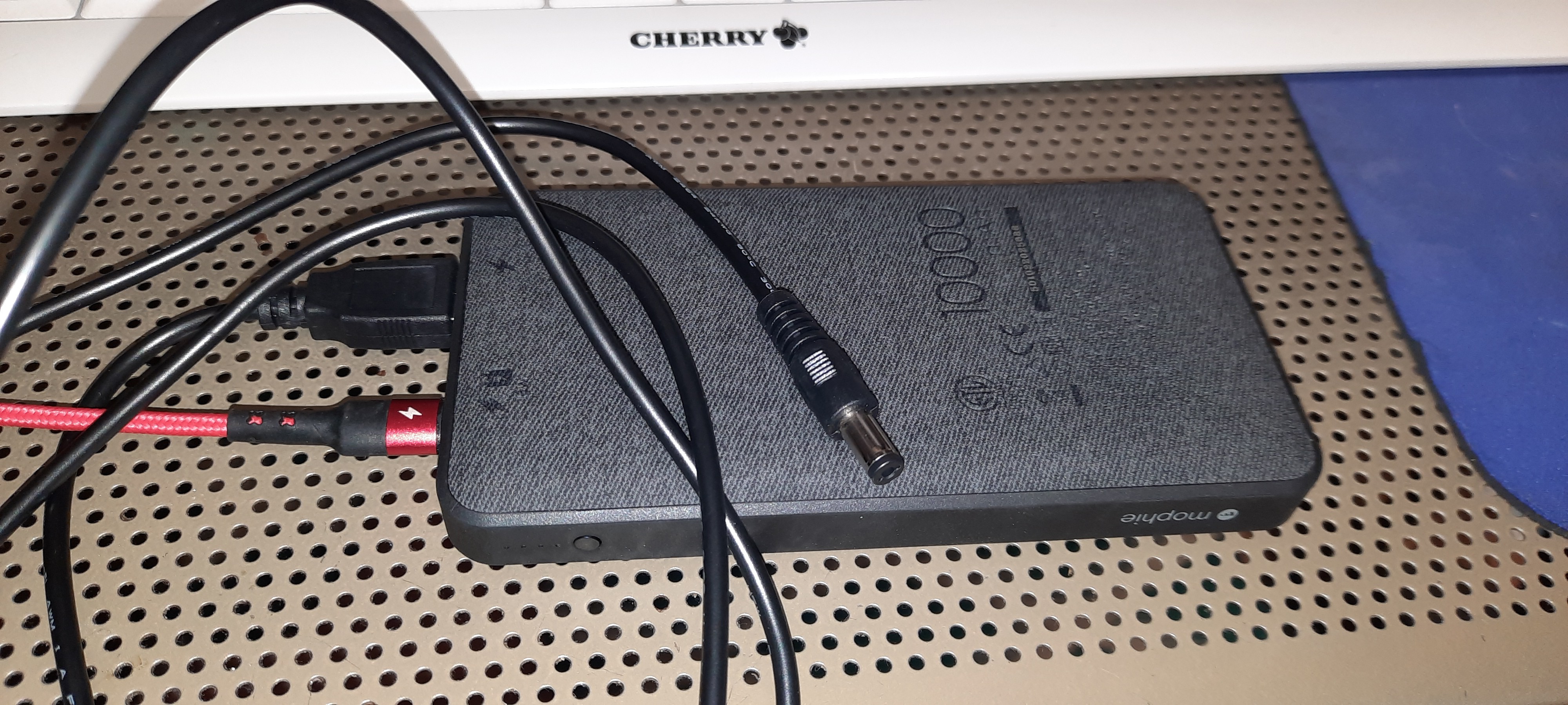
Obviously, a truly portable CPC would require some sort of battery. A friend of mine mentioned that he is using these on all of his Robots, and that they are delivering well:
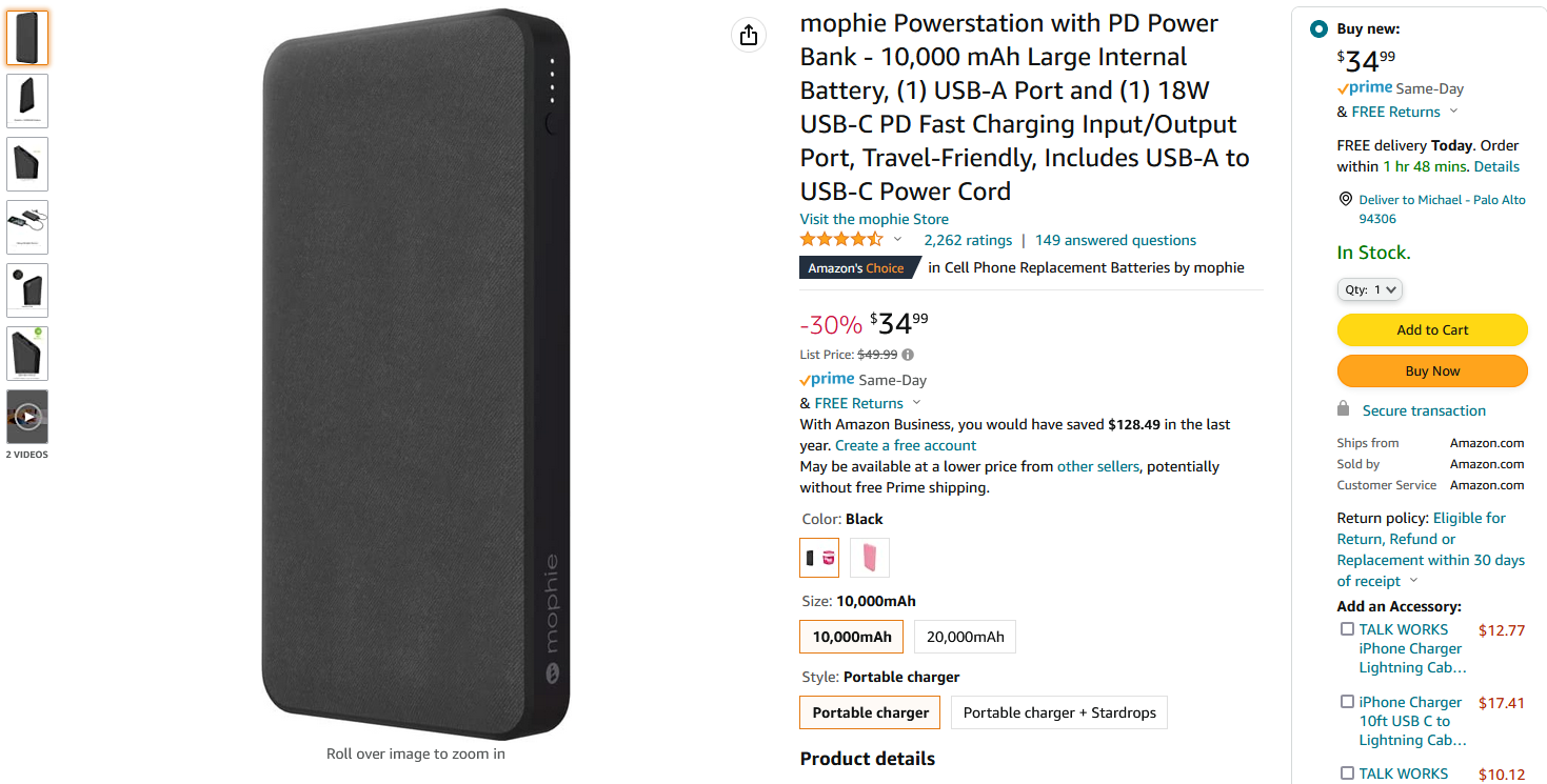
Equipped with a simple USB-to-5V (Center Positive) power cable, this directly plugs into the CPC Power Socket, no further conversions required. And indeed, this Powerbank is able to provide the CPC Portable with ~ 3 to 4 hours of runtime. Good enough for a game of "Oh Mummy!" at the beach I would say!
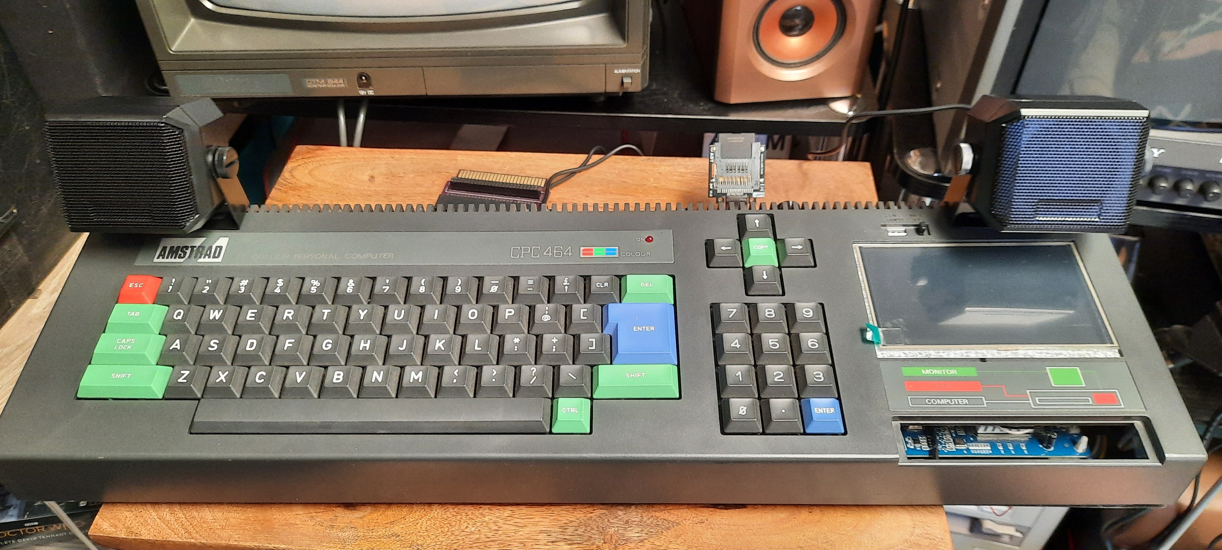
So, here we are - after 40 hours of labor later, The World's First Amstrad CPC Portable is fully operational!
The speakers are attached with Velcro and are easily detachable with their mini stereo jacks, so you don't need to take them to the beach if you don't want to - after all, you will always have the built-in mono speaker as well!
Thanks for reading! Happy Hacking!