 colton.baldridge
Some of you might be wondering, if I had MVP 5 months ago... what happened to the OS3M mouse? And I'll tell you - my life got busy! Work on the project stalled for a few months following the last update. I reached a point where I knew a hardware revision was the right path, yet wasn't ready to take the plunge and actually do it with everything else I had going on. But, now that pretty much all daylight is gone here in Seattle, I don't feel bad about sitting inside after work! So, over the past month or so, I crafted the next revision of the OS3M mouse. It wasn't a major upgrade, but a necessary one nonetheless. I had the following list of improvements I knew I wanted to make after building and using revision 0 (the one in the MVP video):
- accidentally ordered an 0402 resistor for R1 when the footprint was 0603
- the power LED is too dang bright
- I didn't place SDA and SCL test points
- C11 - C15 were in a line that was painful to get in place
- the 2n caps on the coils should be 1n for good parallel impedance
- INTB should be connected on both LDCs for interrupt driven comms
- I should use the STM32 with larger flash (in the same package)
- add 40MHz external oscillator for increased accuracy
- add an expansion header for future external GPIOs (or whatever your mind can imagine!)
All things considered, revision 0 was a very good prototype that unlocked a lot of testing, but it wasn't good enough in my mind to be released to the public. That's where revision 1.0 comes in. It implements fixes to all of the above issues and (spoiler alert) is actually a viable release candidate! But first, I want to explain the needs behind a couple of the improvements I made.
The 40MHz oscillator is probably the biggest change from the last revision, as it is the only major hardware addition. The reason for the oscillator comes down to noise. The LDC chips used to actually do the sensing rely on a reference AC signal and compare it with the resonant frequency of the coil circuits to get their output data. This means that any deviation in the reference signal directly couples into the output data as noise. Normally, this reference signal is generated by an RC oscillator internal to the LDC ICs, but TI also allows you to pipe in an external up-to 40MHz signal, which is what I have chosen to do.
The second major change is the addition of an expansion header. It breaks out GND, +3.3V, I2C_SDA, and I2C_SCL onto a right angle pin header. This should allow anyone to add something like the TI TCA9534 I2C I/O expander to the OS3M mouse, which could unlock even more functionality. Other ideas I've had are I2C LED controllers, I2C analog inputs (for potentiometers or sliders), or even I2C motor controllers. The sky is the limit.
The design of revision 1.0 was actually a bit more involved than I initially expected. I did a full rip-up of all routing, and added in 2 more layers, making it a 4 layer board. Here you can see the revision 0 and 1 layouts side-by-side:
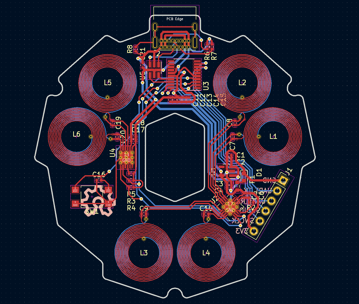
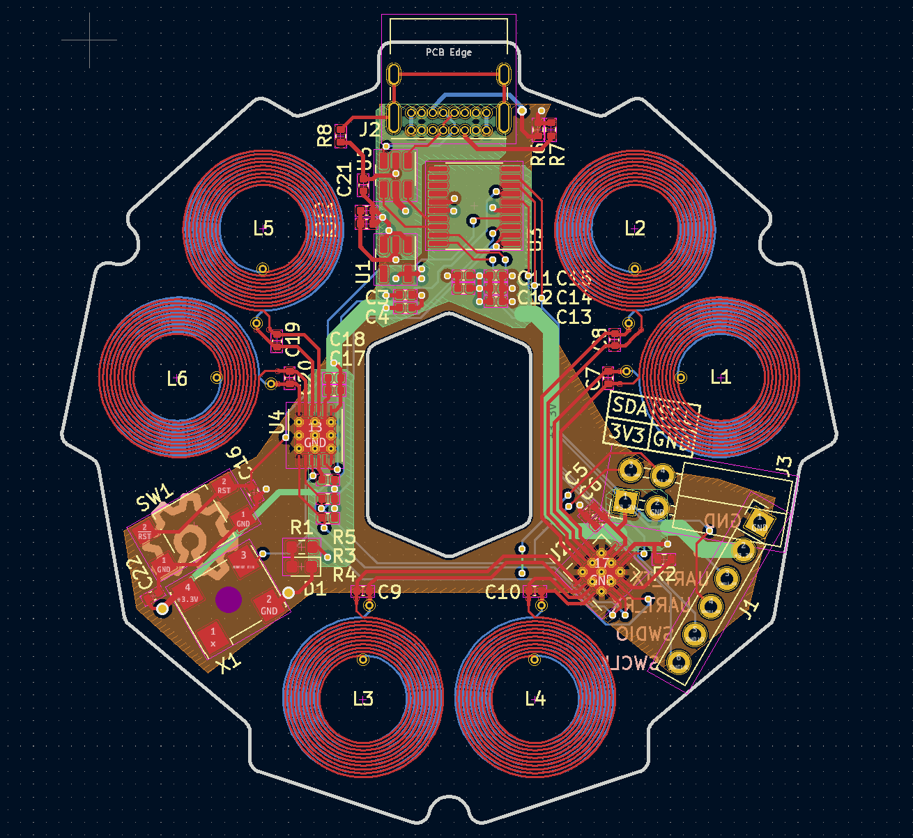
You can see the clear addition of the expansion header in the bottom right, addition of the 40MHz crystal in the bottom left, and the movement of the 3.3V LDO to the top middle (where it probably should've been from the start). You can also see the orange ground plane and green power planes in the middle layers. I was slightly worried about adding the ground planes as close to the coils as I did (violates TI's recommendations), but this would prove to not be an issue. I sent the boards to good ol' JLCPCB and got them made with a stencil to boot.
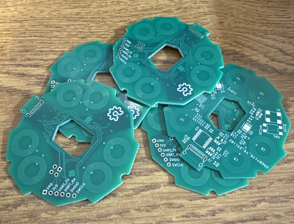
I squeegeed and soldered one up to use for development:
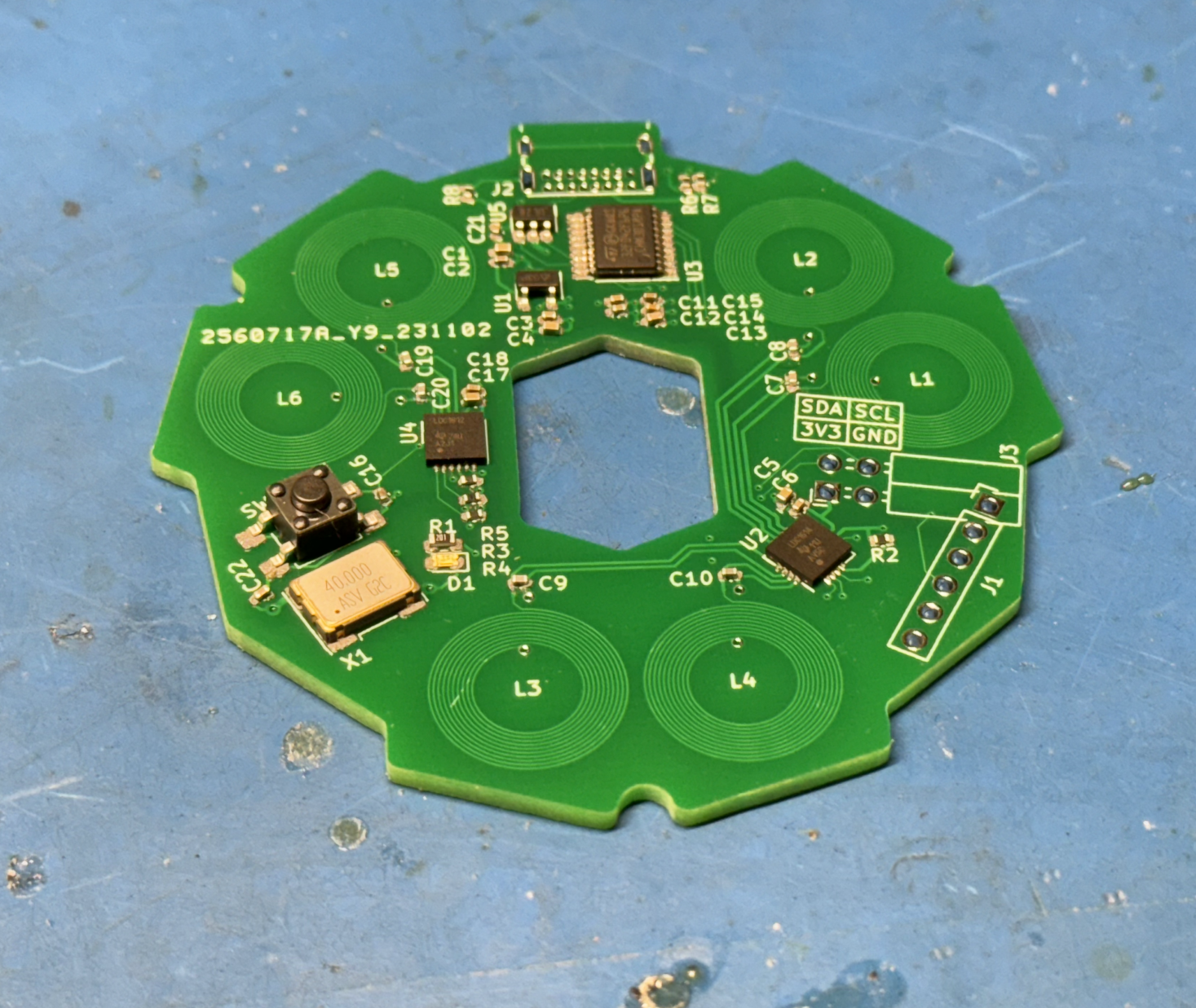
And away I went.
First development activities consisted of upgrading the project files to be compatible with the new, larger flash MCU. A task that actually wasn't as hard as I was expecting it to be. STM32CubeMX required a little finagling, but not too bad.
I then set off on enabling the 40MHz oscillator, since it was only a single bit flag to turn on. And let me tell you... it really does make a huge difference:
Before:
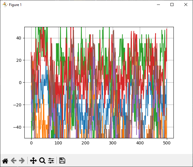
After:
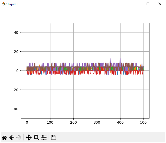
You might be asking - "ok, you decreased the noise, but why does that matter?"
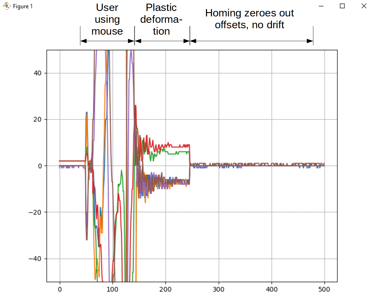
The answer lies within one of the OS3M mouse's key "flaws" - the fact that it's almost entirely 3d printed, including the flexure. When a user moves the mouse and lets go, due to a small amount of plastic deformation, the mouse doesn't return exactly to center. In order to fix this, I need to rely on software to determine when to "re-home" the mouse to its new center and prevent drift. And in order to know when to "re-home", I need to know when the user is using the mouse or not. The easiest way to do that is to look at all the channels and see if they all fall within what I consider to be the "deadband". Previously, when I took this approach, the noise from the RC oscillator made it so that the range of noise received was outside of the deadband and thus it was impossible to distinguish between the user using the mouse and the user not using the mouse, just reading the noise. Now, it is night and day when the user is touching the mouse and not, even the smallest touches register. Here you can see the homing in action:
And with that, I am proud to say, the OS3M mouse works and is ready for release! Check out this cool video I made explaining the project:
Obviously the project is far from done. The firmware is not great, doesn't support interrupts (though the hardware is there), is still using STM's HID mouse example as the backend, and is not very easy to expand on for any expansion functionality you want to add. The software also is only a command line application which only supports SolidWorks, whereas I have a dream of a GUI with configurable gains, many programs supported, and expansion button configuration. The hardware is also still not perfect, as I haven't updated the base to support the extra expansion header either. But, I felt the need to update everyone so they know the project isn't dead, and is in fact alive and well!
Thanks for reading!
Discussions
Become a Hackaday.io Member
Create an account to leave a comment. Already have an account? Log In.
I tried to place an order on JLCPCB using the updated Rev2 PCB info, and it kicked back with stock issues for a few items, one being the rather critical ADC chip, but also simple things like the push switch. The crystal is listed as no longer manufactured.
That said, the gerber processed with no issues.
Are you sure? yes | no
Great progress!
Re: plastic deformation. I'm thinking that spring-lever type centering device for each axis might lead to more accuracy in the homing. This is similar to the spring-lever centering that is used in RC car controllers for their steering. See here: https://youtu.be/-_nmAR-dy48?si=wSOH_7ayNMsj9EwN&t=166
However, it will require some engineering to create a 6DOF centering using similar ideas.
Are you sure? yes | no
following below comment: information item: Top: 18.7%; > 35% recommended
Bottom: 15.4%; > 35% recommended.
warning item:
NET-(C8-PAD1), NET-(C8-PAD2)
same for C19, C20, C7,C9,C10
I won't feel offended if you remove these comments, just thought it might help :P
Are you sure? yes | no
I uploaded the OS3M_Mouse.kicad_pcb (0c2598c) file into the https://aisler.net/ calculator tool and got following warning / information item:
(disclaimer: I have no idea what I am talking about, just thought that it might make some sense to you)
! Netlist-Layout-Deviation: Shorted Pads
"We detected deviation(s) between the netlist and the processed layout of your pcb. At least one of the listed nets shares at least one pad, which is conductively connected the other net. Please check your layout before ordering"
i: Unfavourable copper allocation
"Your layout shows large areas of low copper usage on at least one outer copper layer. If your layout allows it, we recommend that you fill open spaces with copper."
Are you sure? yes | no
Ordered populated boards from JLC. You should add the pos files (CPL) to the github, I generated my own in kicad and omitted the J L and X components. It looks fine in the previewer but I barely know what I'm doing
Are you sure? yes | no
It seems to be more than sensitive enough as is, but was there a reason for sticking with 2-layer coils when moving to a 4-layer board?
Are you sure? yes | no
Great question, a couple reasons - one being that 2 layer coils work, so I didn’t feel the need to change it, and secondly, the program I wrote to generate the coils (since kicad doesn’t natively support it) only works on 2 layers. I did see someone recently forked my repo though and added support for 4 layers so I might consider using that in the future!
Are you sure? yes | no