 whoobee
Bill of Materials:
- Jetson Nano (I have the old 4GB model, but 2GB should also do just fine)
- Waveshare 7.9" display
- 60% Keyboard (I used the Epomaker GK61 with Bananaswitches and Honey-Milk keycaps)
- Trackball: Perixx PERIPRO-506 USB Trackball
- Power bank POSUGEAR Mini Power Bank 10000 mAh ( Even though, in hindsight I would pick maybe something else with higher power supply support on the USB A ports )
- 2 to 1 USB switch selector: Kcleve (just some random 3.0 USB switch)
- USB Hub: ICZI Mini Square USB 3.0 Hub
- USB A to USB A for the switch selector: SUNGUY USB 3.0 Cable Short, 0.3 m
- 2 x USB A extender cable: SUNGUY USB 3.0 Extension Cable 0.3 m
- Display Port to HDMI adapter: Warrky (although I tested the output and it seems to not work for now, I need to check a bit more what is the exact reason)
- various m2.5 and m3 screws and embedded nuts
- and if you plan in the future to expand it, it is better to think about using connector plugs for easy disassembly
Overview
The design I made it in Fusion 360, but since my industrial design skills are limited I did not save the history in order to make this design parametrized.
For a short overview of the components you can see this short video:
Top Assembly
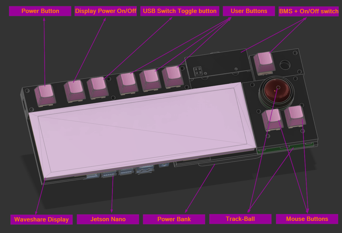
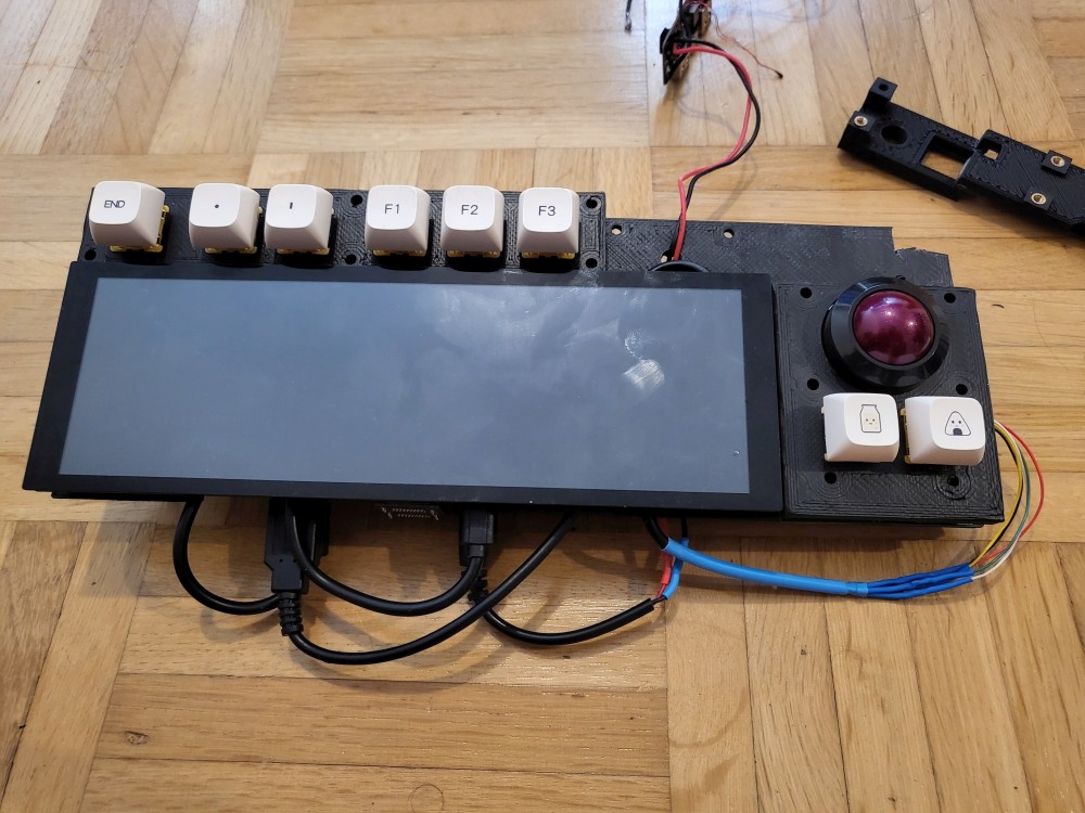
Initially I started with the top assembly which contains the Jetson Nano, the screen, power and the IO (power buttons, track-ball, user buttons, etc.)
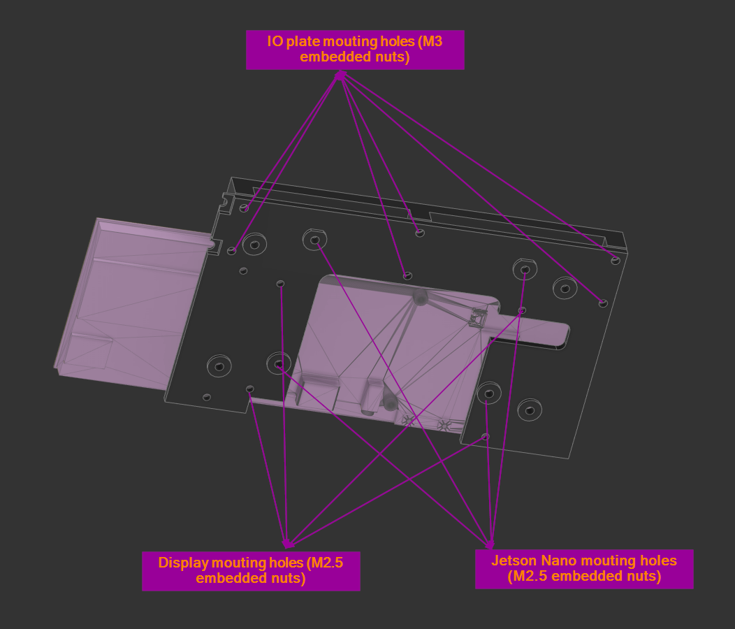
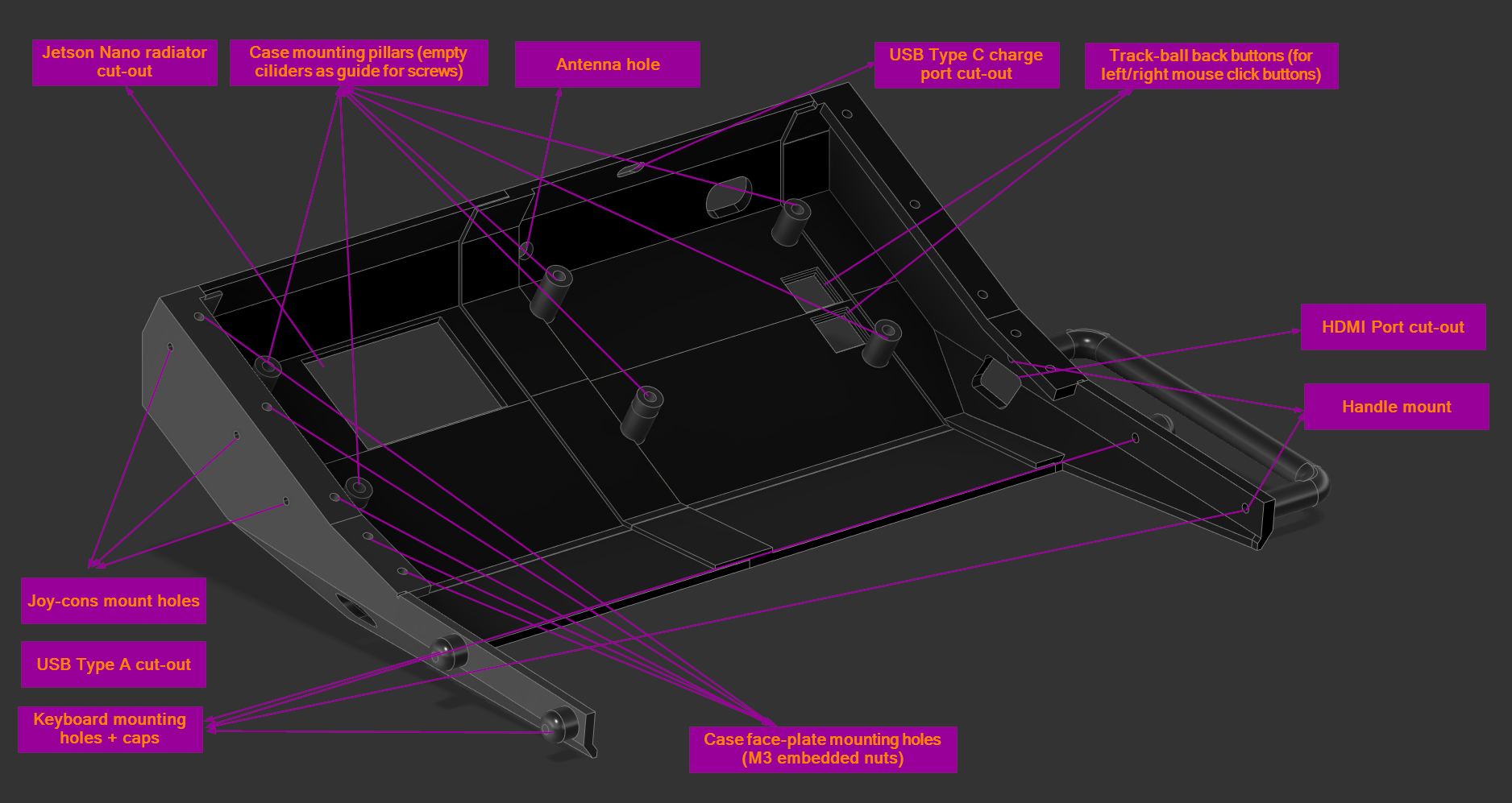
You can see the top plate mounting holes explained here:
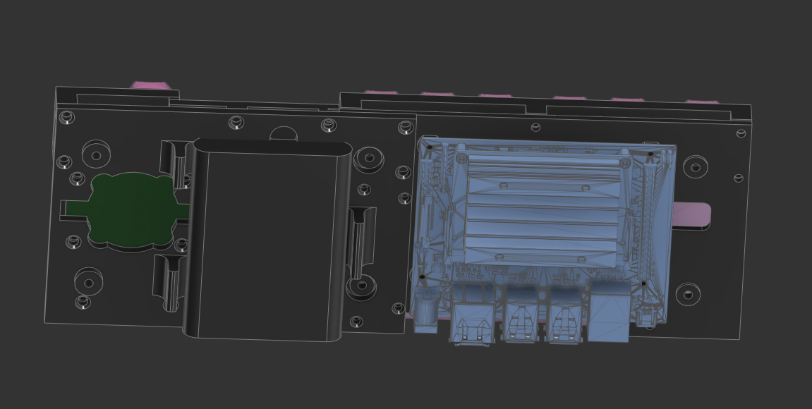
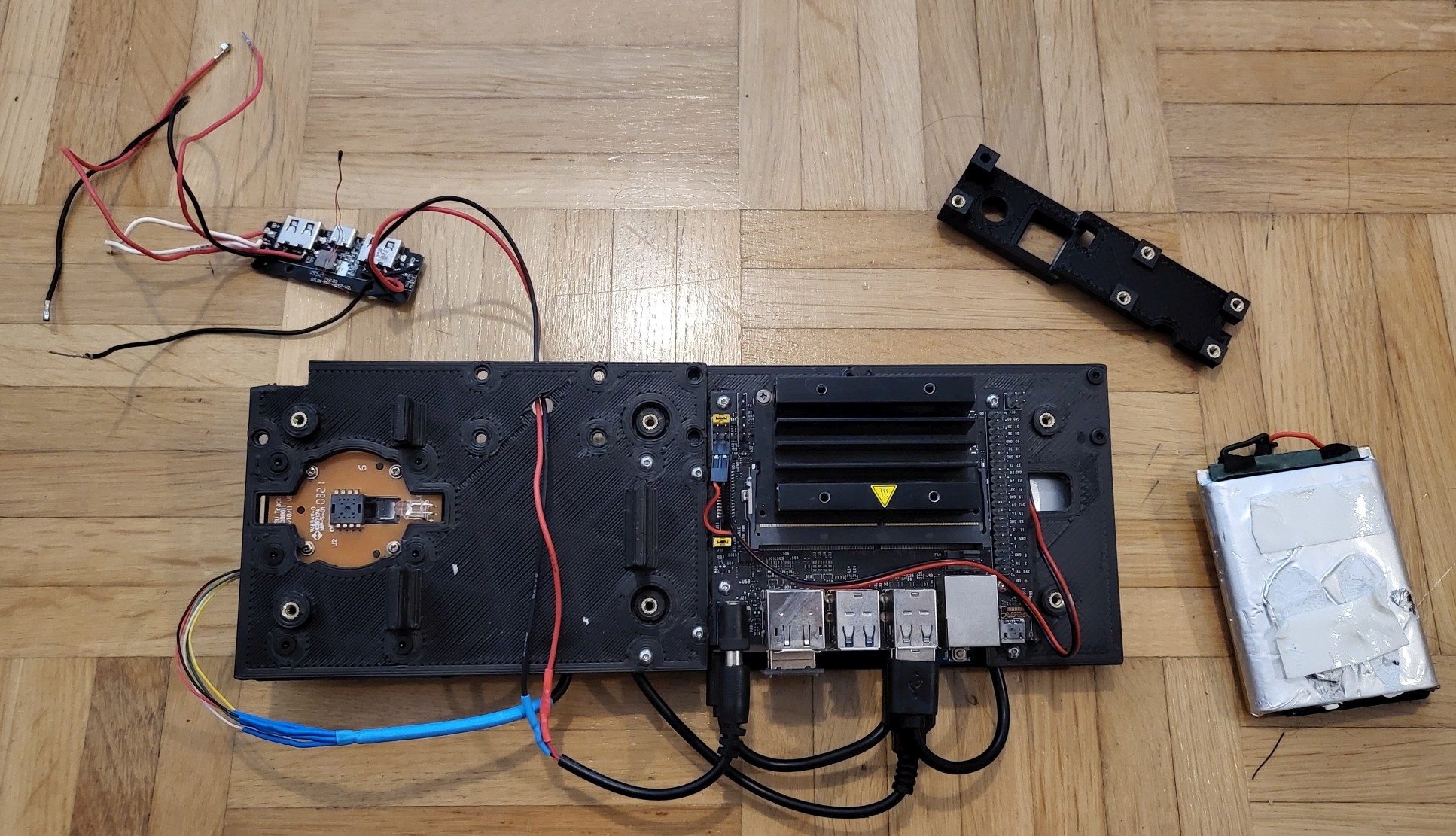
and on the back side you can see the components a bit better:
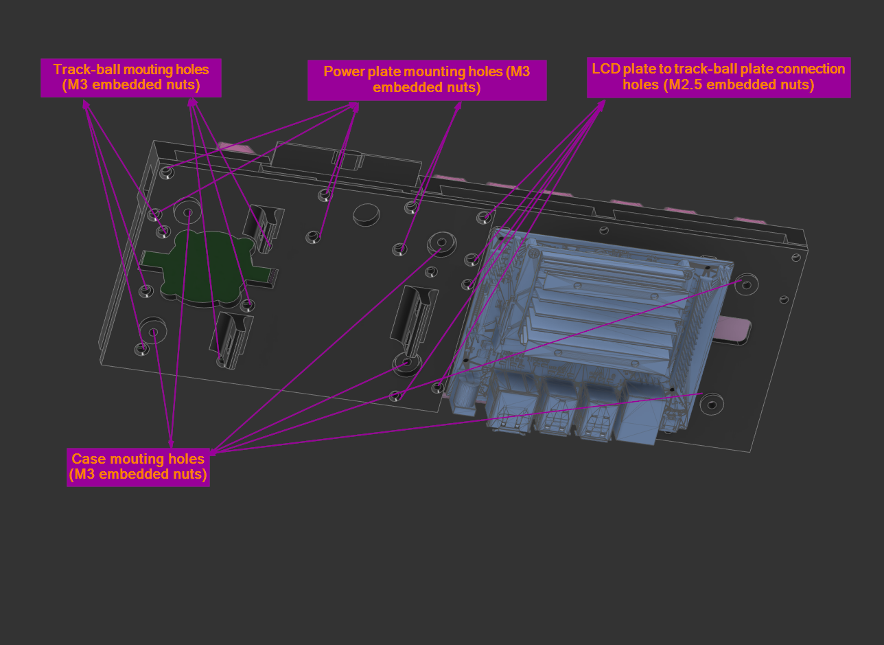
To have a better understanding on how the different parts are connected together I also made a short print screen with the rest of the mounting holes labeled:
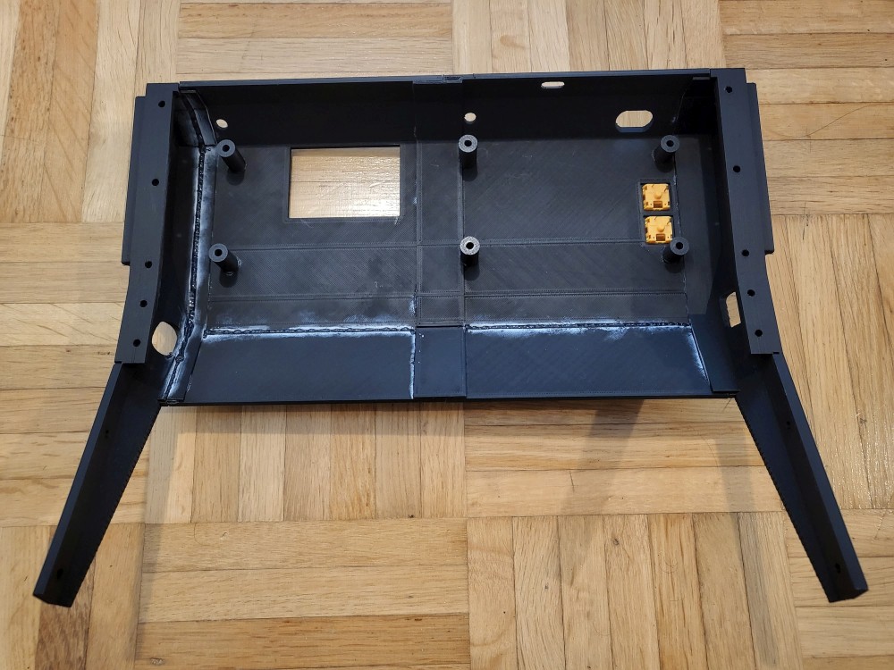
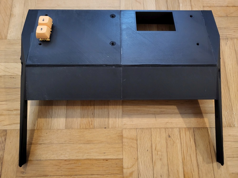
Here are also some real life pictures with the top assembly printed and everything mounted:
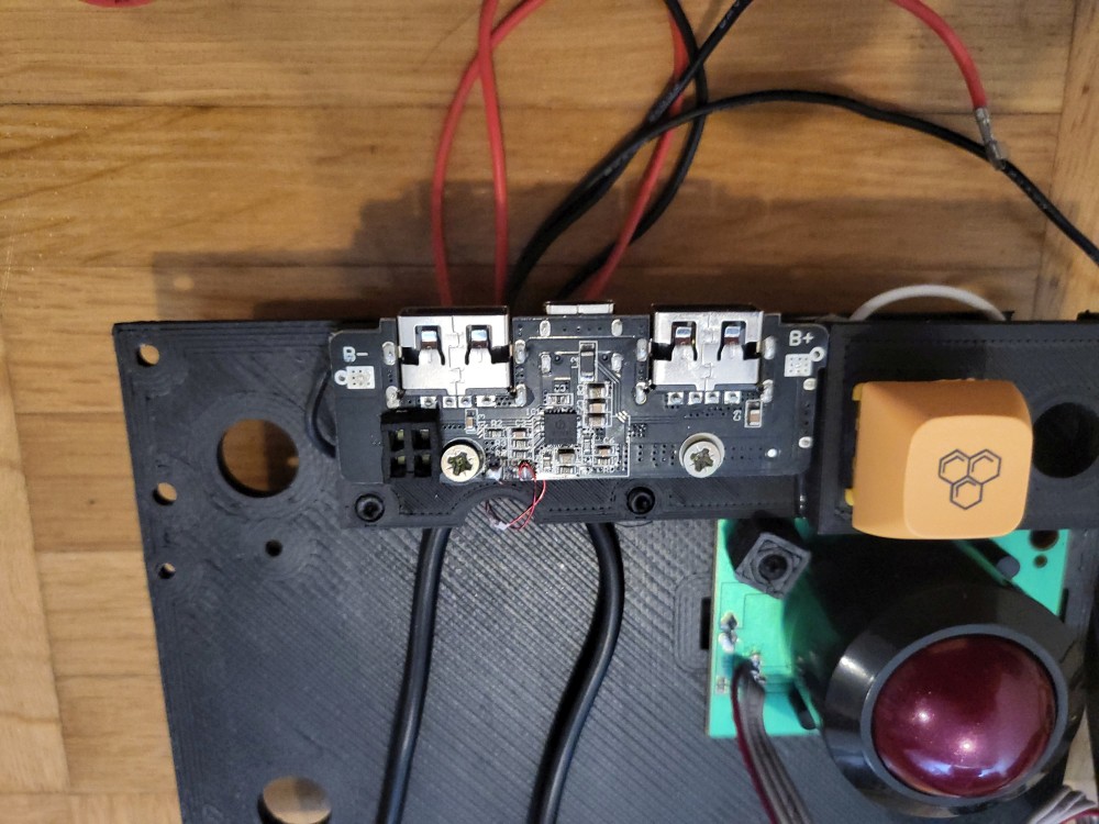
- for keen eye, it can be clear that one of the mounting holes of the power plate (bracket which contains the BMS mounting holes and the power On/Off switch) is missing. This error is still in the design, so you either grab a wire clipper or change the design before you print it :) In my case waiting for another 3h print was way too much...
- here are some pictures with a better look at the BMS and the different wires connected to it. I have no wire diagram, but it should be pretty straight forward.
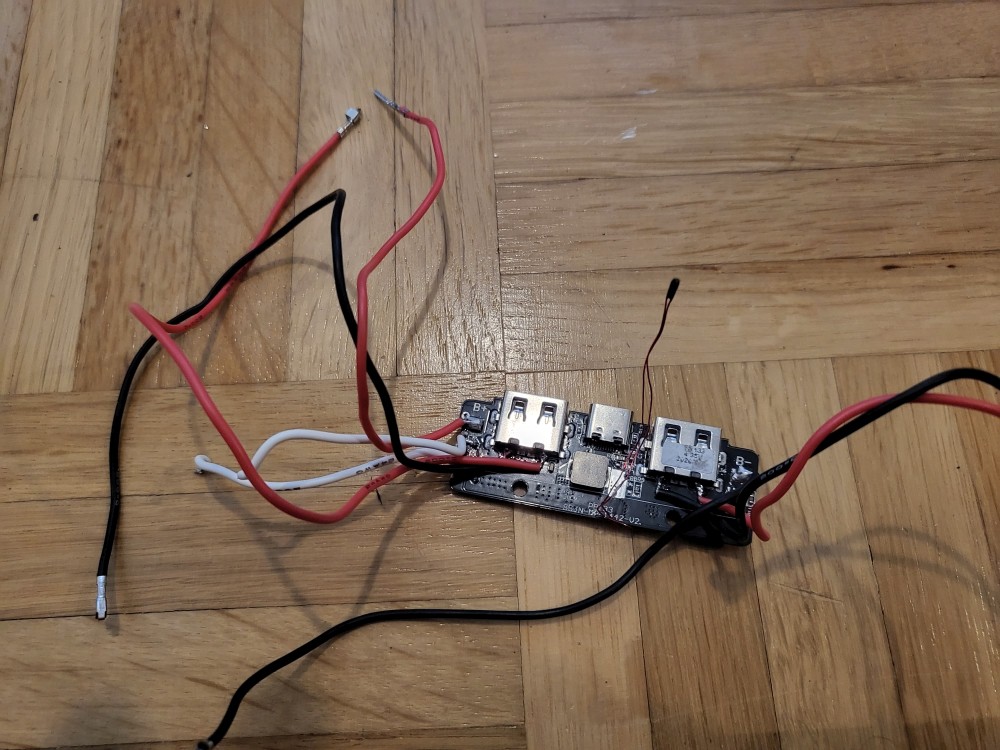
It goes without saying that you have to be VERY careful when you work with LIPO cells, especially when they are not protected. So please do it at your own risk ;)
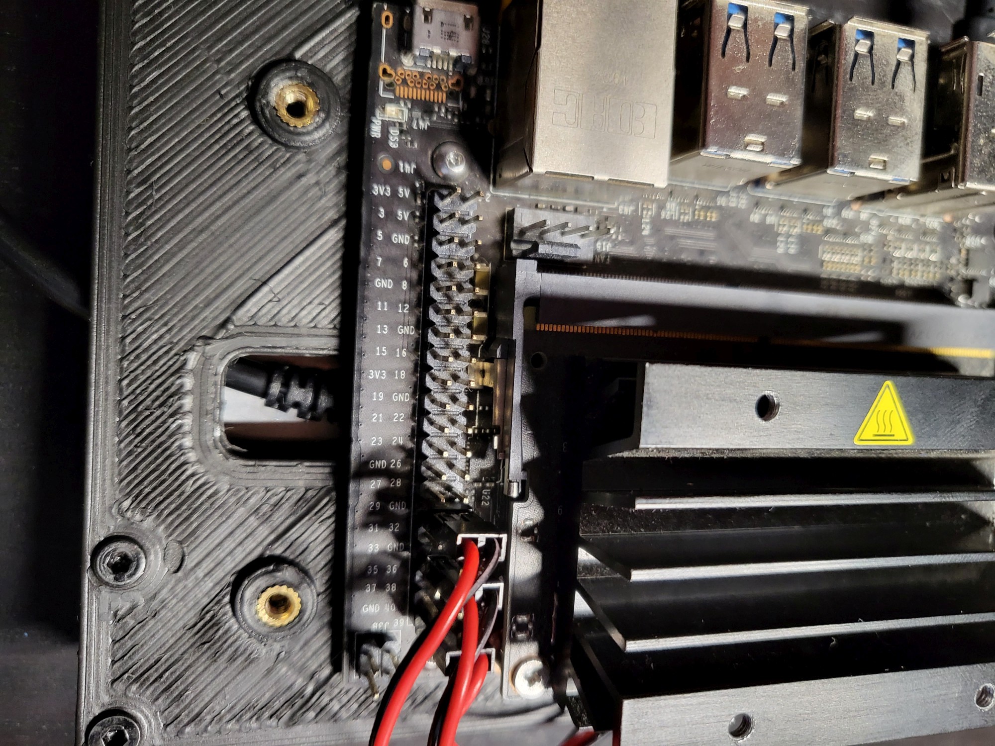
- here is the back side of the assembly where you can see the Nano mounted and the LiPo on the side:
- the user switches are connected directly to the Jetson Nano GPIOs. I used pull-up resistors, si in my case initial state is High.
The F keys are comnected to the buttons as following:
F1 - PIN29 (BCM5)
F2 - PIN33 (BCM13)
F3 - PIN40 (BCM21)
Bottom Assembly
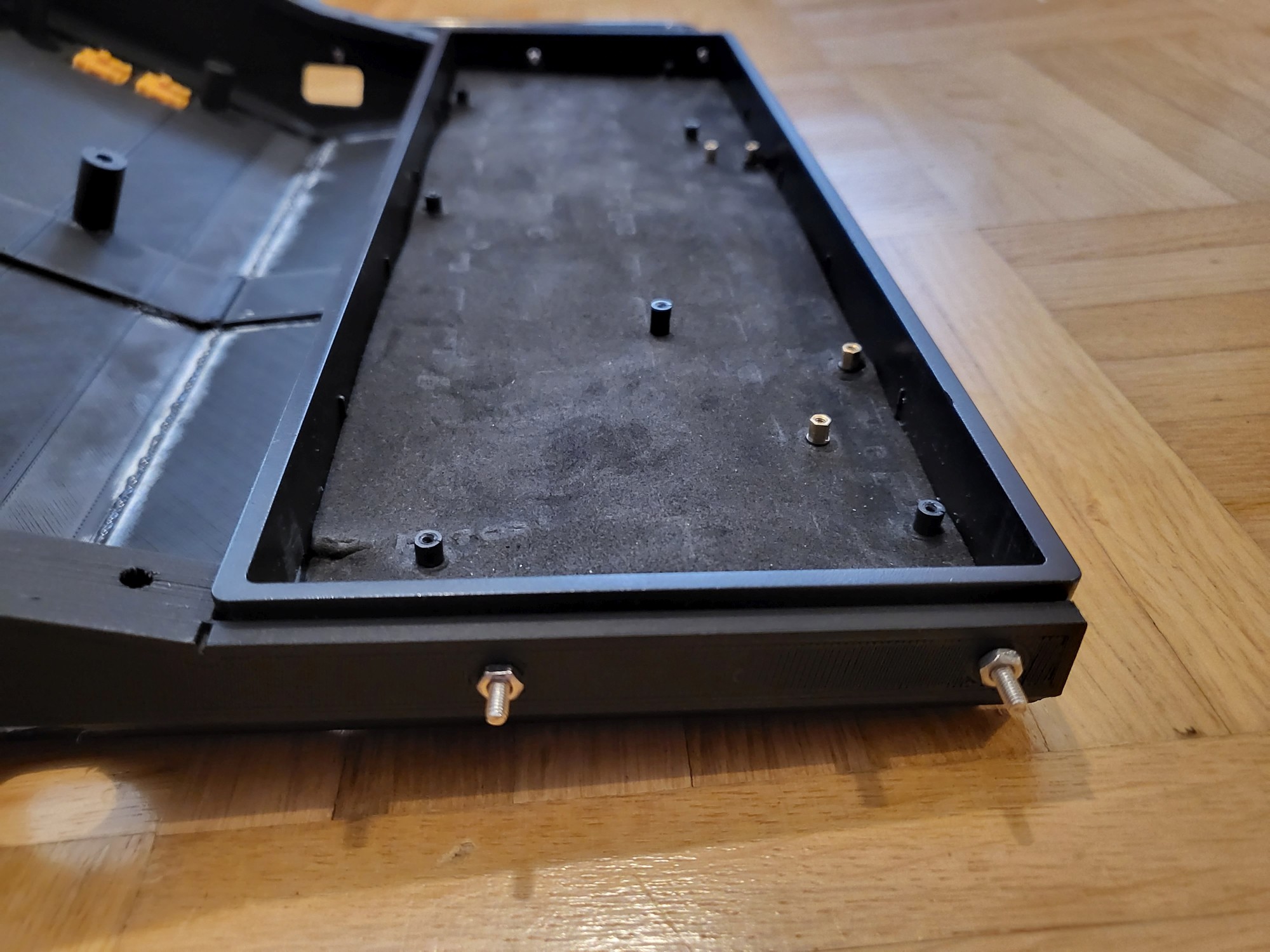
For the bottom assembly, it is quite straight forward, it is purely just the keyboard, which you need to disassemble and drill some holes to connect it to the main case.
Here are some pictures with the actual holes. The edges must be a bit chamfered in order to not interfere with the keyboard switch plate and PCB.
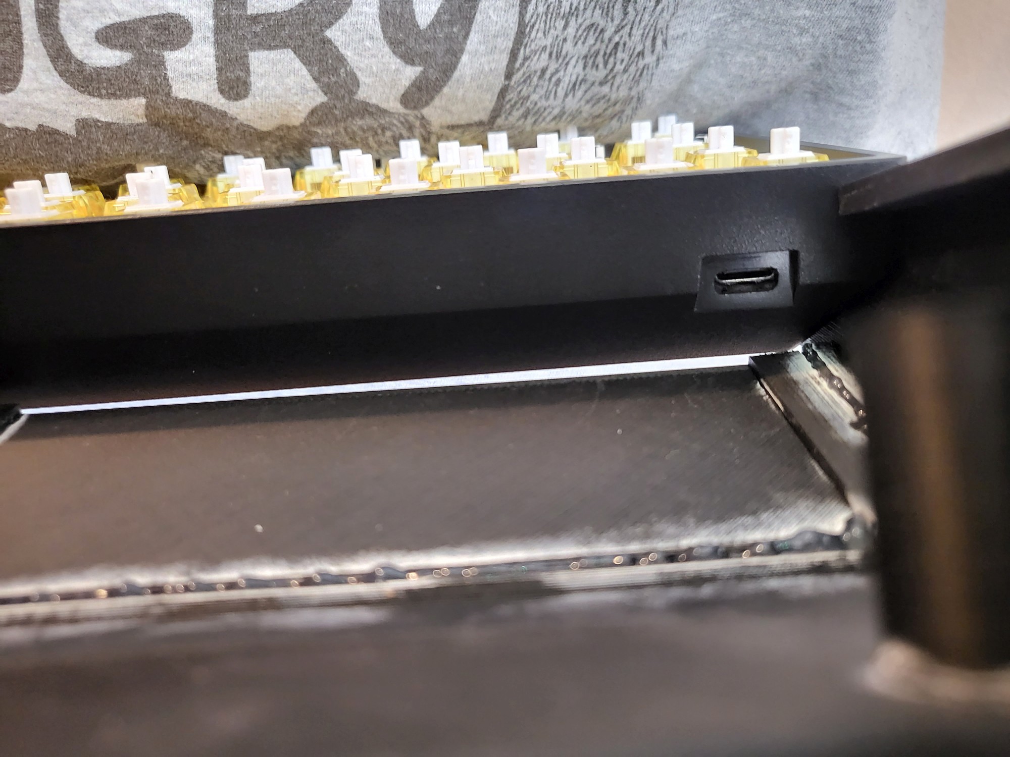
Also pay attention that the USB connector of the keyboard PCB is actually alligned with the case cut-out before you start plugin in all those key-caps, I actually had to take them out a couple of times (it is very "meditative" task when you do it for the 5th time.... )
Case
For the case, there is a lot of printing and gluing, at least in my case since I have a small 3d printer.
Due to size restriction of my print bed, I split the case in 6 parts:
- case left
- case right
- case mid left
- case mid right
- case bottom left
- case bottom right
and after that I glued them together with some epoxy glue.
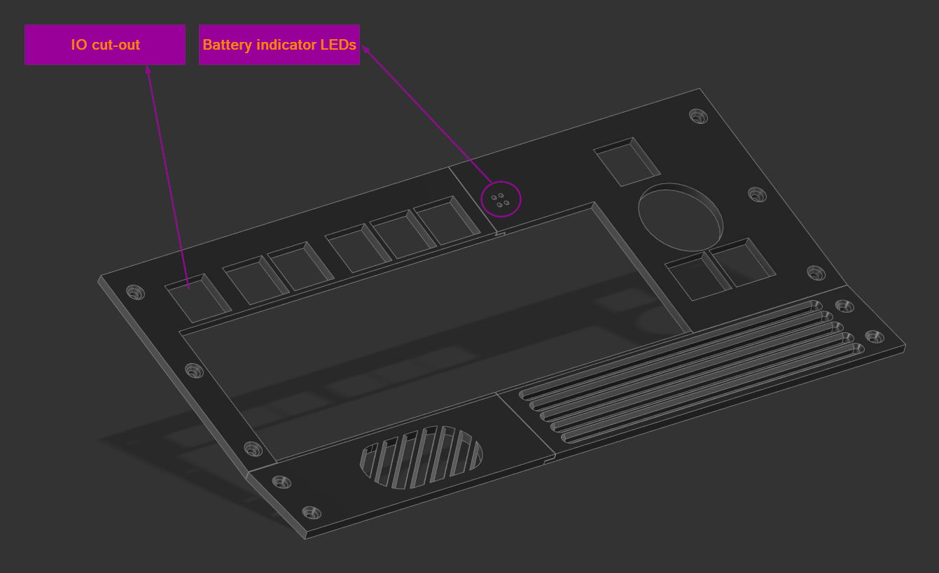
Here is the end result, and also the cutout labeling:
I also added double command for the track-ball buttons on the back side, I fill that sometimes, especially when you keep the deck on your lap it is easier to just move the track-ball with your finger and press the buttons from the back side with your index finger (especially when scrolling pages).
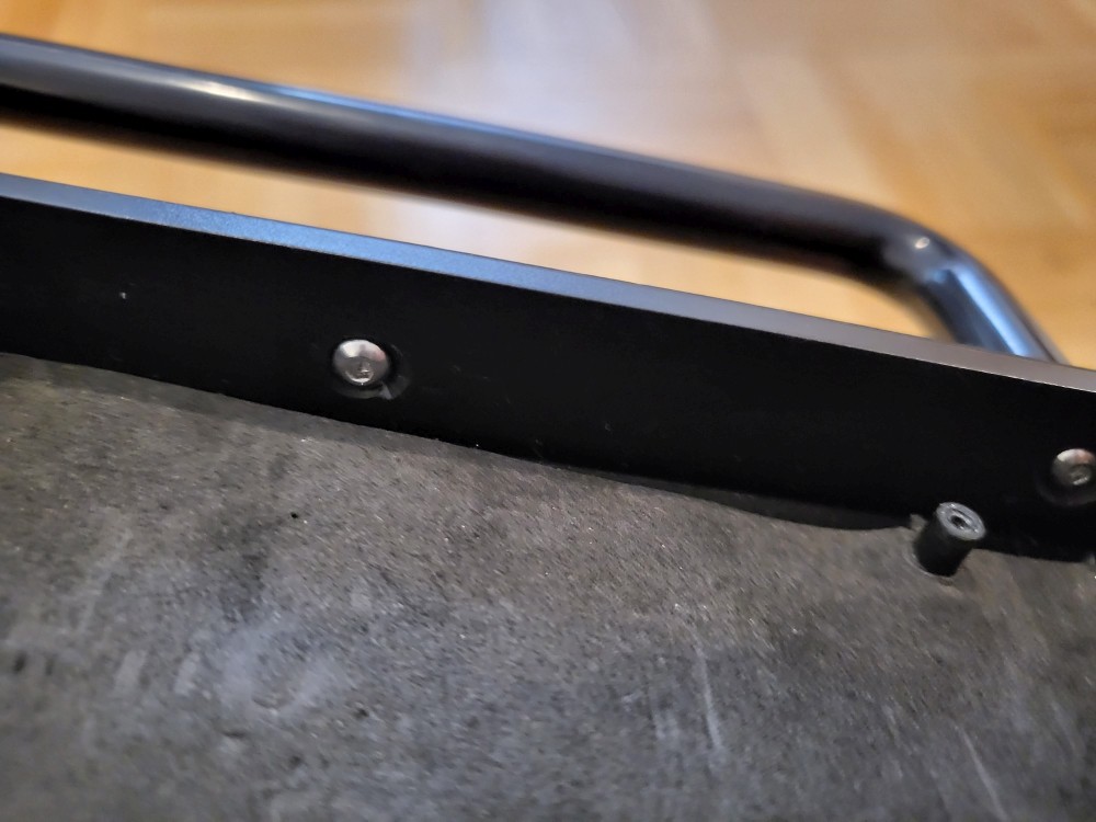
For the handler I just used a cheap plastic one from the general store and I also added some embedded nuts (since I bought like a 500 pieces set).
Face plate
For the face plate I initially intended to also add some 3w speakers with a cheap amplifier, but I later realized that because of all the connection wires (USB extender cables and the USB hub and switch) I had no room left for to fit the actual speakers. In my case, the speakers are not really high priority, but if this is important for your application, you might consider thinner cables, or to take out the 2to1 USB switch.
Since the face plate is in main view, it makes sense maybe to spend more time than me to polish and paint.
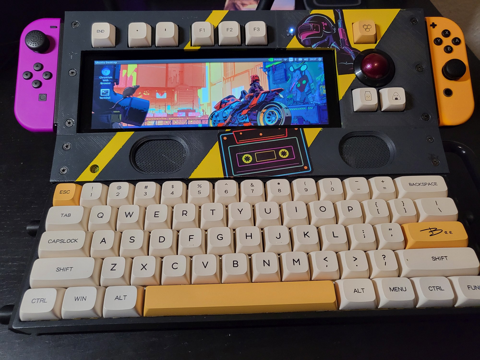
In my case, I was pretty impatient to put everything together, that I rushed the polishing part, and just thrown in some stipes and some stickers for some eye-candy :)
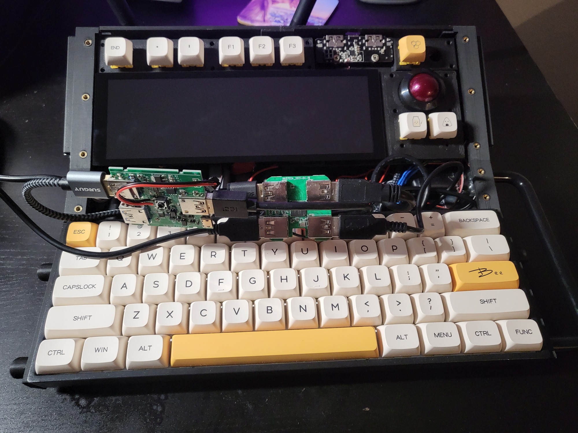
Before fitting the face plate, here are a couple of shots with the cable "management" and the connections of the USB Switch and USB Hub:

And here it is, a retro inspired cyberdeck, with Joy-con mounts (but to be honest, it looks a lot better with them unmounted) which can confidently run ROS/ROS2 for a quick hack of your robot. And having a mechanical keyboard for sure helps a lot with those long ROS terminal commands.
In the near future, I plan to release some short videos with the deck in action ;)
In case you are interested in an detailed assembly guide, let me know and I can make an update, even though I think if you check the 3d prints (and especially the fusion 360 assembly) you will get a pretty good idea how everything fits together.
Cheers!