 kelvinA
[17:00] You know those kinds of things that are simple and straightforward to do but don't do them because the idea of the process is kind of fuzzy? Yeah this test mount was like that.
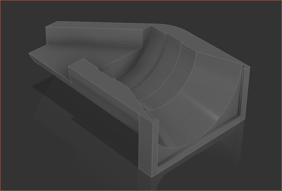 It took only 40 minutes of modelling and it's going to take another 42 mins to print the beam condensing side of the test setup. I lost (or likely didn't even save) the optical ray tracing setup I did in November so I had to use the screen snips provided in those previous logs to set up the model.
 Theoretically, what should happen is that I should be able to project an (IIRC) 9mm mirrored image of a screen at a wall and it will be the same size and sharpness at any distance.
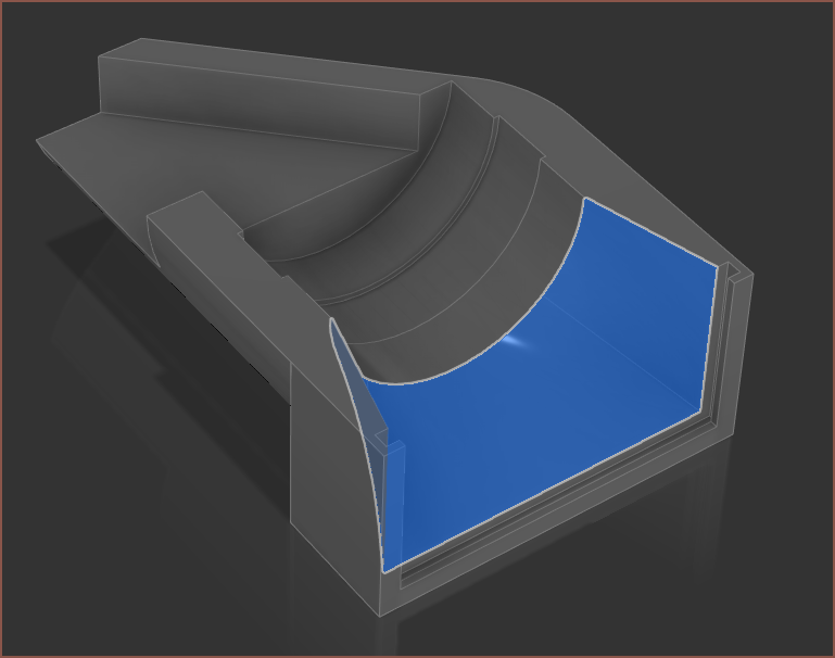
Oh just noticed a mistake. Fixed:
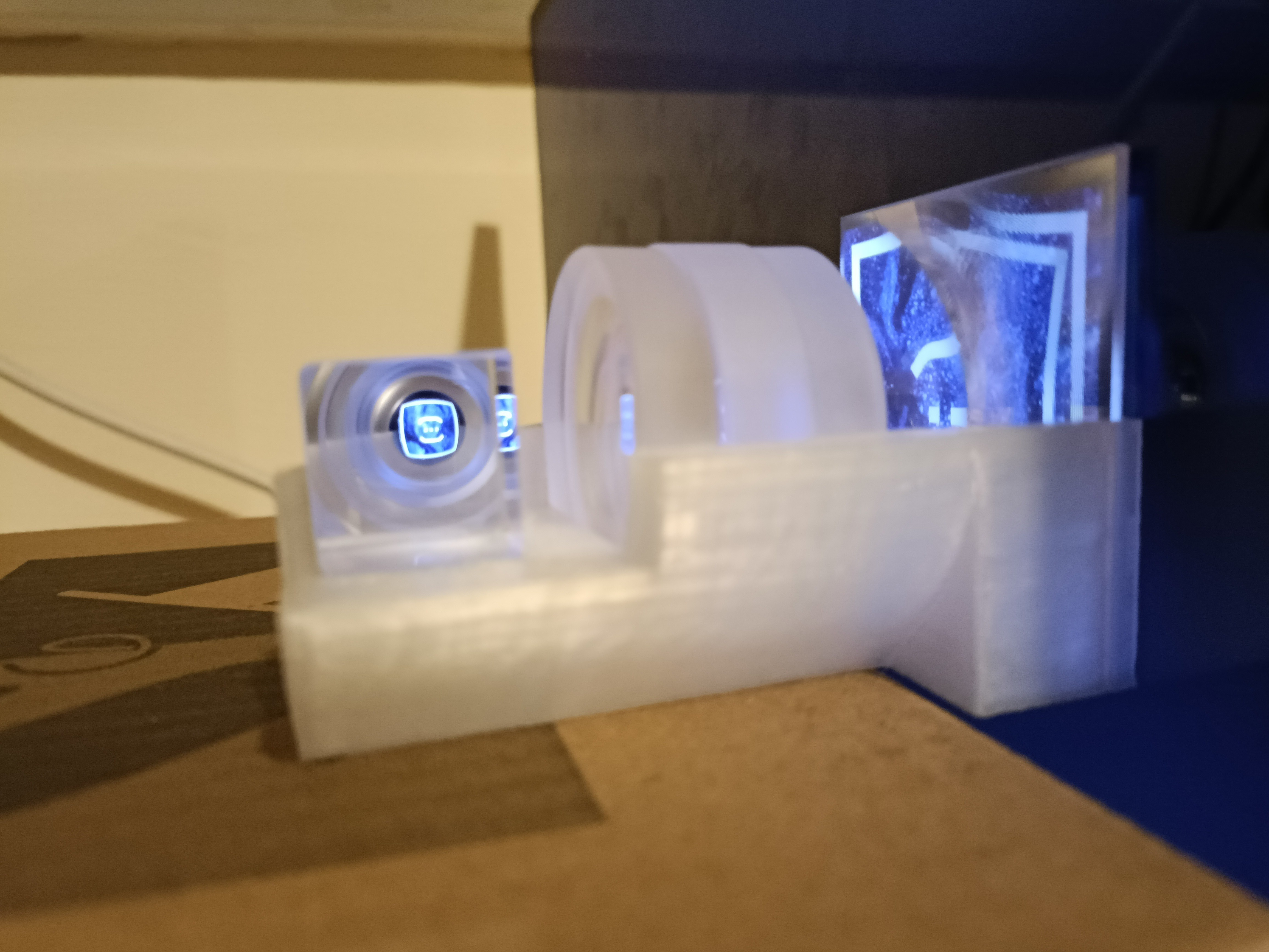
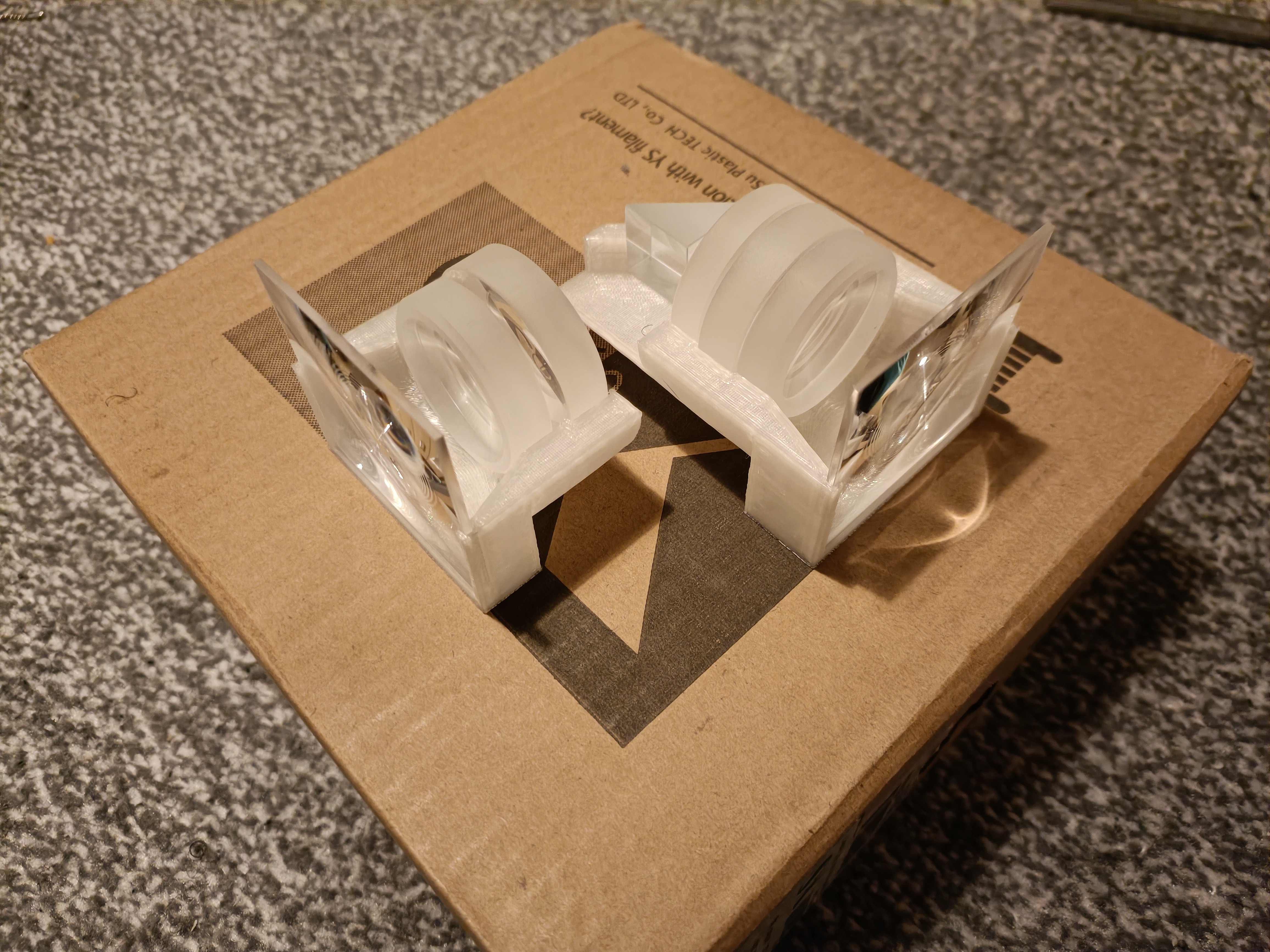
[19:00] So the print finished and the assembelled rig looks nice and exciting:
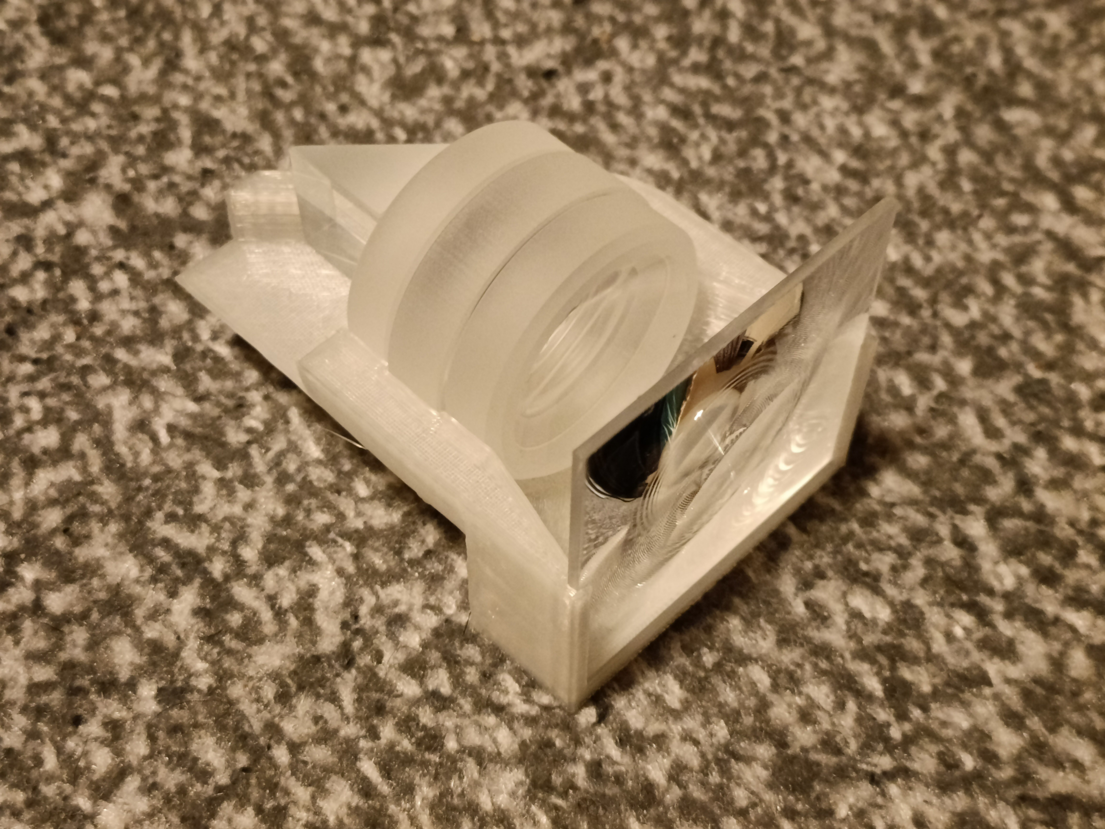 It looks really cool though the lenses (viewed where the 20mm prism is) but I didn't expect that all the visual area that wasn't the fresnel square would actually just be the walls of the other 3 lenses.
The middle of the image through the lens looks like it's at infinity but the sides of it doesn't. I think this is because I've dimensioned the space between the fresnel and the first lens from the closest side. This is not necessarily the same as the fresnel lens centre. For the decollimating optics, it should be correct, but for the above collimating optics, the dimension should've been on the outer side:
The edges of the square are also rounded. I was kind of expecting this since these aren't aspheric lenses. I'm hoping that the decollimating optics balance it out.
It does seem that the image is more or less the same brightness as the screen. I'm not sure if that's just my brain doing relevant optical processing on it though, as it does look slightly brighter in the photo.
Looks really cool in there, even if I didn't intend for the lens rings to be visible.
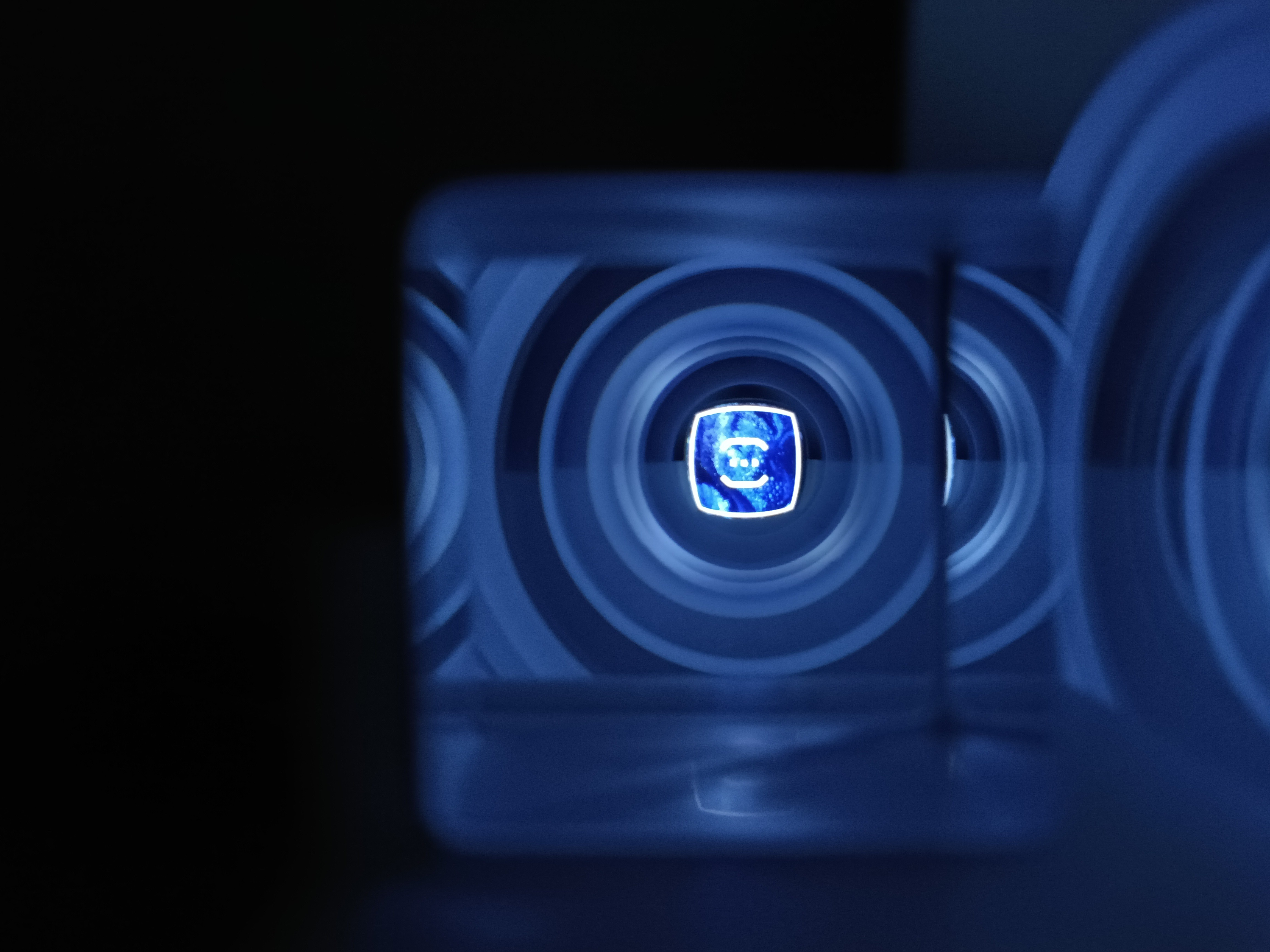
 This is the T.I.R. I was talking about in the previous log. I expect the beamsplitter to look somewhat similar. As said in a comment on that log, I'm going to try 30mm; I've printed the test cubes and placed them against my screen light protection (and very minor prescription) glasses, made a custom 2160x2160px resolution profile on my PC and moved in until the active area was in the bounds of the cubes. I put the distance into the calculator and I got 84.5PPD.
 Oh right that's 2160px not 2880px. I was wondering why the FOV decreased.
[19:40] The print for the decombiner is done.
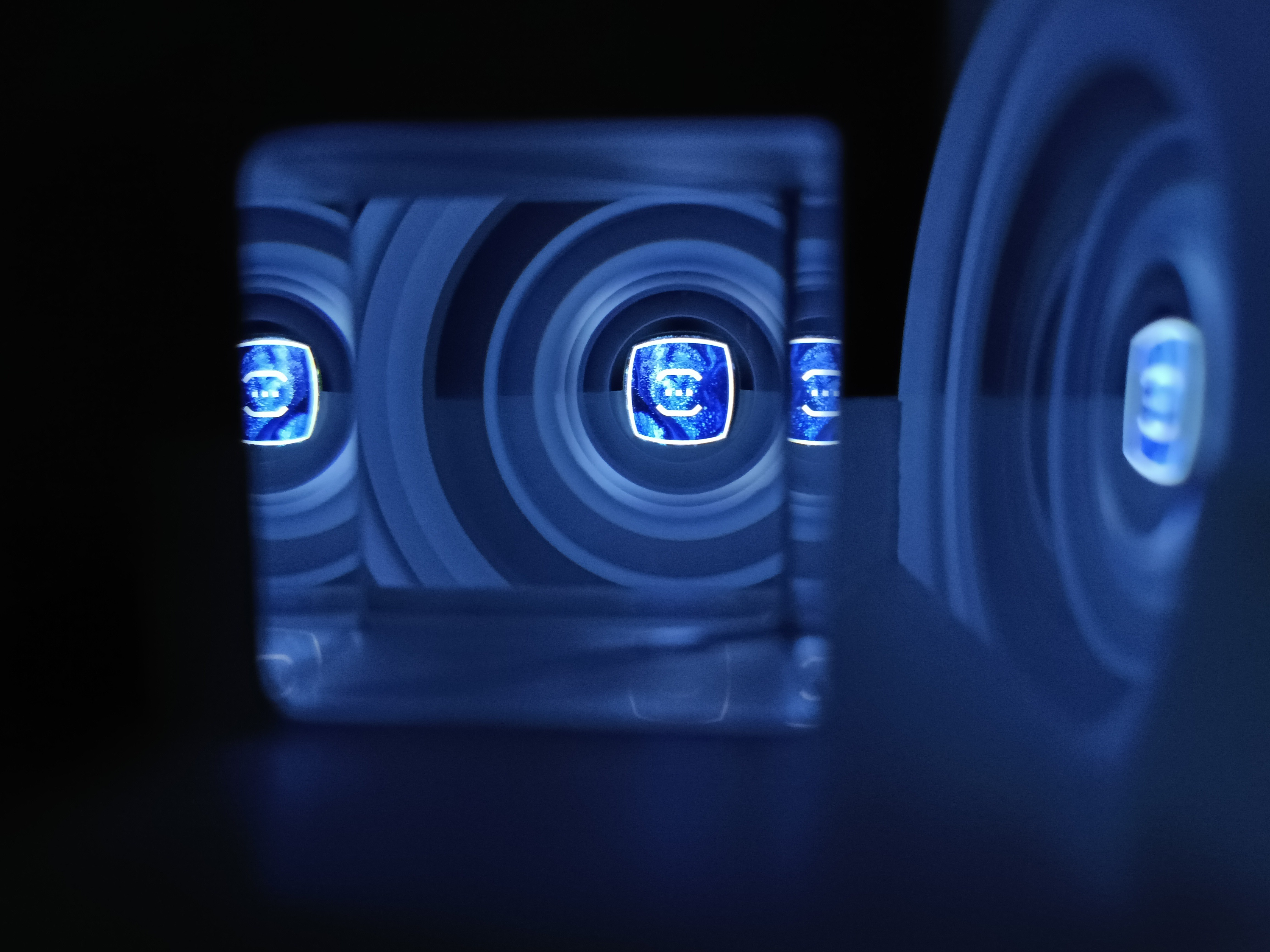
 The issue is that the view from the fresnel is wrong. What I'm supposed to see is like a seriously zoomed up image, but it looks more like a door lens (a.k.a. even smaller!):
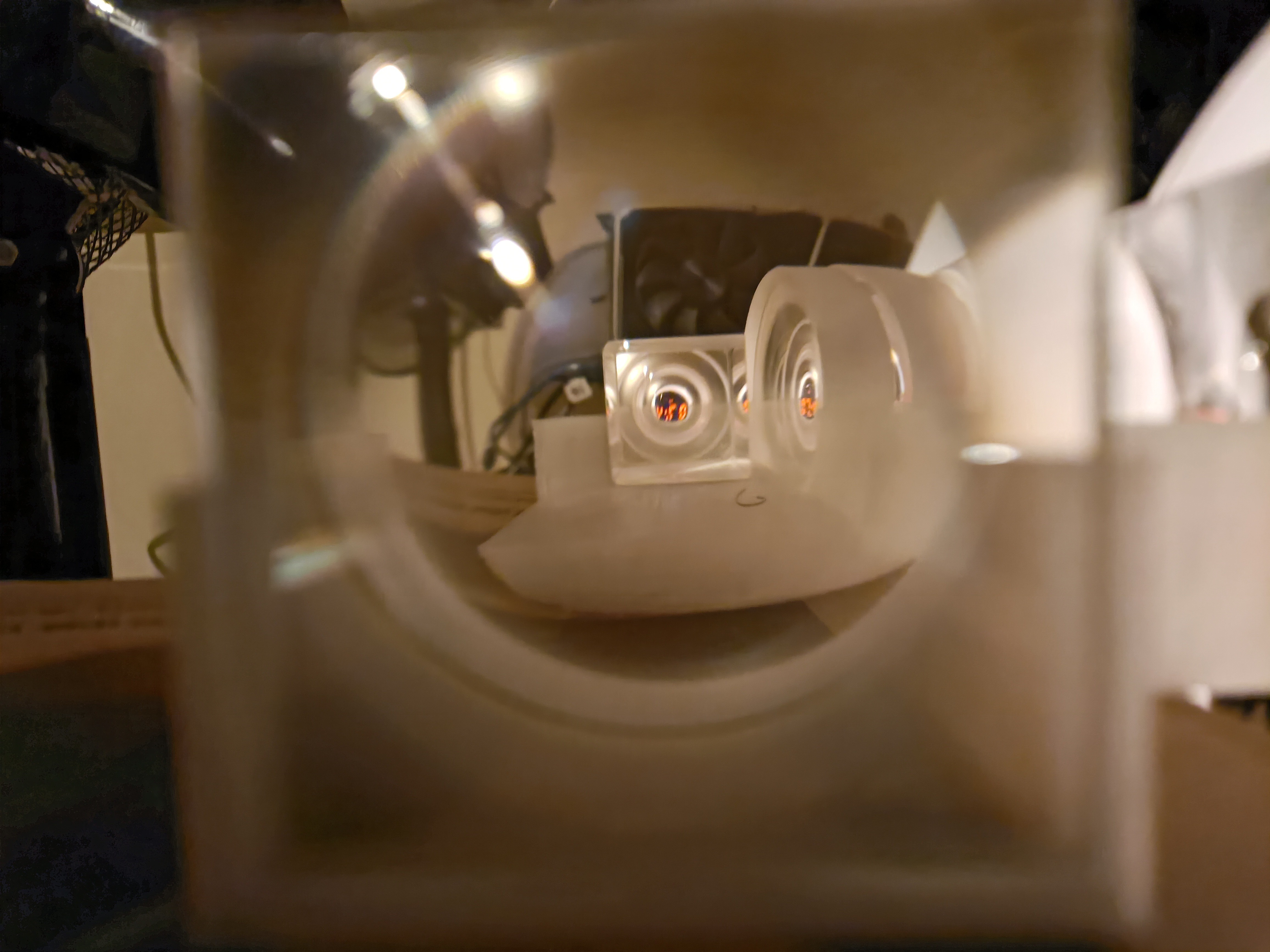 Unlike the collimator, it does seem like decollimator is more sensitive to lens distances.
In the calculator, I've got 25mm but in the sim it's 22. Could it be to do with that? I doubt it because I can move the lens outside to get that 25mm distance and it just makes everything blurier. Also moving my eye off axis makes things blurrier.
Moving the F-30 lens closer makes the image smaller fast. I tried just holding the lenses and moving them but it's nothing but a difference between complete blur and kinda blurry.
[The Next Day (23 Jan), 00:38]
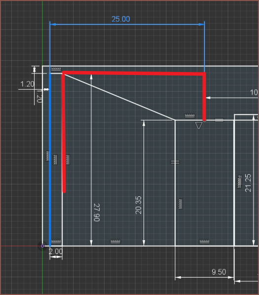
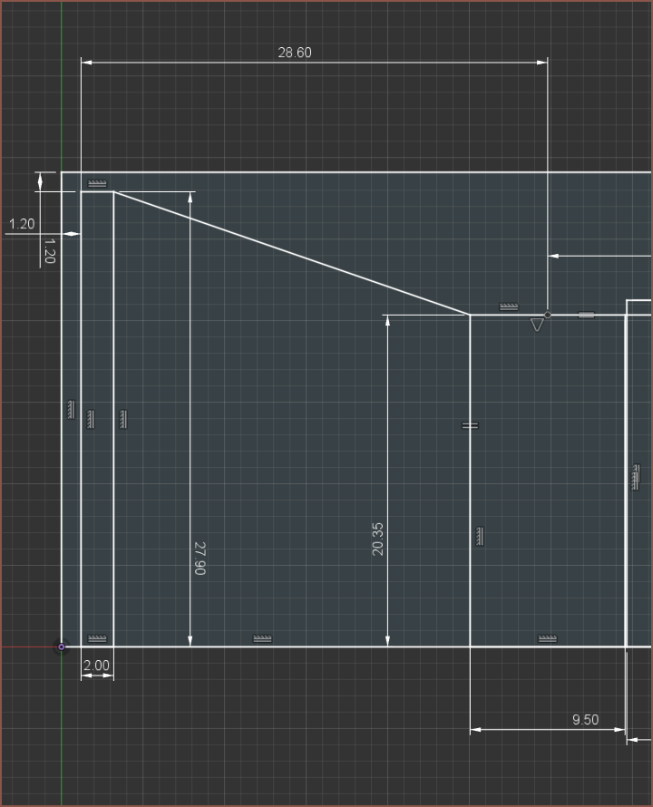
Ok I've got some good news. The fresnel for the collimator was actually really close to where it actually needs to be, accidentally. The image is inverted by about the same amount if the fresnel is outside its slot and pressed against the holder wall, which would be a displacement of 3.2mm. I've moved the mounting position +1.6mm of the original 27mm:
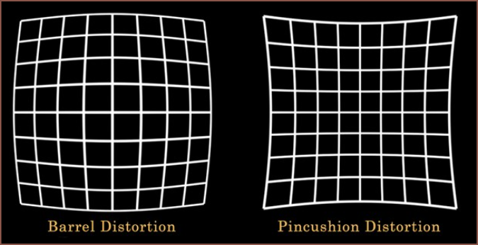
The bad news, as you may have already noticed, is that the resultant image is bent like a CRT monitor. That throws my image tiling strategy out of the window, even if the decollimator worked as intended. The official term is "barrel distortion" and if I had to pick one or the other, I'd go with this distortion.
Speaking of that decollimator, the 2 glass lenses just seem to make the image micro size. Trying to remember the virtual images of the simulation, I think that's supposed to happen so the simulation is seeming pretty accurate here. That means I've got to turn to the manufacturing.
I think the main issue is that spherical lenses are being used. Since even the edge of the fresnel lens is barrel-ified, I can only assume that it's the glassware doing this. That's a problem because it's not like I'm spoilt for choice in that department. Actually, now that I mention the distortion, it actually seems that the centre of the image at 27mm is at infinity but it's at 28.2mm where the edges of the image are approx infinity. I think fresnels are aspheric by default so maybe I can find some (or an AliExpress seller willing to make them).
Actually, scratch that idea because I just tried looking through the two fresnels I've got like a telescope and it's a blurry mess. Now I understand what that yellow website was saying about not using fresnels for imaging purposes. Man that's like going from Unreal Engine 4 OLED to PSP 3000 graphics! Nah the PSP had better graphics than that... The PSP 3000 graphics with a wrip + torn screen protector over it. The super crisp and clear image from a single fresnel essentially turns into this... scratched up and old plasticy looking image when doubling up. You can kinda already see what I'm talking about by looking at the orange digits in the decollimator image above. Why am I writing a description? Just taking an image would be better:
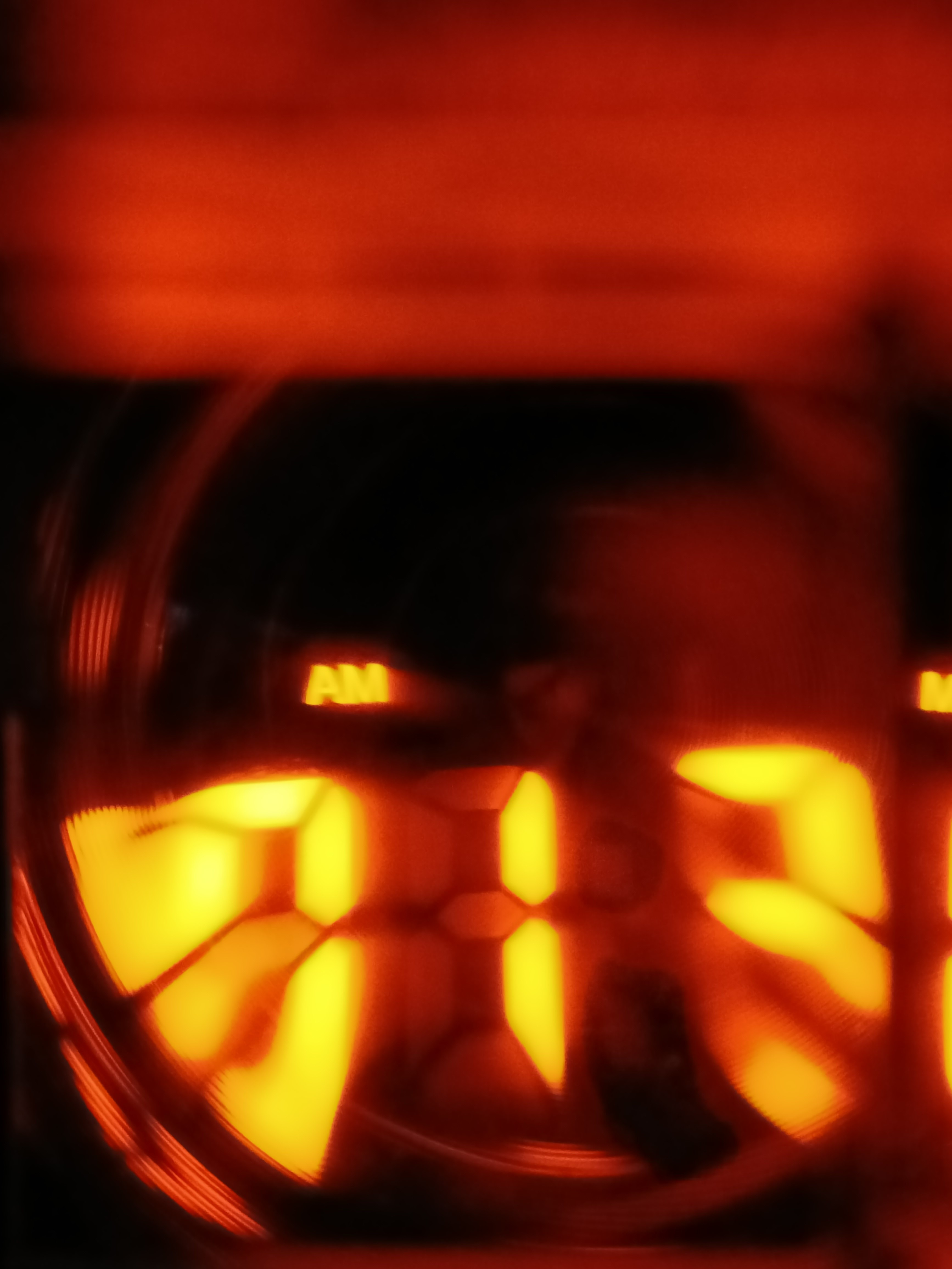 Here's the image (which I've flipped so that "AM" is the right way up).
Anyway, this also makes it seem that if I'm going to use fresnel lenses, there can only be one in the image pipeline or else I'd never get 20:15 (80ppd) clarity. With such limitations, it's sounding even more like I'd be going with this new beamsplitter cube strategy so that the decombiner can be a traditional (but hopefully square) lens. If I use the large combiner solution, I'd be limited to just the 2560px screen due to its physical size.
[02:04] Print just finished and still the same issue of the centre of the image being at infinity but the sides are only near infinity.
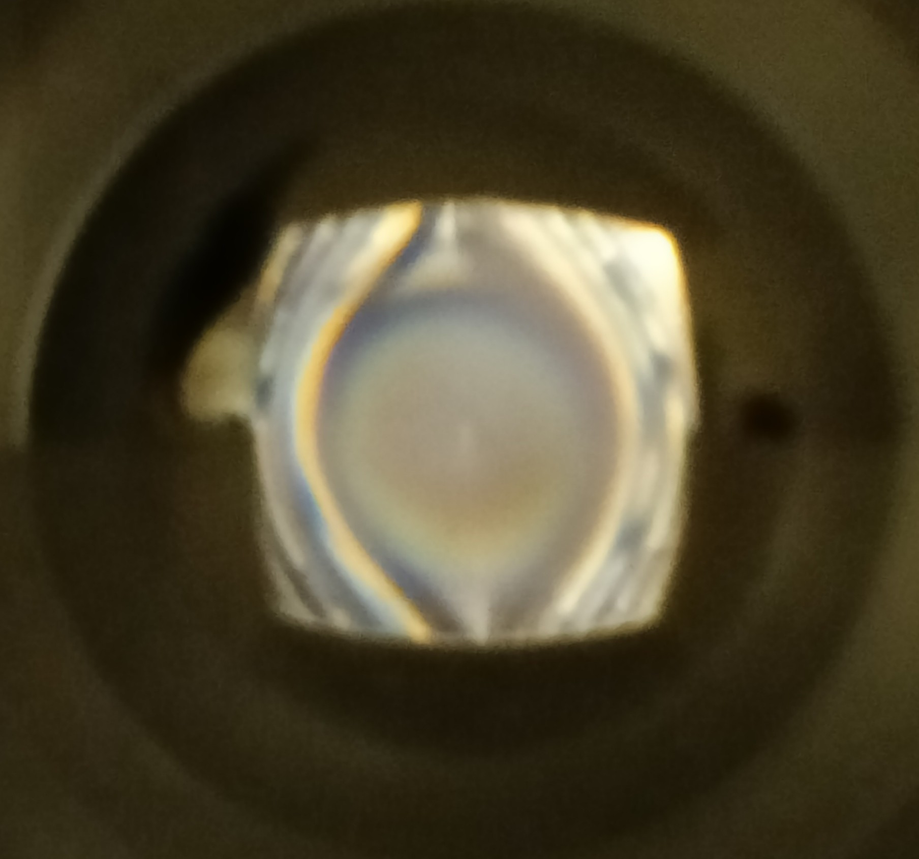 The whole thing is supposed to be a single-colour blur like the centre, without the side lines.
Discussions
Become a Hackaday.io Member
Create an account to leave a comment. Already have an account? Log In.
I screenshotted my desktop at 2160x1620px, mirrored it and then looked through the 20mm mirror prism (whilst keeping the other eye open for a fake transparency effect). Then I moved the screen distance so that I got a preferred screen and text size and put it into the PPD calculator. I got 32 degrees horizontal FOV and 66.7 PPD. Looking straight at the screen resulted in adjusting to a 77.1 PPD.
Thus, it seems my display shortlist is either the 2160^2 or 2560^2 displays. Honestly, the only con with the 2560 is the price.
Are you sure? yes | no