 BleakyTex
Booster v2.0
Even though the old booster is more efficient than those in most dosimeters on the market, it can be improved further. In fact, initially I chose the least elegant approach, just taking a conventional booster design and reducing its quiescent current through the use of low-power components and high-value resistors, but I made no architectural enhancements to it. The compact inductor I used wasn’t good for efficiency either. I was certain that there had to be a way to significantly lower the booster’s power consumption, yet I lacked any viable ideas.
Later I realized that the correct solution was to take the feedback from the transformer’s primary winding — the same principle as in photoflash chargers like LT3484. The main benefit of that method is that it doesn’t waste energy on the feedback at all as there is no divider at the output to drain the capacitor. The 1:12 transformer enables the use of transistors rated for lower voltages, as they have better characteristics than the high-voltage ones. Two ultrafast 1000V diodes and a 100nF 630V polypropylene film capacitor are used to minimize the HV leakage.
I also decided to use a different battery because LR44 batteries cannot deliver enough current for the new booster to work efficiently. Furthermore, with a larger battery and the more efficient booster there’s an opportunity to prolong the dosimeter’s single-charge lifespan for more (maybe a whole lot more, see below) than half a dozen years, eliminating the need for battery replacement entirely. I really wanted to use a battery with low self-discharge but they turned out to be unsuitable: Li-SOCl₂ batteries are dangerous and produce too much voltage to safely drive the LCD, Li-CFx batteries have too high ESR which increases even more at low temperatures. I went with a CR1/2AA 950 mAh Li-MnO₂ battery, as it can easily deliver sufficient current to the booster at a price of having higher self-discharge than the other two options, but not by much. With all those improvements the new booster consumes 0.56 µA at a normal background radiation level, quite a step up from 8.6 µA in the prior design.
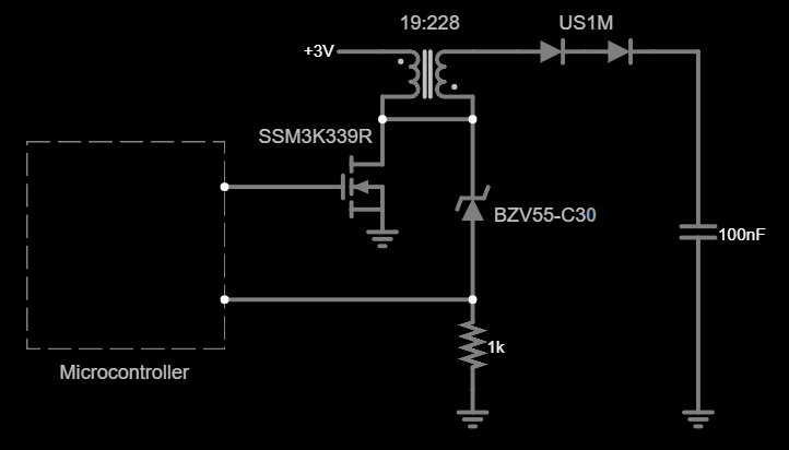
In retrospect, the solution to the problem of designing an efficient booster was right in front of me from the very beginning. While doing initial research I saw many articles mentioning the voltage waveform on the inductor; it’s a short pulse (VLXI) that begins when the transistor is closed, its amplitude equal to the output voltage if a regular inductor is used. If a transformer or an autotransformer is used, the pulse amplitude is divided by the transformer turns ratio (1:12 in our case).
The idea is to keep switching the transistor until the VLXI (kickback pulse of the primary) reaches roughly 400V / 12 = 33.3V. A 30V Zener is used to signal the microcontroller to turn off the booster when the VLXI had reached the desired voltage. I'm not sure why a 30V and not 33V Zener works, something is probably suppressing the peak of the kickback pulse but with a 30V Zener the booster stops when the output reaches 405V.
What’s left is to estimate when the dropping voltage in the output capacitor reaches a threshold value and then schedule a booster restart at the predicted moment. With this approach the output voltage is bound to fluctuate quite significantly because there is no way of knowing when exactly to recharge the capacitor since the voltage at the output cannot be measured without turning the booster on. Thankfully there is no need to keep the Geiger tube voltage at exactly 400V, since its minimum operating voltage is 380V, so just keeping it above 380V should be good enough.
Transformer design
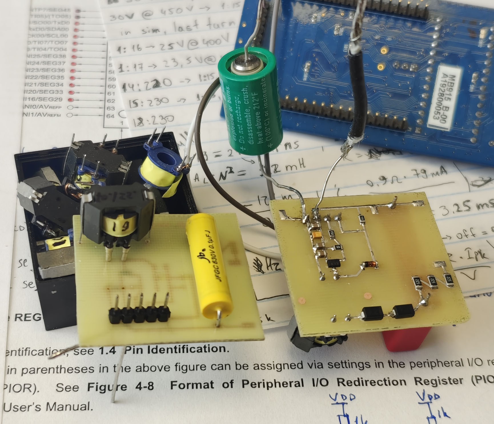
The rest of the circuit revolves around the transformer, so it’s gonna be the main focus of this post. I decided to use the RM5/I 3C90 gapless ferrite core because it’s the largest core that fits in the pen form-factor while having enough inductance per turn; high inductance is required since the microcontroller cannot switch the transistor on for less than 30.5 µS because it’s clocked by a 32.768 kHz crystal to keep the power consumption low.
The high-voltage transformer should be designed in a way that keeps the sum of all losses at a minimum. That includes:
- Resistive loss in the battery due to its ESR plus loss of its capacitance due to high current draw. This puts a limit on how high the primary current can be, effectively imposing a lower limit on its turn count. Also too few turns in primary will cause a core saturation as the primary with a small number of turns will have low inductance and thus the current through it will rise faster, and there’s a lower limit on the transistor on time as described above.
- Loss in the transistor.
High-voltage transistors have high RDS, Cout, and VGS(th), this puts a lower limit on the turns ratio as transistors rated for lower voltage have better characteristics — the lower the voltage the better. However, if the turns ratio is too high, the losses in secondary will increase. - Loss in the secondary.
The more turns the secondary has (high turn count in secondary means high turn ratio), the higher its parasitic capacitance, Cpar: in each operating cycle, the more Cpar × V²out / 2 of energy gets lost due to it, so less cycles means lower loss. This in turn sets an upper limit on the primary turns count which is inversely proportional to the current in primary, and thus the energy transferred per cycle.
The primary shouldn't saturate
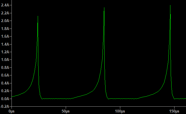
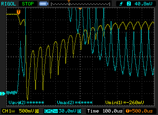
Initially I just wound a 10:150 transformer, expecting primary’s inductance to be 200 µH and thus a 450 mA peak current at 16.384 kHz 50% duty drive. The saturation current was calculated here and I’ve got 580 mA, so I wasn’t expecting the saturation to happen. I was using a 30V IRLML6346 transistor and a 1000 µF bypass capacitor to provide the energy for the transformer. The idea was to transfer as much energy per cycle as possible to minimize the CV² / 2 losses in the FET and secondary winding. The less cycles it takes to get from 0V to 400V, the lower the capacitive losses will be. Didn’t work all that well… When I powered the boost converter from the battery, it warmed up a bit. I’ve measured the current in primary winding and saw this:
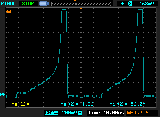
My tinyCurrent (clone of the uCurrent) couldn’t even show the whole picture as the inductor current was way above 1.5 A. Simple formulas for saturation don’t always work, apparently. After some time in Google I found out that LTspice is capable of simulating the non-linear behavior in inductors by using the Chan model, which is both accurate and easy to use. We need the following parameters for the simulation:
- Number of turns (N)
From the 3C90 material datasheet (magnetic properties):
- Coercive force (Hc), in Amp-turns/meter
- Residual flux density (Br), in Tesla
- Saturation flux density (Bs), in Tesla (must be taken from the table, not from B-H curve)
From the RM5/I core datasheet (geometric parameters):
- Magnetic length (Lm), in meters
- Length of the gap (Lg), in meters
- Cross-sectional area (A), in square meters
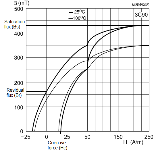
The coercive force Hc is the value of H when B = 0 at the bottom of the graph. The residual flux Br is the value of B when H = 0 at the left. The rest of the values are stated in the datasheet for the ferrite.
Here’s the LTspice simulation I used. Unfortunately, it cannot simulate transformers (coupled inductors) with this kind of model, so I’m just simulating the primary winding here. The number of turns is 9.6 instead of 10 because the last turn is not a full turn as the wire has to be routed to the bobbin’s pin halfway in.
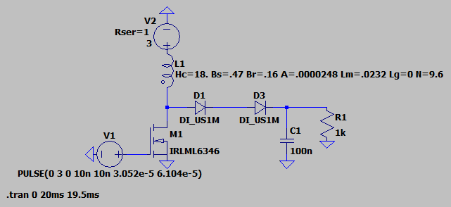
Looks pretty close to what I got in practice. After some poking around I found out that 19 turns in primary creates the best balance between the peak current, the transistor voltage, and the number of secondary turns. The final version of the transformer has 19 turns in primary and 228 turns in secondary. I went with a 1:12 turns ratio because it allows me to use a FET with low enough voltage rating, without needing too many turns in secondary at the same time. At 400V output and 3V supply such a transformer will produce a 3 + (400 / 12) = 36V kickback pulse. The transistor should be able to withstand this voltage. Transistors rated for higher than 45V have suboptimal RDS, output capacitance, and gate threshold for the task. I’m using an SSM3K339R FET, it’s rated for 40V.
Let’s simulate this transformer coupled with the new transistor and check how well the simulation fits the experimental results.
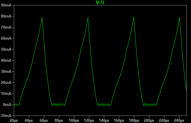
Would you look at that, the peak current is 78.9 mA in simulation and 78.4 mA in practice. The average current is 18.2 mA which is optimal for the Li-MnO₂ battery; it shouldn’t lose its capacity due to high current draw.
Discharge time matters too
While on the oscillogram above the inductor current has a rather nice waveform, it’s not always like that. With the 16.384 kHz 50% duty drive, when the boost converter begins the charging cycle and the voltage in the output capacitor is near zero, the transformer won’t have enough time to transfer all of its stored energy into the capacitor, and that in turn will increase the current in primary, overloading the battery:
Note: the current doesn’t drop to zero anymore because I connected four 10uF 16V X5R capacitors in parallel with the battery to reduce its peak load. This reduces the resistive loss due to the battery’s ESR, and also prolongs the battery life since high loads reduce battery’s effective capacity. Such capacitor configuration is used to achieve lower leakage through them, which was 5 nA in my case. There’s a good appnote from SiLabs on this topic.
It’s easy to show that the transformer discharge time depends on the voltage at the output capacitor by deriving the time from the well-known formula for the charging inductor current:
The discharge inductance in case of an autotransformer is the sum of inductances in primary and secondary:
Ldis = 122 mH
Same for the winding resistance, which is a sum of resistances in primary and secondary:
Rdis = 26.3 Ω
Ipk = 78.4 mA, as measured on the oscillogram above.
The initial voltage in the output capacitor equals the 3V supply. Plugging the numbers in shows that the transformer takes 5.5 ms to fully discharge when Vout is 3V, but when it gets to 50V the discharge time shall drop to 0.2 ms.
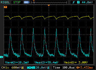
I didn't do the numbers when I was experimenting, I just intuitively set the PWM output to 6.5 kHz, 20% duty (30 µs charge time, 0.12 ms discharge time) and this almost eliminated the current spike:
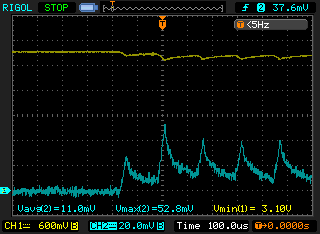
The battery easily handles a single 52.8 mA pulse, never dropping from its resting voltage in full. There’s still some room for improvement but that’s a story for another time.
As for the booster restart delay estimation, I’m not sure yet on the exact algorithm. The measurements tell that, even though the tube consumption is easy to measure by just counting its pulses, the capacitor leakage is bound to fluctuate depending on the environmental conditions such as temperature and humidity, so the algorithm will have to estimate that leakage on each recharge cycle.
Winding technique for the lowest losses
The parasitic capacitance in the secondary winding causes significant losses, so the transformer must be wound in such a way that reduces it. I’m using two methods described here (explained in more detail here).
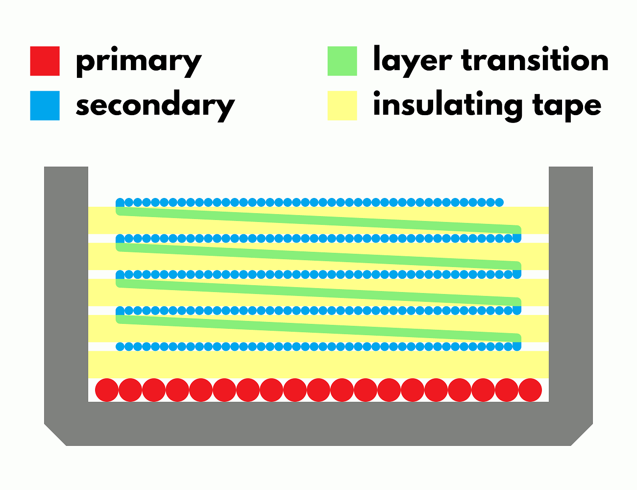
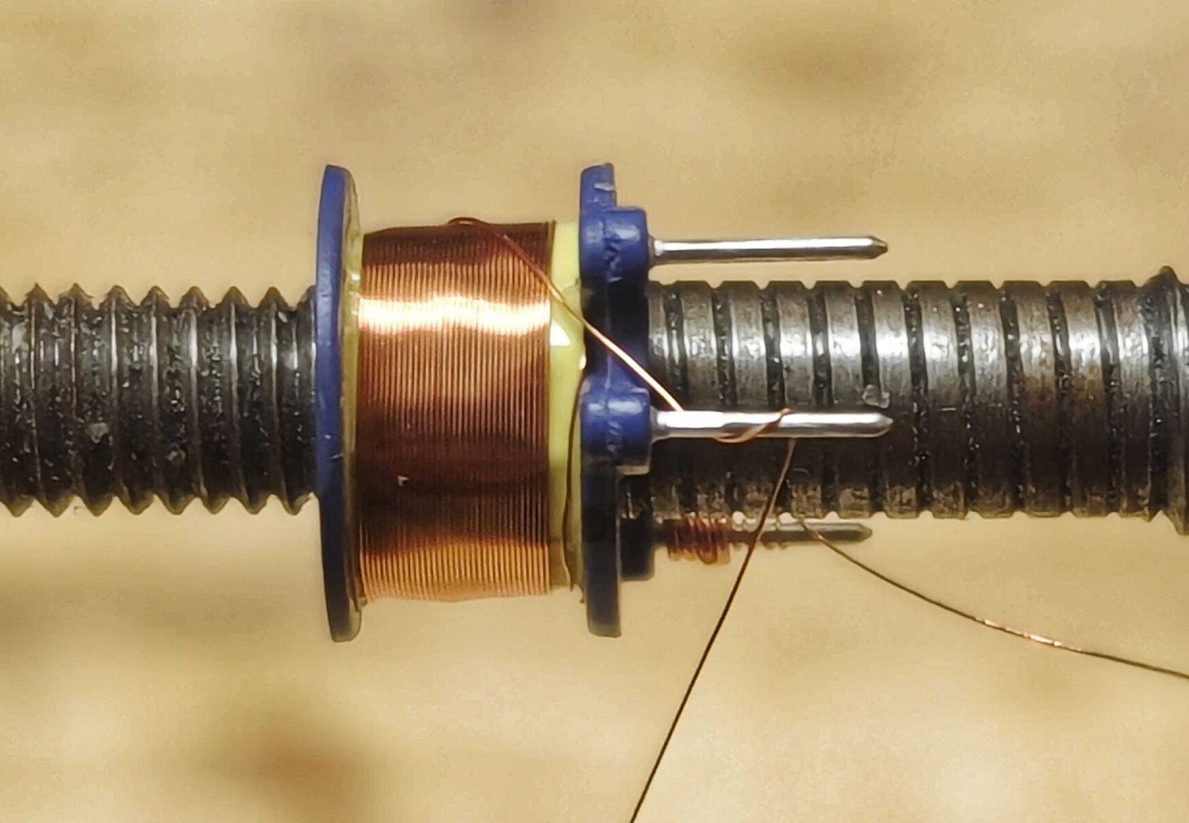
Each winding layer has to be separated from its adjacent layers with insulating tape to increase the distance between them, this is the first step to reduce the stray capacitance. The primary (0.224 mm wire, 19 turns) is wound in one layer at the bottom of the bobbin, the secondary (0.07 mm wire, 228 turns) is wound in 5 layers of 46 turns. All layers of wire start at the same edge of the bobbin. When layers are wound starting from edges opposite to one another the capacitance is at its highest: if the first turn of the previous layer is opposite to the last turn of the next, there’s twice the voltage per layer between those turns. As the energy stored in the self-capacitance is proportional to voltage squared, this more than offsets the lower voltage difference at the other side of the winding. Lower capacitance can be achieved by winding each layer in the same direction, with a section of wire in between layers to return to the other edge, so the wire is wound right to left, then right to left again on the next layer, see the photo below. That way the voltage between layers becomes uniform.
All those measures described above increase the conversion efficiency by 17%, resulting in a total efficiency of 65% at 3V input and 400V output, which is comparable to the commercial solutions.
Revisiting the tube consumption
In the first log I estimated the tube consumption using a rule-of-thumb formula, but never got to test the numbers in practice. But first I need to check how much energy is being lost in the booster’s capacitor and the output diodes.
I connected a voltmeter with >1011 Ω input resistance to the HV capacitor and started the booster that charged the capacitor to 400V and turned off. The voltage has dropped by 7V in 10 minutes, which is 0.0117 V/s; linear approximation is fine at such a small voltage drop.
Since the current is the amount of charge transferred per unit time, the leakage current can be calculated using the formula for the charge stored in a capacitor:
Then the battery consumption due to the HV leakage is:
While the booster’s efficiency in charging the capacitor from 0V to 400V is 65%, it drops to 53% when recharging the capacitor from 380V to 400V, so I used 53%.
Got the estimate for the leakage, now let’s see how much current the tube is consuming. I charged the capacitor to 400V and connected an M4011 tube to it. I decided to ditch the SBM-20 because M4011’s intrinsic noise is 5 times lower compared to SBM-20 and the sensitivity is pretty much the same. Then I placed a radioactive source near the tube and the voltage dropped by 10V in 11 seconds, so the impact of leakage (0.0117 V/s) on the measurement is negligible. The tube has produced 299 pulses over that period.
The total charge the capacitor lost is as follows:
So, a single pulse consumes:
The rule-of-thumb formula gives 1.6-ish nC. Good enough for me, at least it’s correct within an order of magnitude.
Given that the tube has 400V applied to its anode and, under normal background radiation, produces 0.33 pulses per second consuming 3.3 nC per pulse, its power consumption is:
Given the 3V supply voltage, the tube's battery consumption is:
The total consumption of the booster, driving the M4011 tube exposed to normal background radiation is 550 nA. Looks good so far, though I want to try and reduce the leakage even more. VS-E7MH0112-M3 diodes, for example, should leak even less than US1M’s.
A new microcontroller
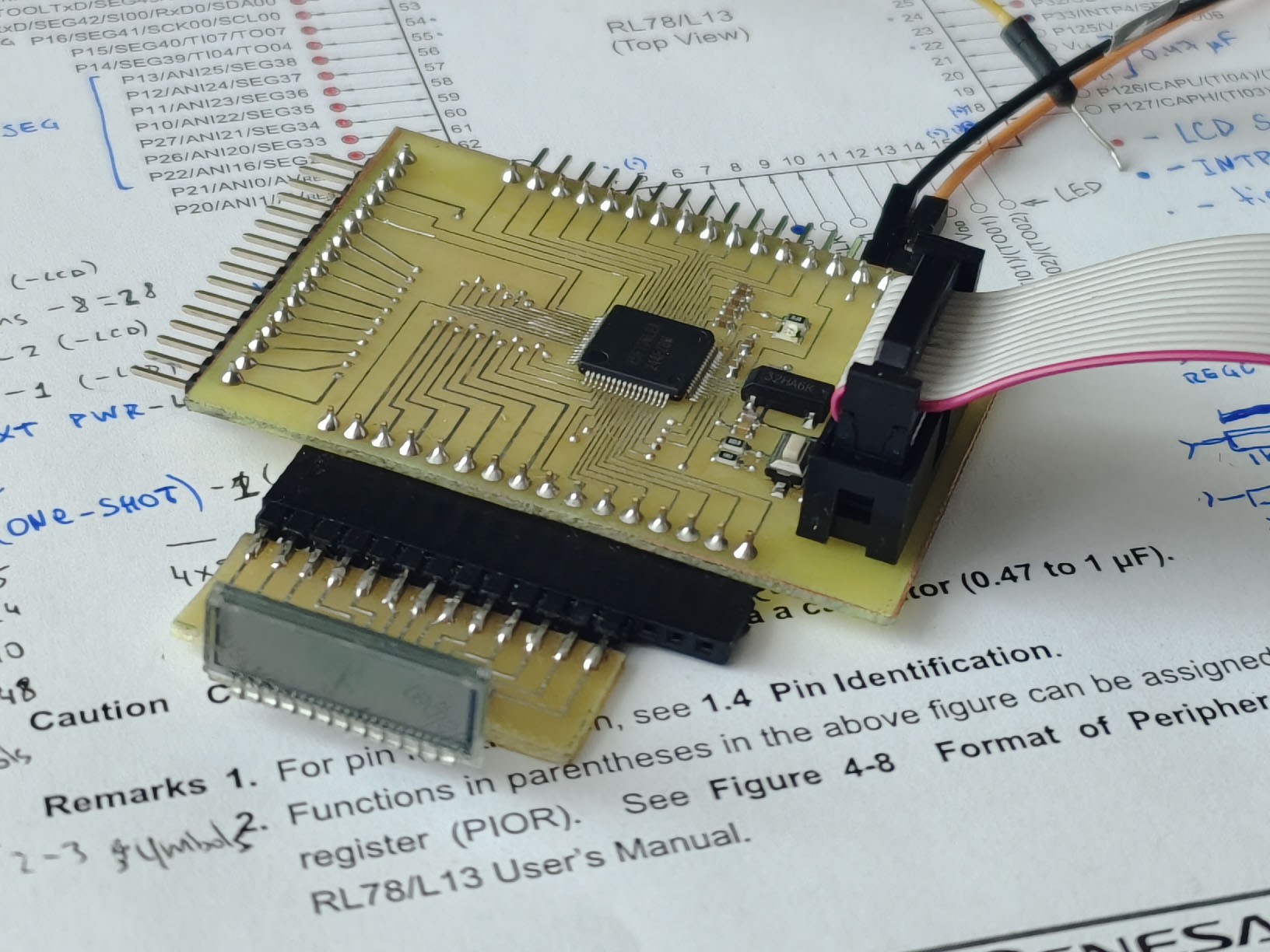
Long after I made the first revision of this Geiger counter, I noticed that the entire STM8 product line was going to be discontinued (late update: not anymore, but the damage has already been done). That, combined with the new booster design requiring neither a comparator nor a voltage reference, made me reconsider my choice of the microcontroller. And I did find a much better one. Behold, the RL78/L13 series from Renesas. There is also the L12 series which consumes slightly less but it also has less flash memory capacity, and I want a lot of it for the measurement logs. I got an R5F10WLEA and made a breakout board for it to see what it’s capable of:
Since the microcontroller is going to spend most of the time in sleep mode, with just the RTC and the LCD controller running, consumption while sleeping matters the most and, according to my measurements, the RL78 chip only draws 0.5 µA. The STM8L was drawing 2.4 µA in the same mode. Also there’s no need to run the code from RAM this time, since RL78 is consuming 4.1 µA while executing from flash; STM8L consumes 5.5 µA executing from RAM with flash disabled. Since the core is active for less than 0.75% of the time (<15 ms every 2 seconds), it contributes less than 31 nA to the total consumption.
The microcontroller consumes 0.53 µA, the booster consumes 0.55 µA, the battery self discharge current is 1 µA (1% of capacitance per year), so the total consumption is 2.1 µA. Considering that the circuit can utilize up to 90% of the battery, the effective capacitance of a 950-mAh Li-MnO₂ battery is 855 mAh. With 2.1 µA consumption from a 855-mAh battery the device can, in theory, last for 46 years. Impressive, huh?
Of course it won’t last that long in the real world, although at this point the main limiting factor is not even the device itself but the self-discharge of the battery, and it can vary a lot. I need more experiments to confirm that those numbers are true, but even if they’re worse by a decimal order of magnitude, which they most likely aren’t, the new dosimeter design is going to last multiple years from a single CR1/2AA cell.
Discussions
Become a Hackaday.io Member
Create an account to leave a comment. Already have an account? Log In.
Holy hell this looks awesome! Great job!
Are you sure? yes | no