 thesebelik
10/06/22 update: I didn't provide enough details on this project before, so I'm editing this for clarity and to cover a lot more specifics.
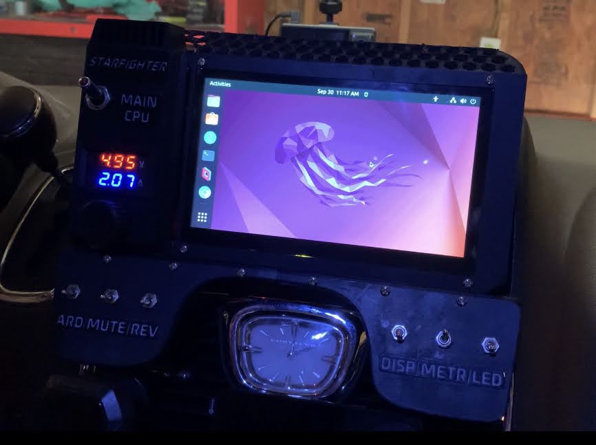
It turns on!!!
My car is very special to me, and I spend a lot of time driving it, but the one issue that always has bothered me is that the factory radio simply isn't good. I would mainly use it for its bluetooth functionality and stream music from my phone, which gave me the most control over what it is that I'm listening to. That bluetooth functionality worked, but like, barely. It was aggravating to use and basic functions like pairing a new device were unreasonably difficult. So, around the end of 2021, I started brainstorming ideas for my own custom radio/head unit replacement!
Here were the design considerations that I landed on: I wanted to ditch the bluetooth entirely, all music should either be streamed or saved locally. It should also retain 100% functionality if my phone dies or gets left at home or whatever. It should be relatively easy to use, even for someone who's never seen it before, and obviously shouldn't be distracting or dangerous while driving. That being said though, it would be pretty sick to be able to watch youtube or something while, say, waiting in a drive thru line. I also desired built in GPS functionality and, if possible, access to the backup camera feed at any time (still working on that one).
Starfighter as of 10/06/22.
Disclaimer: Starfighter is definitely still incomplete. I was only able to get so much of it done before the contest deadline, so I worked to get all of the parts from CAD printed out and do some basic wiring to submit what I had, but I'm going to keep working on it. I'll update this page as I go along. For now though, I'll outline what has been done and what is planned for the future.
So, as it stands right now, Starfighter is an Atomic Pi (more on that later) x86 single-board computer powered by a 75W DC-DC converter to regulate the 12-14V of my car battery down to 5V. I've experimented with different linux distros to run on it and right now it runs ubuntu with a couple basic modifications, although I think I'm still going to change this later. The OS runs on the Atomic Pi's internal eMMC, but that's only 16GB so I've also plugged in a 128GB micro SD card. I may upgrade to a real SSD later if speed or reliability becomes an issue. Internet connectivity is handled by a portable 5G hotpot that is connected via ethernet, and it is usually pretty speedy. The main interface is a 7" Uctronics touch display connected via HDMI. In my current setup that display needs two micro USB connections, one for power and one for touch controls. The Atomic Pi has a USB port deficiency, so those two connections come from a 4-port powered USB 3.0 hub connected to the Pi's single USB 3.0 port. Also connected to that hub is the dongle for a small wireless keyboard/trackpad combo that has been waiting for years in my junk drawer for a project like this. I have a rotary encoder and knob for volume control, but that's not hooked up yet. You'll notice that Starfighter has a number of toggle switches placed around the front panel, and while most of them don't do anything just yet, I have wired two of them up. The "MAIN CPU" switch of course turns on the Atomic Pi, while the "METR" switch near the bottom right toggles power to a cheap power meter that I found on Amazon. It's been wired to display the voltage as well as current flowing through my "main power bus".
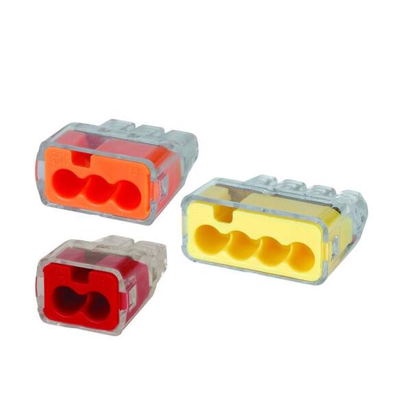
Precise power distribution is an important part of this project, and while I'm no electronics expert I think I came up with an interesting solution. If I were to do purely point-to point wiring with soldered connections, in some places I would end up with like 6-8 wires all terminating at the same place. That didn't seem like a good solution, so instead I picked up a couple packs of these wiring connectors from Home Depot for a couple bucks. I used the 4-port ones the most, and if I need to connect more than 4 wires together I can just chain two of them together!
I'll talk about all the 3D printed stuff next. These designs are also not quite done, but pretty close. I've put up all my STLs as well as my main SLDASM file in the project files. Designing and printing these parts has definitely been the most time consuming part so far, but I'm pretty proud of the results.
From my initial tests, I knew PLA wasn't going to cut it. It would be okay for a little while, but I experienced firsthand with one of my prototype designs exactly how PLA will just melt when you leave it in a hot car in the summer. So, I knew I would have to print all my finished pieces in ABS. It wasn't until after I had purchased a roll of ABS filament that I learned about ASA, so that'll have to be a learning experience for another time. As many of you who have printed in ABS will know, getting it to not warp right on the print bed is its own challenge, but I eventually conquered it and after playing with the Z-offset I was actually able to get an extremely smooth finish that I'm quite proud of on the bottom side where the part adhered to the print bed. It almost looks and feels injection molded! I took advantage of this when designing the parts to be printed, so all of the front facing panels were printed flat with the front side touching the bed and got that nice smooth finish. No post processing necessary!
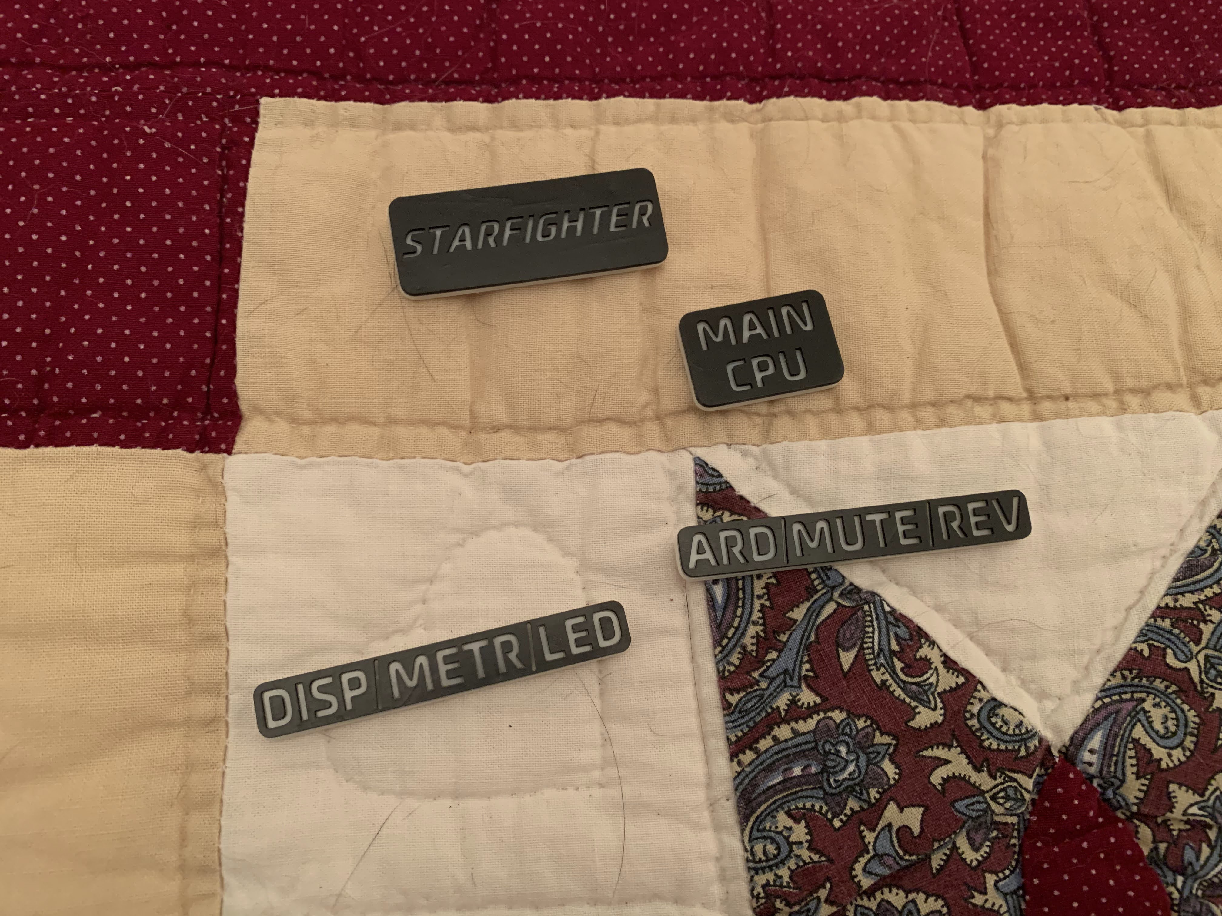
I wanted to show off my resin printing skillz too, so all the parts with text as well as the volume knob were printed on my Elegoo Saturn. I modelled them separately, while including cutouts where they were meant to go on the main model. I did the text panels in a two color process that I had never tried before, where basically I started printing the bottom part in white resin but paused the print exactly at the right layer to clean the tank and pour in some black resin to finish. The end result is a plate that is basically a solid white rectangle on bottom, but on top it's black with the text cut out of it. I'm super happy with how they turned out, and while I don't have a picture right now I can tell you they look super sick with the LED backlighting that I have planned.
Okay, let's talk future plans. Obviously all the switches will have functionality eventually, so I'll start with those:
ARD- Toggles power to Arduino Nano (more on that in a sec).
MUTE- Self explanatory. Cuts power to the Atomic Pi's amplifier, so it can't even generate sound.
REV- Not fully fleshed out yet, but will actuate a cheap HDMI switch I found at Walmart to toggle between the input from the Atomic Pi and the feed from my backup camera, using an analog to digital converter that I also found at Walmart. The signal from my car's factory backup camera is analog, but I haven' tested whether or not this converter can actually make sense of it. I also think I might have to use the Arduino to flash an IR LED at the HDMI switch to emulate channel switch commands from the IR based remote that came with it.
DISP- Toggles power to the main display.
METR- Hey, this one works! Turns the power meter on and off.
LED- I have a Neopixel RGB LED strip that makes this winding, serpentine path throughout basically the whole build. It will provide backlighting to all the panels with text for visibility at night, as well as shine up through the vents at the very top for a cool scifi glow effect. Everything from the future glows blue, right? This switch turns the LED strip on and off.
Now, let's talk about that Arduino Nano. It's easily the biggest unknown of this whole thing, because I haven't even started writing the program. Heck, I barely know the language! I only have a little bit of prior experience programming for an Arduino, and at that time I was using Matlab! I don't have access to Matlab anymore though so I'm using the real deal Arduino IDE for this one.
I have wound up with quite a stack of functions that this little guy has got to do. The only reason I have an Arduino in here at all to solve one basic problem: the Atomic Pi starts up too slow. If I'm in a hurry, I want to be able to turn my car on, throw it into reverse, and I expect to be able to see the feed from my backup camera on the screen almost immediately. To solve this problem I knew I would need an HDMI switch, and I would need to actuate it somehow without relying on the Atomic Pi (which can take over a minute to boot up). I've built in a manual toggle switch to do this, but I wanted an automated solution as well. The "enchilada" breakout board that I got with my Atomic Pi has a spot built into it to slot an Arduino Nano, so I figured I would go with that. Of course, the list of things that I want to start up fast ballooned, as well as the list of things that I thought would be easier to program into an Arduino than some process running in my main OS. Right now, the Arduino Nano has on its to-do list: HDMI switching logic, driving the Neopixel strip, reading the rotary encoder and forwarding "volume up", "pause", etc to the Pi, and then worst of all: CAN bus integration!
I knew from my initial testing that I was going to have to talk to my car's CAN bus at least a little bit. You see, my car has this really weird thing where if you disconnect the factory radio/head unit from the bus, the blind spot detection system completely stops working! I have tested this phenomenon a good deal, but still have no idea why this is the way that it is. The blind spot system stops working whether the radio is disconnected from the bus entirely, or if power is cut to the radio by removing the fuse. However, if you reconnect the radio to the bus, even if it's in a completely different physical location (I tested with the CAN wires that normally go to the front passenger seat), the blind spot system works just fine again! This means to me that there has to be some kind of communication between the blind spot system and the radio, but I cannot fathom what that would be. I've done a wee bit of sniffing on the bus, and there are ~6 new messages that get sent over the bus when the radio is connected vs disconnected, but I've really only barely started the process of decoding the meaning of any messaging on the bus. I'm definitely in a little over my head with this one, so if you have any insights on to what the heck the radio and the blind spot system could be talking to each other about, please let me know.
So anyway, I purchased a MCP2515 chip to translate between CAN bus and Arduino, and while I've got it working well enough to read and send messages on the bus I don't have any final functionality implemented. Aside from emulating that weird radio-blind spot communication, such functionality would probably include reading things like steering wheel media controls or what gear I'm in, dimming the Neopixels based on the value of an inbuilt dimmer switch that controls other lights built into my car, and maybe some other extraneous things like controlling the windows and A/C and stuff. I've also toyed with the idea of having the screen function as a second digital dashboard, displaying things like speed and RPM in a cool, cyberpunk-y format. (something like this: https://www.reddit.com/r/Cyberpunk/comments/x4c5vr/made_some_edits_to_my_digidash/) That kind of stuff would have to run on the Atomic Pi though, which would involve somehow getting the MCP2515 data to both the Arduino and the Pi.
So, that's the Arduino side of things. I have no idea how much of this I will actually be able to fit/run on that little Nano, so we'll see how many "alternate solutions" (read: janky hacks) I'll have to resort to in the end.
I suppose I should also mention GPS, as I have purchased a GPS chip but I haven't been able to make it talk to the Atomic Pi just yet. I was trying to connect it over UART, which was a little tricky given my current knowledge level and especially tricky to research given the really esoteric hardware/OS combo I was using at the time. I think there may be a way to make them talk over USB, so I might try that next. I just need to sit down and figure it out.
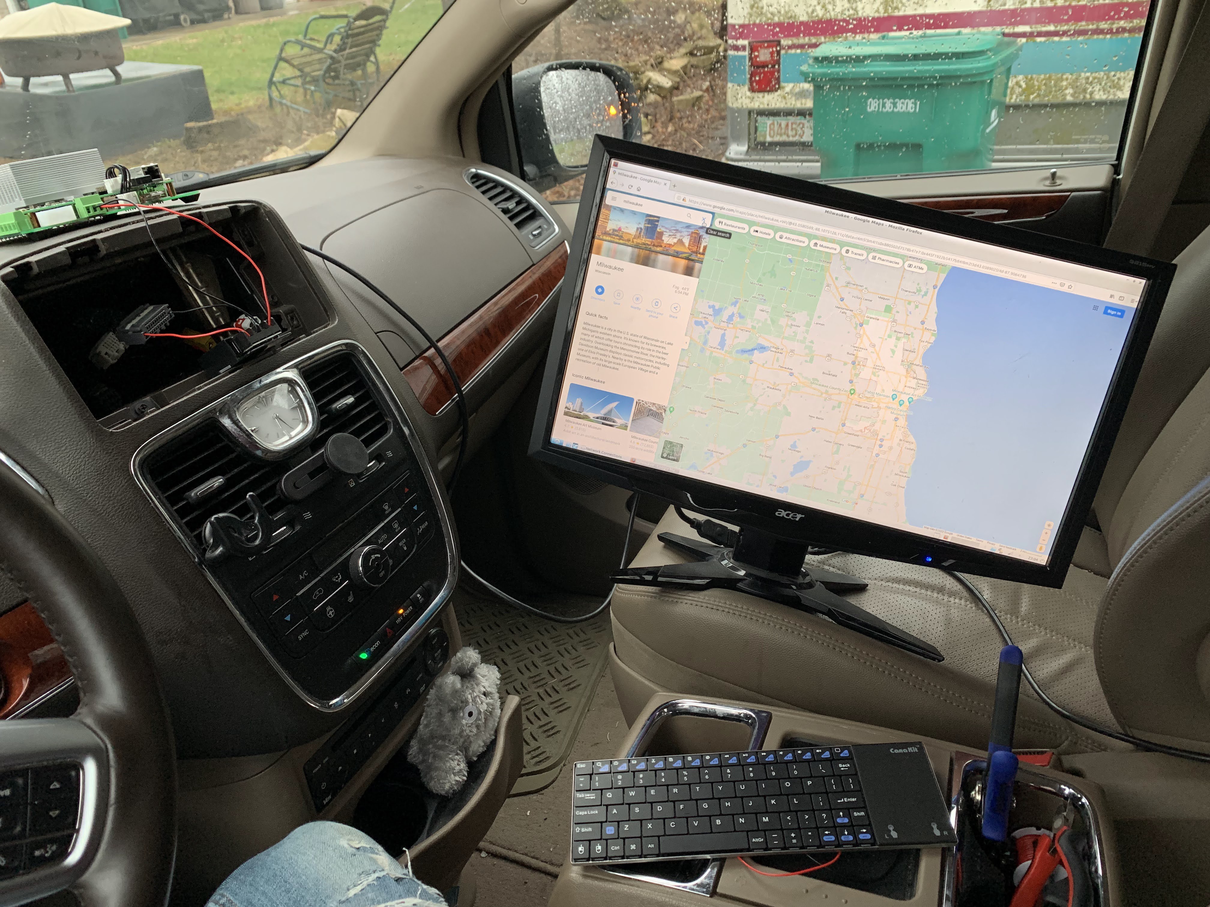
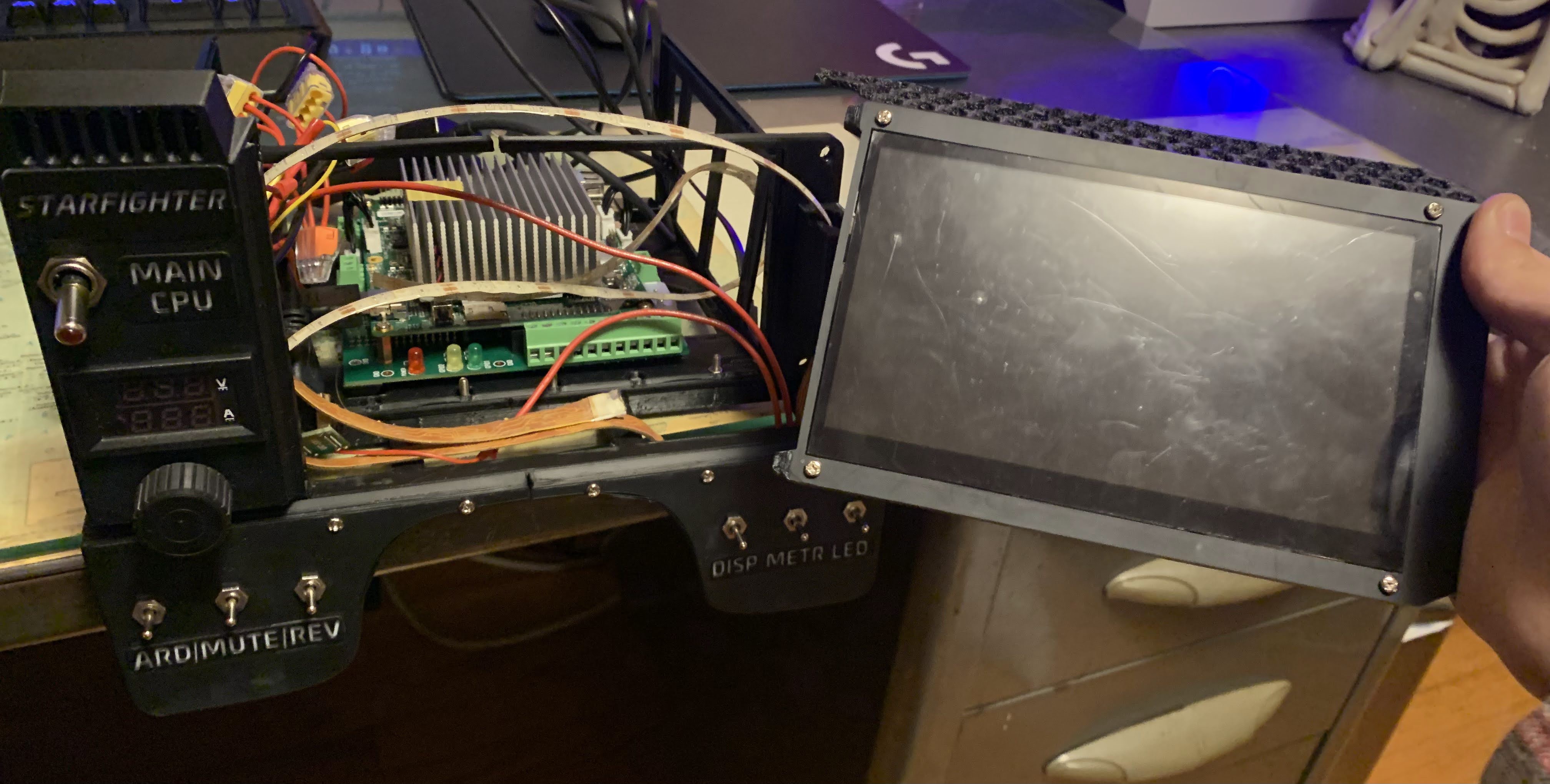
Early test of powering the Atomic Pi with my car
Although now I wouldn't exactly call this a "budget build", that was certainly the intention when I first started out. When selecting components, I typically did a bunch of research on what was out there in any particular category and then picked the most available one. "Most available" here means a combination of low price and my actual ability to get one, whether it be online or in a real store. I also wanted to reuse as much stuff that I already had on hand as I could, like from pretty early on I knew I wanted to secure some of the front facing panels with these magnetic nametag things that I had from an old job. It's free, it's super easy to implement in cad, and it makes taking the front part off to get to the guts easy and straightforward for the inevitable maintenance/ bug fixing/ showing off.
When it came to computing power, I knew I wanted something like a raspberry pi (cheap but not wimpy single board computer that's easy to learn on). Of course, so does everybody else and their mother, and I couldn't get my hands on one at the time. I had a couple of the earlier pi versions already, but if I used those then the SD cards that hold my Octoprint installs would get cold. Thus, enter the Atomic Pi. If you haven't heard of it that's okay, it seems like most people haven't. I was actually a little disappointed when I saw somebody else put an Atomic Pi in their deck contest submission; I thought I was going to be the only one. Thanks, 4KbShort. I don't know where I heard about it, but at first glance it seemed like a suitable Pi alternative. It was relatively cheap, and the few youtube videos I was able to dig up about it made it seem decently powerful. The only part missing was "easy to learn"! Oh, wait...
Legend has it that the Atomic Pi is industrial surplus: some big tech company wanted to put an Amazon Alexa on wheels so it could follow you around your house, and then for some reason nobody wanted to buy it. The project got scrapped, but they had already manufactured thousands of brains for the thing. and they had fairly decent I/O options with readily available GPIO pins, multiple serial ports, ethernet, wifi, bluetooth, and some other neat tricks like a built in amplifier that runs on 12V and a Bosch 9 axis inertial navigation sensor. As icing on the cake, it packs an Intel Atom processor which means it's x86! Rather than let these boards go to waste, the mysterious yet benevolent "Team IoT" stepped in and started selling them as single board computers at a significant discount. Tall tales aside, in the year 2022 you can get one for $50 or less on Amazon in the U.S.
The Atomic Pi definitely has its quirks, such as only accepting power input through the GPIO pins, but by far its biggest flaw is lack of support. You can find some person on the internet telling you how to do almost any hardware or software tomfoolery imaginable with a regular raspberry pi, and that's part of what makes it so great. Its intricacies are extremely well documented and it has a huge global community of helpful people surrounding it. Whatever you're trying to do with your raspberry pi, there is somebody out there who has done it before or at least knows how to. The Atomic Pi, on the other hand, has none of that. Team IoT provides some documentation, and there's a subreddit that's pretty helpful, but I ran into significant difficulty trying to learn how to configure software for it. As somebody who is only just now getting used to terminal commands and who had never installed any linux distro on anything before a few months ago, choosing to use such a niche hardware platform was definitely shooting myself in the foot when it came to learning what I was doing in the context of this project.
Of the several challenges I faced while designing and building this thing, the biggest one was time. I'm sure there are plenty of other deck builders here who would agree. It's probably obvious to some, but as I am still a student this is my first real electronics project and really the first time I've ever designed anything with this level of complexity. I vastly underestimated the time it would take, and I was surprised to find myself spending whole weeks at a time on just CAD. In order to get this project to a state that I was comfortable submitting to the contest before the deadline, I had to cut a lot of corners. I have a lot more features that are planned, some quite robustly, but I just didn't have time to implement them. For instance, Starfighter doesn't actually have GPS connectivity yet, because even though I already bought a gps chip I couldn't figure out how to set up a serial connection between it and the Atomic Pi and then lost all that progress anyway when I switched operating systems. Another thing is that a lot of the printed parts are lower quality than I would like, because the night before I was running all 3 of my printers nonstop and didn't have time for reprints or spending hours tuning my slicer profiles. I only had one printer set up to print ABS (and also only one roll of ABS filament), so several parts had to be printed out of PLA on my backup Ender 3 that has all sorts of mechanical issues. The resin gods were nice to me however, and I didn't have any issues with the more decorative parts that I printed on my Elegoo Saturn.
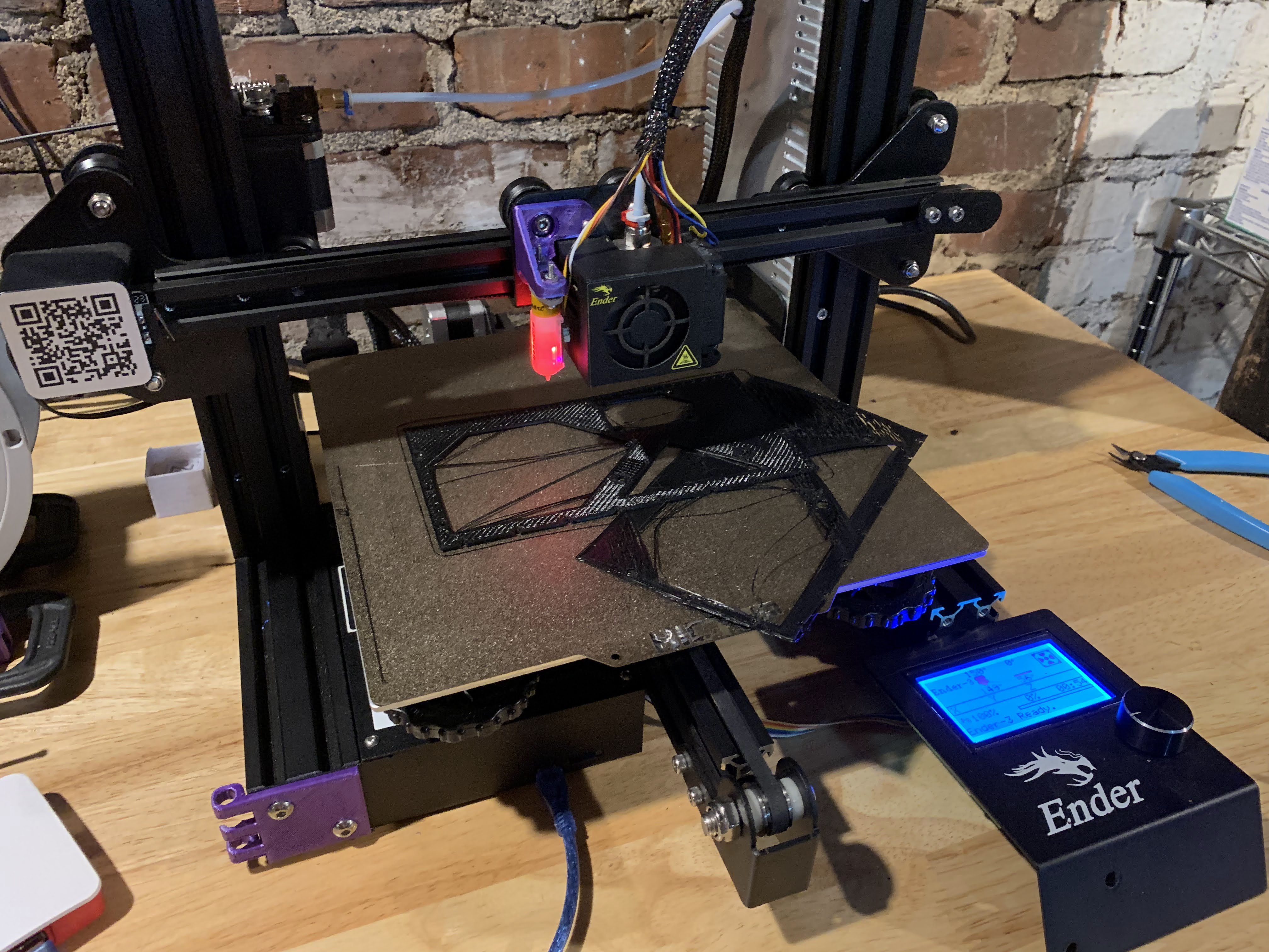
Hmm, I'm pretty sure that's not what the STL looked like...