 Sp4m
Sp4mOnce the paint was dry, I had to do a materials test, to make sure I can get the finish I'm hoping for. I don't want my chassis to feel like a cheap 3D printed hunk of plastic. By spending time and effort, I can turn a cheap hunk of plastic into an expensive one!
(at least in terms of resources spent)
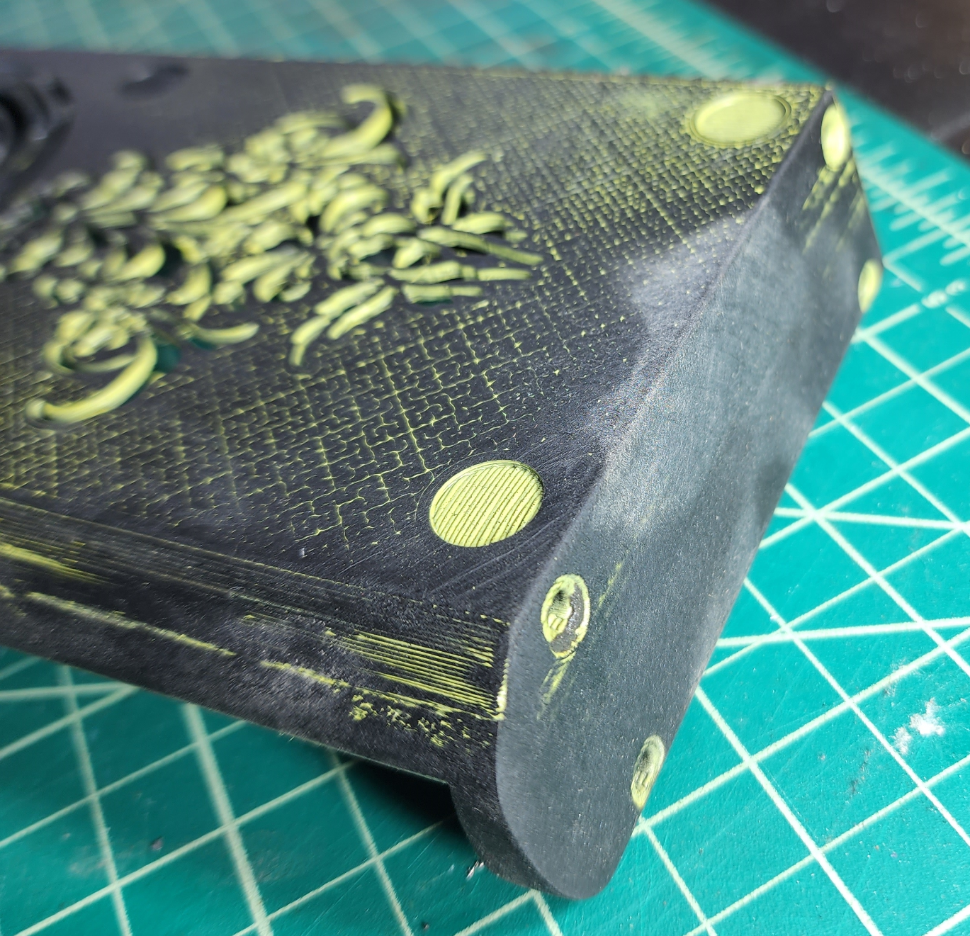
I spent about 20 minutes and a new sheet of fine grain sand paper to wet-sand this down this far.
WET sanding is important. I don't know why exactly, but dry sanding seems to make the layers smooth and fuse, whereas dry sanding seems to make the layers fray and separate. I bet it has something to do with heat, but if you know for sure, please share.
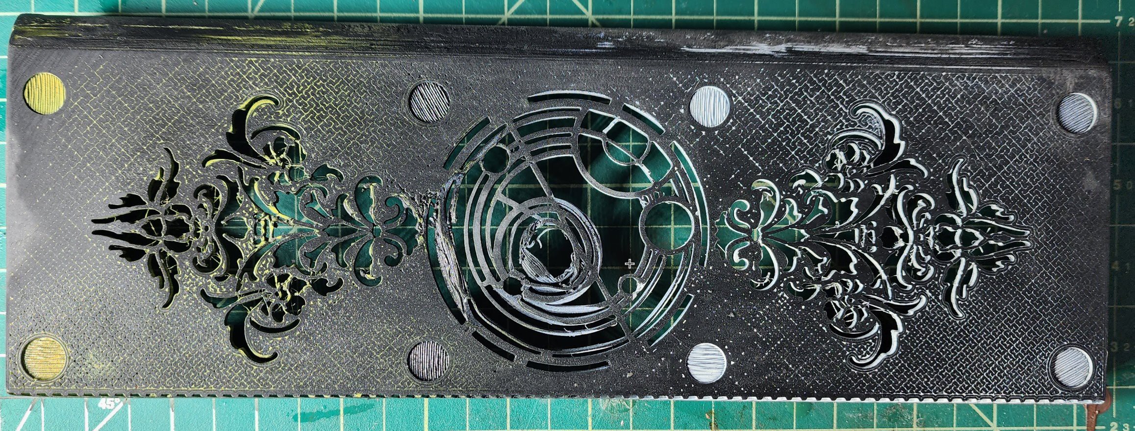
Close up of the side of the chassis. Layer lines are pretty much gone. There are still some along the front curve, but printing with support for that area will help with the uneven angle on that part of the model.
The technique of painting then sanding looks particularly good with specific infill styles, and color choices.
My preferred infill is Hilbert Curve (available from Prusa Slicer), and it looks particularly rich with a matte black paint on a metallic silver filament. Those color choices also compliment filigree patterns.
(For a good time, check out my SFF Desktop PC: https://imgur.com/0o2UD64)
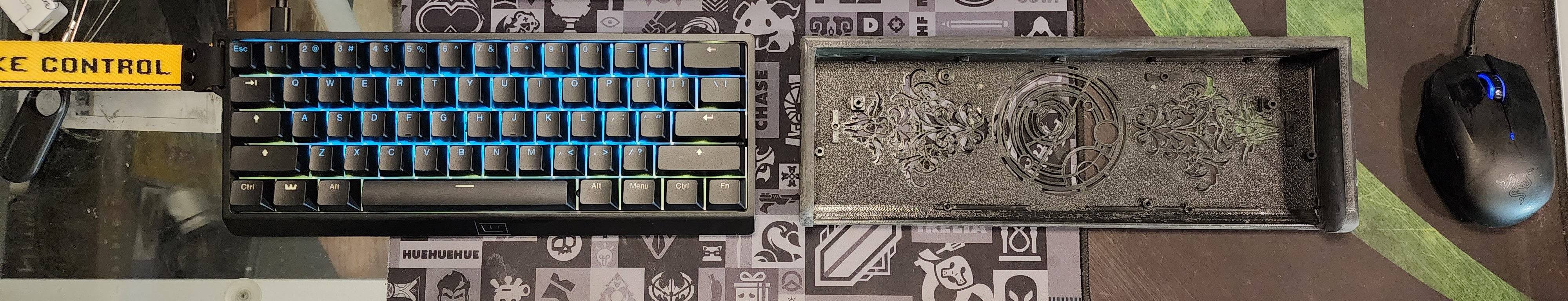
Next step is to verify that the positioning of my mounts and cutouts work, by trying out my keyboard in the new chassis!
This isn't a complicated procedure, but Wooting makes it even easier with an instructional video!
I can hardly believe it, but the module is a perfect fit!
I left a .5mm gap around the board, as reported by the CAD files I downloaded from wooting. That would give me 1mm of play across the X and Y , and it looks like that was perfect. The module mounts cleanly, with very little gaps on any side.
And the USB C port is centered perfectly. The original case has a tight fit around the USB C port, but this "generous" style is common for after-market cases, to help account for small variations in 60% keyboard modules.

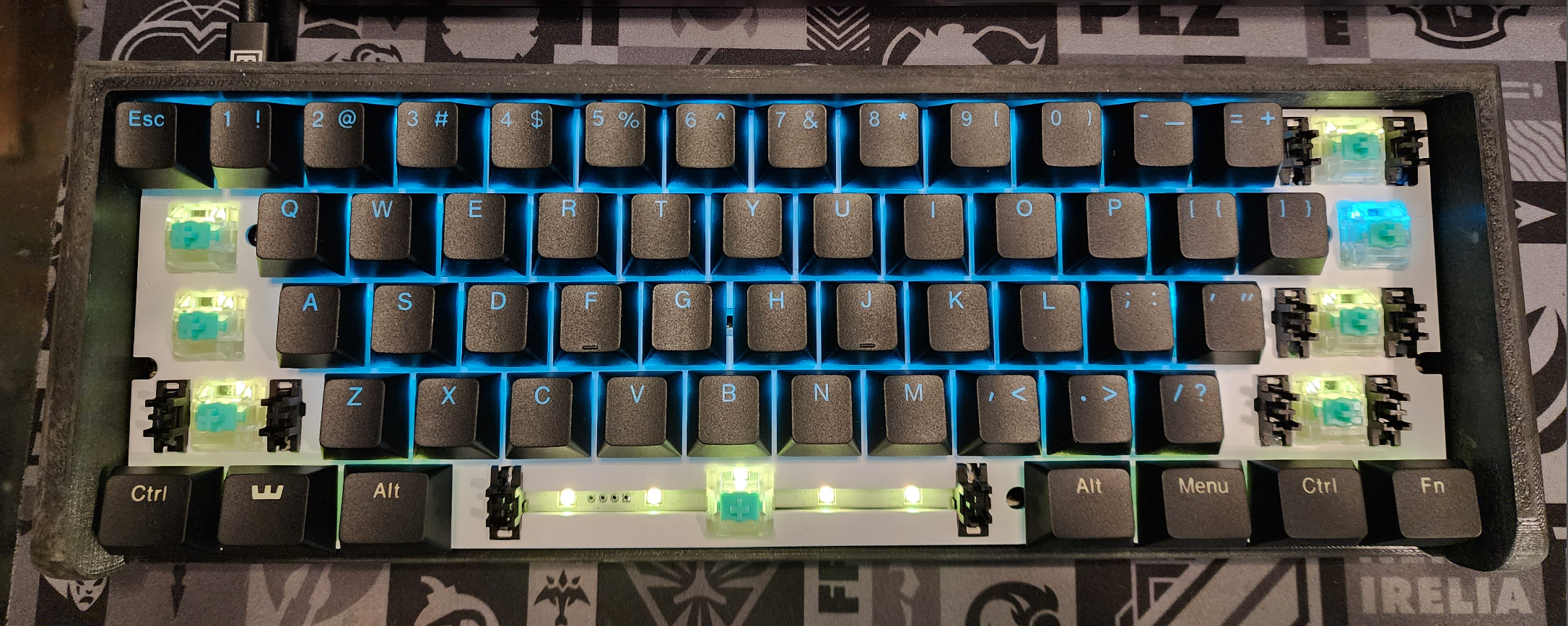
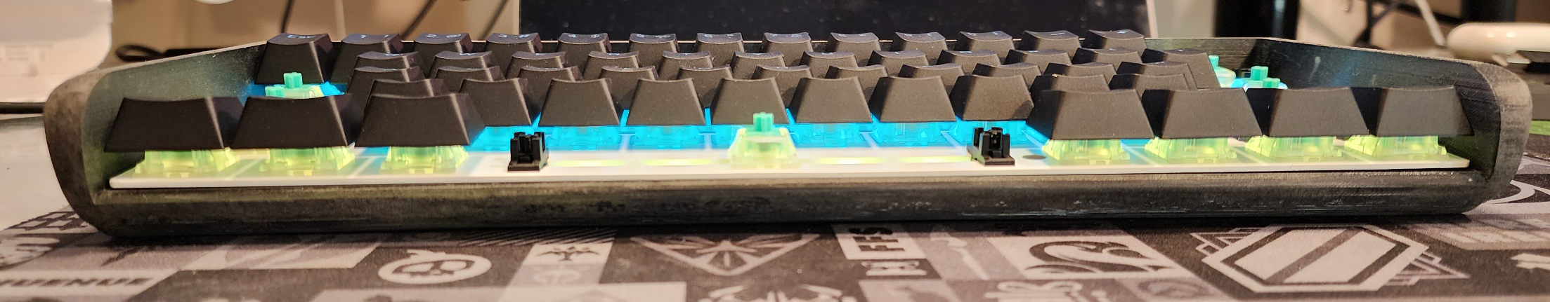
From the front, you can see that the keys extend just a little past the top of the chassis in the back. This is expected, because the module is mounted at approximately a 6 degree angle. Keycaps and switches are not part of the CAD model provided, so I wasn't sure how this last step would look.
I have to say that I am pleased. The wooting keyboard includes two rows of dense foam at the bottom, and when included, my chassis retains the tight "thock" of the original.
The bottom of the chassis is OKAY. The foam was never meant to be a showpiece, and the wrinkles are a little distracting. You know, for a part of the keyboard that no one will EVER SEE. But I have a cunning plan.

I've made some minor adjustments to the model.. Mostly I traced over the central emblem to ensure geometric consistency, built in a little more support, and thicken up some troublingly thin lines. The next version should be ready for production!
Discussions
Become a Hackaday.io Member
Create an account to leave a comment. Already have an account? Log In.