 Maksim Surguy
Now that I have a proof of concept 3D printed model of the display, it is time to design a circuit board for 7 WS2812B LEDs that will light up the numbers on the display.
This time I decided to use KiCad as an opportunity to learn proper circuit board building and after the schematics design is finished, I will finally put my new laser printer that I got on Cyber Monday to a good use to create a Printed Circuit Board (hint: toner transfer method)!
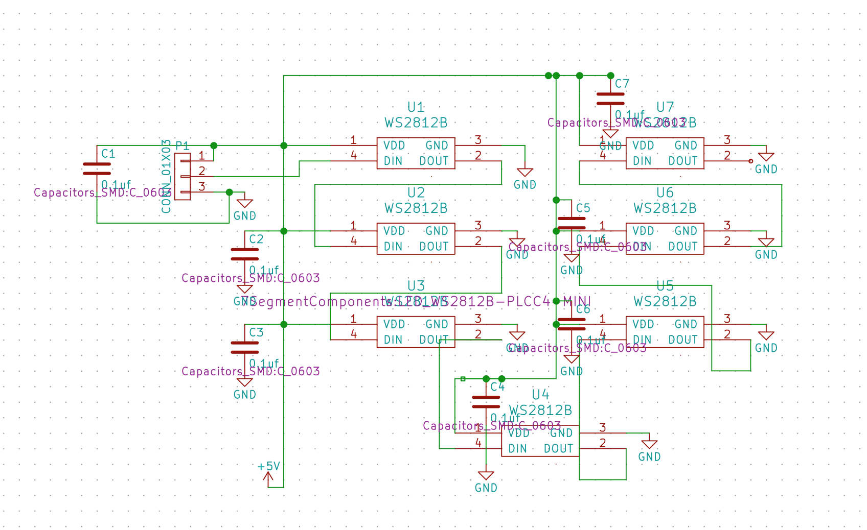
The schematics design for this display is very simple and consist of only two kinds of components: WS2812B LEDs and capacitors. Each LED of this type has input and output pin so the series of LEDs need to be put together in a particular way: data output of one LED needs to feed into data input of another LED.
Here's the design of the schematics in KiCad's EESchema before it was exported to PCBNew:
In PCBNew, I placed the components at distances that correspond to my 3D printed model, then ran Freerouter to create a layout with minimum traces and no through hole connections. I then had to manually adjust a few pads and placements in order to use space efficiently. After about 3 tries of printing the circuit board and etching it (picture below), I was able to make one that worked.

I've attached the circuit board schematics and the PCB design in Files section of this project.
Discussions
Become a Hackaday.io Member
Create an account to leave a comment. Already have an account? Log In.