 Mx. Jack Nelson
Identifying the sensors
TJ knows the position of his gears through the use of five rudimentary rotary encoders. Utilizing a basic form of Gray Code, these encoders report their position as being in one of four possible states using two wires.
Each encoder consists of three metal contacts that rotate over concentric circular tracks on a PCB. The tracks for Contact A and Contact B have metal traces covering only half of their circular path, the other half is bare. You can see the upper and lower half of two encoders in the photos below:

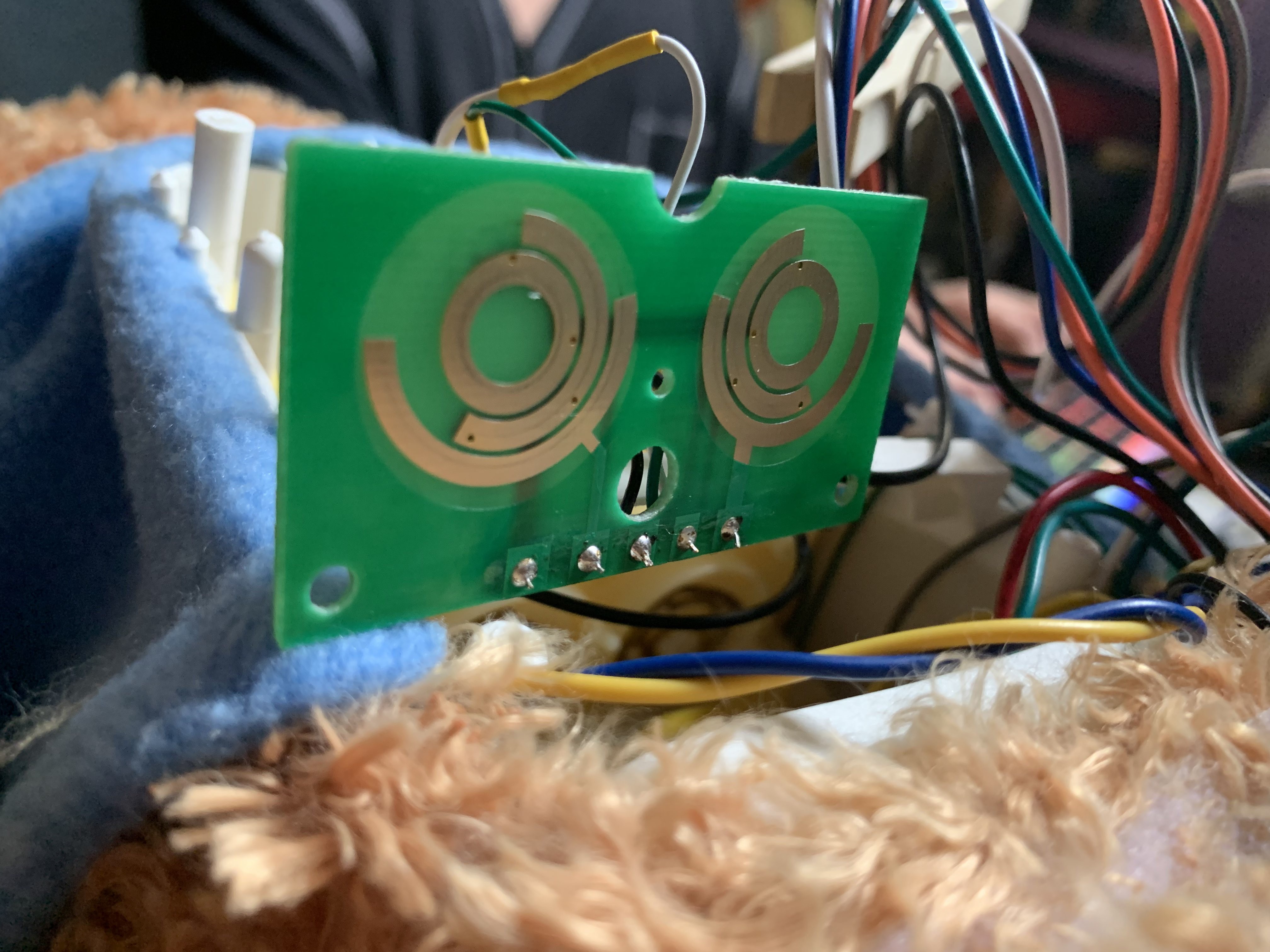
As the encoder rotates, these contacts are connected to ground for half of their rotation, and disconnected from ground during the other half. The innermost track is solid, and connected to ground. As the encoder rotates, the third Contact C stays connected to this ground track at all times.
The outer half circle trace for Contact B is advanced approximately 90 degrees compared to the inner trace for Contact A. This means that Contact A and Contact B will connect and disconnect from ground at differing times throughout one complete rotation. By changing the rotational relationship between the inner and outer trace, it is possible to more precisely identify certain positions within the full rotation, at the expense of resolution in the other positions.
By combining the readings of contact A and contact B, it is possible to know the position of the encoder. The possible states are:
- On/On
- On/Off
- Off/On
- Off/Off
Rotary encoder example:
To illustrate a concrete example, let’s look at the single rotary encoder in TJ’s head. We’ll call it Encoder 1. Encoder 1 is attached to the gears that run TJ’s eye blink and ear wiggle loop. It’s buried inside the head gearbox, and since I don’t want to mess up those gears I’ve never opened the head gearbox and thusly I’ve never actually seen Sensor 1, just interacted with its wires. We’ll call those wires A and B. In real life these are the orange and grey wires that come out of TJ’s head and and plug into the side connector of his main board.
We set our GPIO with internal pull-ups and attach wires A and B. When we apply forward power to Motor 1, TJ’s eyes will shut, then open, then his ears will wiggle, and then his eyes will shut again as the loop repeats. At the moment in the loop when TJ’s eyes are fully open, Contact A and Contact B are both disconnected from ground, and both GPIO will read as logical True. Because the half-circle tracks inside the encoder are offset from each other, the state in which both A and B read True exists for only a certain percentage of degrees out of the full rotation of the loop. You can see this rotational loop represented in our comments to ourself in our code.
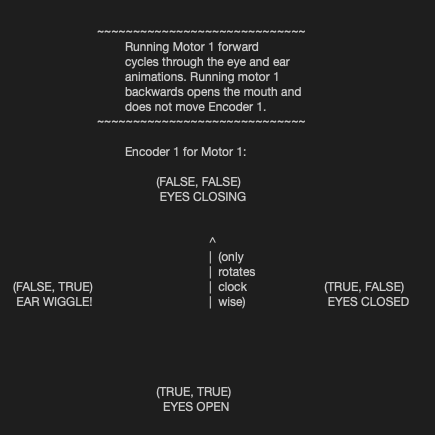 As the loop continues into ear wiggling, Encoder 1’s A wire will connect to ground again while B stays disconnected, and our GPIO reads False/True. As the ears finish wiggling and the eyes begin to close again, wire B will also connect to ground, resulting in a False/False state. At the moment when TJ’s eyes are fully shut, A wire disconnects, and the GPIO reads True/False. It will continue reading True/False until our loop gets to the top again, at which point Encoder 1 will report True/True, telling us that TJ’s eyes are in the full open position.
Remaining encoders:
Encoders 2 and 3 track TJ’s left arm position and head nod position, as controlled by Motor 2. Encoders 4 and 5 track TJ’s right arm position and head turn position, as controlled by Motor 3. All four of them are wired and read in the same fashion as Encoder 1 in the head. Notably, TJ’s mouth has no positional encoding, and its operation depends entirely on timing.
Motor and encoder summary:
So, as you can see, helping TJ move to any new position is as easy as spinning the correct motor in the proper direction and waiting until the associated encoder reads the correct value, at which point you stop the motor. Our code below shows an example of this for his eyes being open (we check the encoder twice as a debounce).
print('opening eyes...')
theValues = (Quadrants(orangeWire, greyWire), Quadrants(orangeWire, greyWire)) #check twice
while theValues != ( (True, True),(True, True) ): #while eyes are not open
    #print(bool(Quadrants()[0]), bool(Quadrants()[1]))
    if kit.motor1.throttle != .75:
        kit.motor1.throttle = .75     theValues = (Quadrants(orangeWire, greyWire), Quadrants(orangeWire, greyWire)) #check twice
    #await asyncio.sleep(0)
time.sleep(.1)
kit.motor1.throttle = 0
print('eyes open.')
#kit.motor1.throttle = None time.sleep(.1)
Discussions
Become a Hackaday.io Member
Create an account to leave a comment. Already have an account? Log In.