 Dave Collins
Introduction:
So over the last week or so, I have been building on trying to test out HBSound at speed in a way that verifies all of the different subsystems of the module. In order to do that I had to make some slight modifications to the system rom on the HB6809. This was quite the learning curve and along the way I managed to pick up "Learn Multiplatform Assembly Vol 2" which covers the 6809 (as well as RISC V, the PDP-11 and a handful of other CPUs.). I Highly recommend this book!
Along the way I settled on writing the test program in C, because my assembly fluency is still an ongoing process. This was a relative success, and I managed to get a functional test program that streams the audio frame data to the card over the bus, and also simultaneously updates the terminal with output. Its actually quite a good demonstration of the capabilities of the interface, that even with a higher level un-optimized language can produce working output without the use of any direct assembly language programing.
Proof PCBs for Final Testing:
So almost as soon as I finished building the prototypes, and determining the fixes our sponsor PCBWay stepped up and offered to re-make and ship new proofs to test the design changes. I also ordered a small PCB to start working on the ROM / RAM expansion which I was able to build test and verify, everything was working very well (more on that later).
The PCB's came in about a week, to my door everything was perfect! I did have some issues with DHL, but this can hardly be blamed on PCBWay. I submitted both orders, they set up production and delivered both in the same box, despite both projects having completely different build times. I was very impressed that I didn't have to wait for a second box.
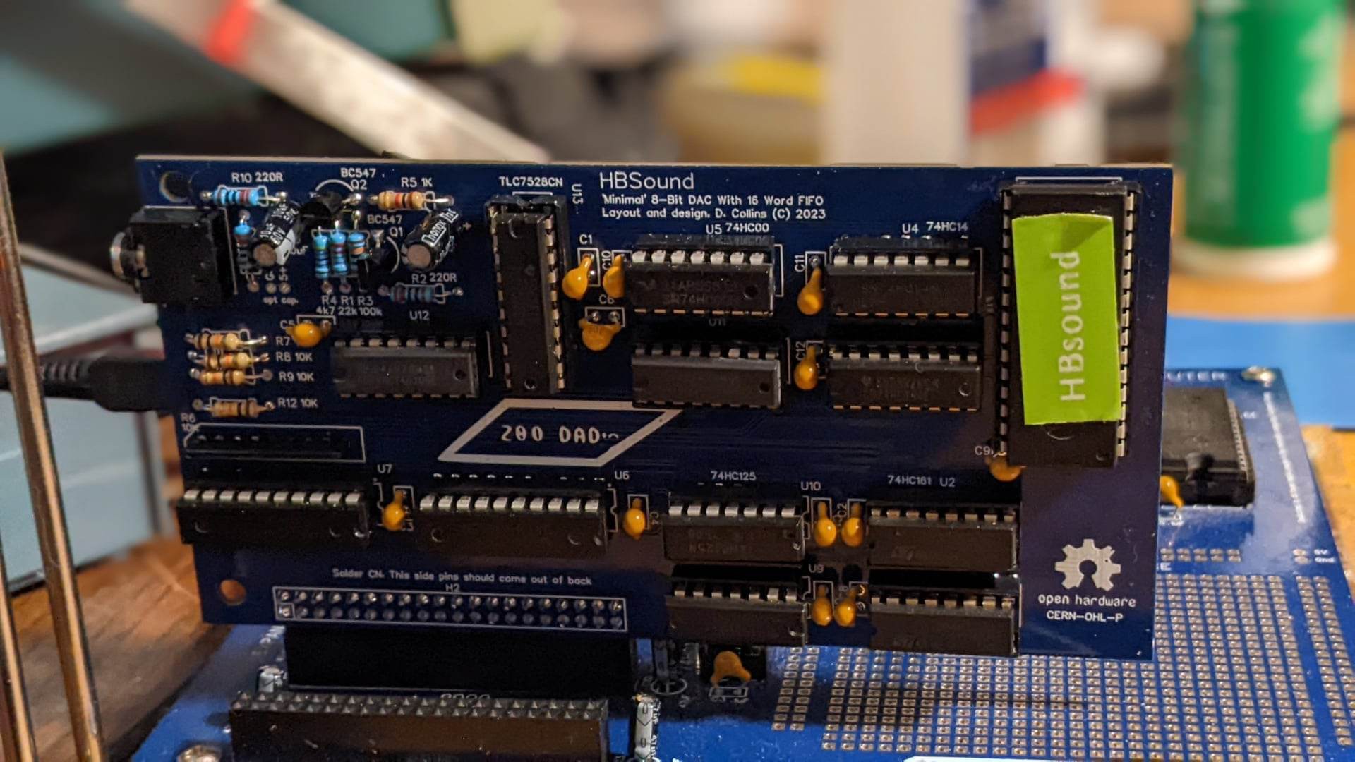
The HBSound Proofs were ordered in this lovely blue solder mask, I wanted them to match the main system PCB's final build color so It was good to see that when you request a mask color change (for most, but not all) there wasn't an extra charge. Additionally I had done quite a bit of work adding "Stitching" vias to the revised design. This is a technique I picked up from watching the Byte Attic ( aka Bernardo Kastrup). This is a way of joining copper fields with a trace and two vias to transfer connection between two isolated areas of the board. This allowed for no larger areas of the copper fill to be missed by the EDA software, and provides for a cleaner return path to ground for all devices. Even though this is not a high speed design, we are mixing analog and digital ground planes without a multi-layer board, and so I wanted the coverage to be as consistent as possible.
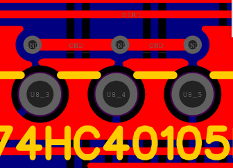
The Added stitching vias to the design did not change the price, and even with the close drill distance and detailed work involved in getting these tiny additions the actual PCBs were spot on and perfect, there were no shorts or issues even with the close clearance in some areas. Especially next to the bus connector:

Or this section here next to one of the FIFO chips:
Over all I was quite pleased with the boards that I had made and I am continued to be blown away by the access to these kinds of prototyping services.
A Pathetic way to play songs PathiTrack6809:
I wrote a test program in C It is a simple tracker program that builds 15 byte sample frames from a per-calculated list of timing count data, sends them to the card when the buffer is empty (until it shows full). Essentially the loop is simple:
- Check to see if buffer is empty if so
- send frame data until its full unless it is not then
- do other stuff while waiting,
- periodically checking if the buffer is empty
- update tracker display
- repeat
A document describing the interface for developers can be found in the GitHub for this project it is located at: https://github.com/lindoran/HBSound/tree/main/Documentation
Additionally there is some code for calling the character output routines, which are built into the machine language monitor ASSIST09. This was explained in a post over at the HB6809 Hackaday.io project page.
Since the computer only currently has 32kb of RAM storing unsigned raw 8 bit samples gets very spendy as far as how many ms of playback you can actually fit (just a few seconds). RLE would help a bit, but it would depend on how many bytes actually repeat in the sequence. You could go further by interrelation and soft augmenting the bit depth by limiting the actual levels to 6 or 5 bit resolution but this would reduce quality but would almost definitely produce more sequential data. The actual decoding algorithm would have to be written in assembly language to be fast enough in order to not under run the buffer. I suspect this kind of coding was used in systems that produced digital audio using non-conventional means like in the Super Nintendo Tales of Phantaisia, or Ghost Busters for the C64.
The first unique subroutine is simply to fill the buffer. We use pointers to define the location in memory of the device, and these are set by a '#DEFINE' statement at the top of the source. Essentially, what this does is to peek at the flags on the HBSound until it sees the value 2. This indicates the buffer is full, if it sees a zero set in the frequency count variable it skips over the square wave generation loop, which skips the note completely (sends no transition data.) The If statement, checks to see if the count is reached and if it has been then it inverts the frequencyState variable which sets up a 50 % duty cycle at the output of the dac until a counter defining the delay expires, then a new note is sent.
void fillBuffer (unsigned char maxFrequencyCount) {
    while (*flags != 2) {       // while not full
        if (maxFrequencyCount == 0)  {           // handles control code
            frequencyState = 0;
            goto CNTCODE;
        }

        frequencyCount++;

        if (frequencyCount == maxFrequencyCount) {
            frequencyState = !frequencyState;   //switch dac between high and low
            frequencyCount = 0;
        }
        CNTCODE:
        *sample = frequencyState;
    }
}
The main subroutine manages sending the data to the screen and calls the fillBuffer subroutine, It builds the screen using printf statements, and then in between frames updates the screen using a combination of printf statements and ANSI / VT100 Control codes, since the terminal has its own screen buffer and control code processing we can sort of "cheat" some of the functionality of the results.
int main() {
    // console redirect for CMOC
    setConsoleOutHook(newOutputRoutine);

    // clear the screen and set up the on screen graphics
    printf("%c[2J",27);
    printf("---------------+\n");
    printf("               |\n");
    printf("               |\n");
    printf("               |\n");
    printf("               |\n");
    printf("               |\n");
    printf("               |\n");
    printf("               |\n");
    printf("               |\n");
    printf("               |\n");
    printf("---------------+\n");
    printf("Frame Note Tone\n\n");
    printf("PathiTrack6809 (C) - 2023 D.Collins\n\n");
    printf("Mario Bros ""Ground Theme"" \n");
    printf("Original Arr. Koji Kondo,1985");

    printf("%c[H",27);

    *control = 3;  //Set DAC Clock to slowest speed
    unsigned int tones = sizeof(noteslist);
    unsigned int note;
    for (note = 0; note < tones ; note++) {  // determines what note we are on
        scpos++;
        if (scpos == 9) {                    //this manages the tracker window
            printf("%c[H",27);
            scpos = 0;
        }
        // right before the note plays...
        printf("\n    : %3d | %2d",note,noteslist[note]);  // prints curent note
        // this is one note
        while (bufferPeriod != BPM) {
            while (*flags !=1) {        //while not empty
              // do stuff here
            }
            bufferPeriod++;
            fillBuffer(noteslist[note]);
            // or do stuff here!
            printf("%c%d",13,bufferPeriod);        // prints the position in frame
        }
    frequencyCount = 0;    // counter for frequency
    frequencyState = 0;    // state of frequency
    bufferPeriod = 0;
    }
    scpos = 0;
    *control = 0;
    printf("%c[18;0H",27);
    softStart();            //Return to monitor
    return(0);
}
The amount of time between frames is approximately 2mS -- this is an eternity for a CPU running at almost 2 MHz. Since much of those cycles are taken up by the relatively robust printf statement (it ads a large chunk of assembly code to the end result) we have to be kind of thrifty with what we do. I probably could have used control codes to do a scrolling note pan, like most trackers have but instead I settled for overwriting from the top down, and using the carriage return to move the cursor back to the beginning of the first field of the tracker data. I did use tabulated formatting in the printf statement which is the lions share of the code from the standard lib. If this program were written in assembly it would most definitely be considerably smaller and we might even be able to pull of a little visualizer in ASCII, or forgo those completely and do a much faster data rate
Gerber availability:
As of today the Gerber files are uploaded to the repository at:
https://github.com/lindoran/HBSound
I consider this project in more or less a finished state, its been a long arduous journey but I think I learned a ton during this project and I am excited to translate that to the next one.
Final design reflections:
Over all I am very happy with the results here, but no design is perfect, and I do have some reflections on what could be done better or changed here to make things work a bit nicer. Over all the EEPROM worked good as a clock divider, it is however kind of a waist of space on the board and I believe the whole design could have been under the cheaper 100x100 size spec if I had opted for some kind of custom logic or a programmable controller. The use of a ATTTiny chip here (as there are only 2 control lines) would have been the most likely choice, the only issue being in that case the clock synchronization would have to be completely done over again. Even a GAL has a smaller footprint and well within the limits of generation of a single low facing pulse based on 4 addresses; I may have even been able to work in the clock synchronization as well.
The TLC7528CN has a active low !WR line, and while the datasheet calls out this is to latch the data into the DAC; I had found through testing that what the datasheet calls a latch is more or less this is a sample and hold. This meant that I could leave the inputs wide open by placing the !WR low all the time. This makes the discrete part behave more like a resistor dac. The only issue with this is it generates a few spurious noise like artifacts as the outputs of the flexible latch settle. In the original DSS design which uses a simple ladder dac you see these same artifacts, as there is no way to stop the analog design from seeing every transition. These could be eliminated completely by using the DOR line from the flexible latches (or simply inverting the output of the or gate). Since this simplified the design and it had worked more or less in testing I didn't really feel the need to disable the DAC inputs especially since the frequency they change at is incredibly slow (a few kHz). Lastly the DAC itself is a two channel dac, it would technically be possible to duplicate everything on the board and create a two channel output, adding two of everything would mean more chips / logic and a significantly more expensive card.
What's next:
So next I'd like to switch gears and look at the over all design. I'd like to work on a memory / ram rom expansion and I've thought about doing a 128k ram / 40k rom expansion. Additionally threes some work that could be done eliminating the recursion in the combo rom. Essentially there are 2 sets of serial control subroutines, when really all we need is 1 set. Since the design I am looking at would use system calls from ASSIST09 to control the screen and input, I would need to go over extended basic and eliminate the recursion. I would like to change the decoding circuitry and perhaps design a custom GAL that does all of the address selection. Have a number of projects centered around restoring a ZX81. But for now the plan is to take a few days off, as I have been working fairly consistently since about a week ago to get everything finished for a weekend release :)
If anybody has any questions please feel free to leave a note, and thanks for taking the time to read about my mad projects!
Discussions
Become a Hackaday.io Member
Create an account to leave a comment. Already have an account? Log In.