 Thomas Flayols
I've played with the android app that connect to the battery via bluetooth. At first it looks really interesting with capacity %, charge and discharge current measurement, temperature etc.
I've also took one apart to check the circuit:
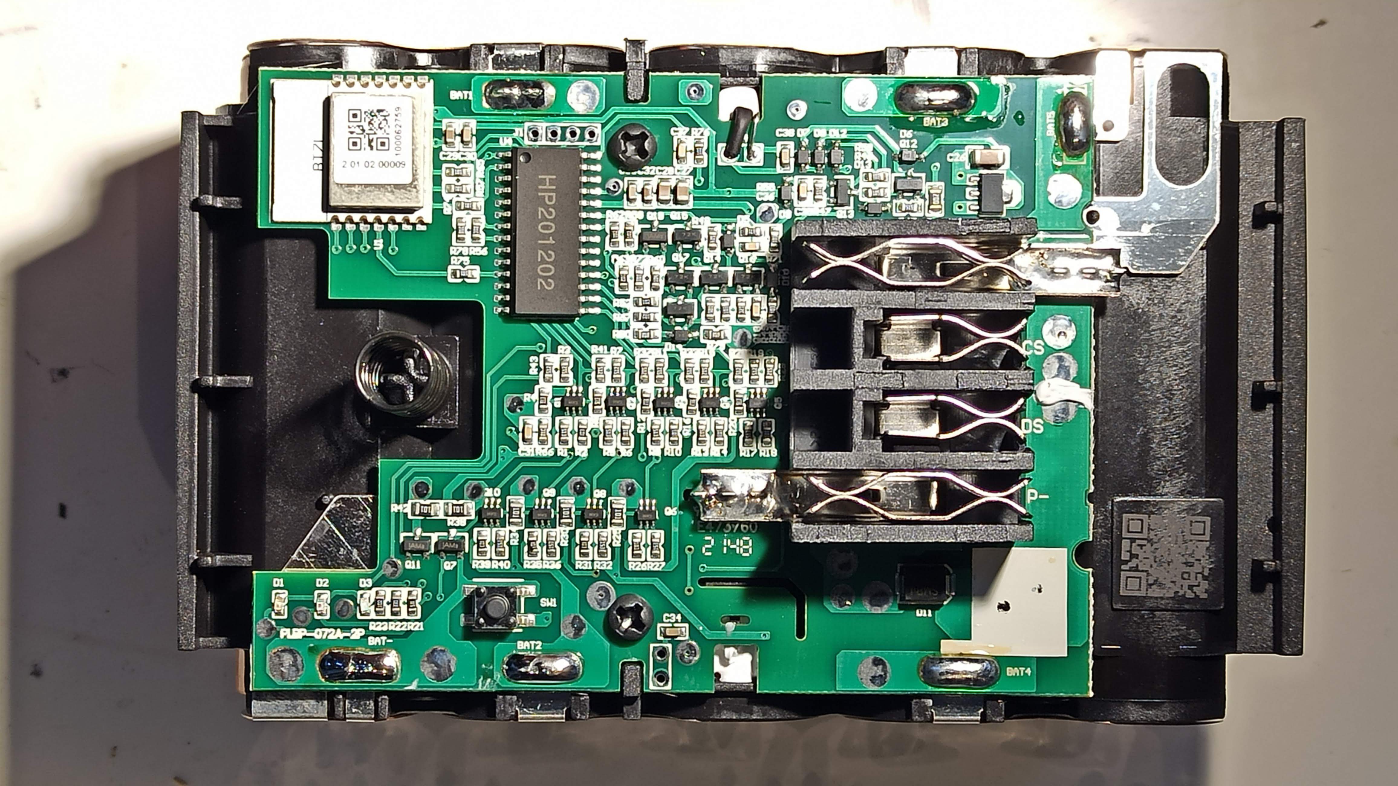
We can see a few interesting things:
The bluetooth module is labeled BT7L and we can inf more information here https://developer.tuya.com/en/docs/iot/bt7l?id=K96gqp1dp6iiw It's a system on chip with programable MCU. The lidl app ask me for an OTA update of the battery. Good thing to keep in mind if we really want to push the hack and design a custom firmware ! There is also a pin header near the chipset that I suspect to be a programming or debug interface.
We can see a the balancing circuitry in the middle.
On the left corner there is a push button that allows to wake up the bluetooth, and to show the charge state on 3 LEDs. A long press can enable / disable the BT.
As I expected from other reviews (https://www.reddit.com/r/AskElectronics/comments/s2wswc/how_are_the_new_lidl_parkside_batteries_limit_the/)
the output power pins are directly connected to the cells terminals (via a fuse).
Current measurement?!
I was thinking that the fuse (top right corner) was acting as a shunt resistor as well, to provide the "charge/discharge current" in the app.
If I were to design this, I'd have put the shunt resistor on the lowside as it simplify a lot the design ! And surely they did not bother with a High side current measurement, this is just a Fuse.
How does the app report the current status then?! Here come the disappointment.
I've hooked up the battery to a resistive load to draw 4Amps from the battery, run the app, and it shows ... 0A !
I think the battery get this information from the tool itself. so there is some sort of communication going on.
Pinouts of the battery
From the PCB silkscreen:
- P+ (Positive cell terminals)
- CS ?
- DS ?
- P- (Negative cell terminals)
I measured 12k Ohm between P- and CS, and 512 kOhm between P- and DS.
CS pin is present on the charger and labeled "ID" (not a "smart" charger). DS in not.
I do not have tools to spy the communication, If anyone have information please comment.
My guess is that the battery need to be compatible with the old line. The fast charger needs to know which type of battery are installed. It also need to read the temperature of the cell to safely charge them.
The tool needs to know the battery voltage to protect from over discharge, but of course it can do this by simply measure it internally.
I've connected a scope to the DS and CS lines while discharging the battery via resistive load and observed nothing (0V).
It is difficult to follow the traces without accessing the bottom of the PCB.
What next?
I really would like to RE the wired communication, but I don't want to buy expensive tool. I will have a look at the communication with the charger.
Discussions
Become a Hackaday.io Member
Create an account to leave a comment. Already have an account? Log In.
Hey I was also interested in this bat. https://github.com/PlusPlus-ua/ha_tuya_ble/issues/100
Are you sure? yes | no