 Xtreme Tech
Hey there, folks! So, I totally get it, I promised this post for Friday, but hey, cut me some slack, it's only been a couple of days! Time flies when you're, um, "planning," right?
But enough with the excuses, here's the post I've been talking about!
I had switch to an ATmega328P IC in order to make the radio more compact and power efficient. However, programming this IC did present its own set of challenges.
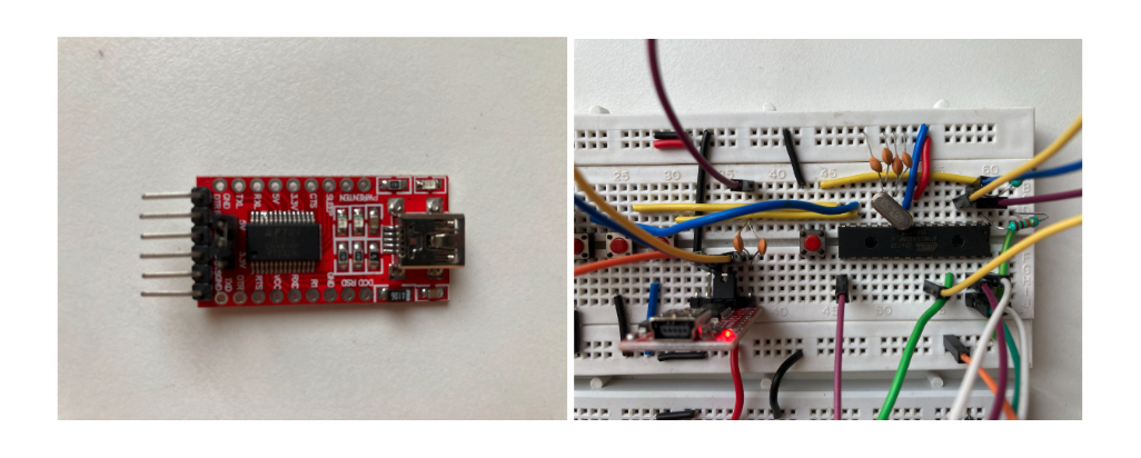
In order to program this board using your laptop you will have to make the following connections :
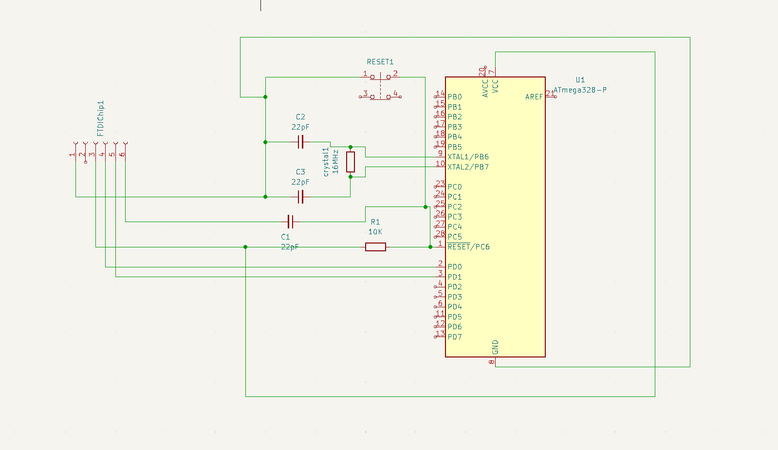
Once connected the circuit would look somewhat like this :
Now it's time to upload your code. So open your Arduino IDE and make the following changes :
1. Tools > Board > Select "Arduino Uno"
2. Tools > Processor > Select "ATmega328P (Old Bootloader)"
3. Tools > Programmer > Select " Arduino as ISP (ATmega32U4)"
4. Tools > Port > Select the Appropriate Port
Next connect the above circuit to your laptop through a USB 2.0 A to USB 2.0 Mini B (same cable you would use to connect an Arduino nano to your computer). Now, here comes the most important part : uploading the code.
Once you click the upload button wait for the compiling to finish. As soon as it says "Done compiling" and the "Uploading..." message arrives, immediately press the reset button for 1 - 2 seconds. Within a few seconds a "Done uploading" message should arrive which indicates that your code has been successfully uploaded to the IC.
Despite all this if the code errors out with the message "avrdude: stk500_recv(): ... " , then disconnect the USB cable and try again. It may take a few frustrating attempts but your code will get uploaded eventually.
Bonus :
Now that you got your code running on the ATmega328P you may be wondering (at least I did) "Do I have to go through this wild connection process every single time I want to upload an update?".
Guess what? Not anymore!
I've designed a PCB to handle all that for you instead!
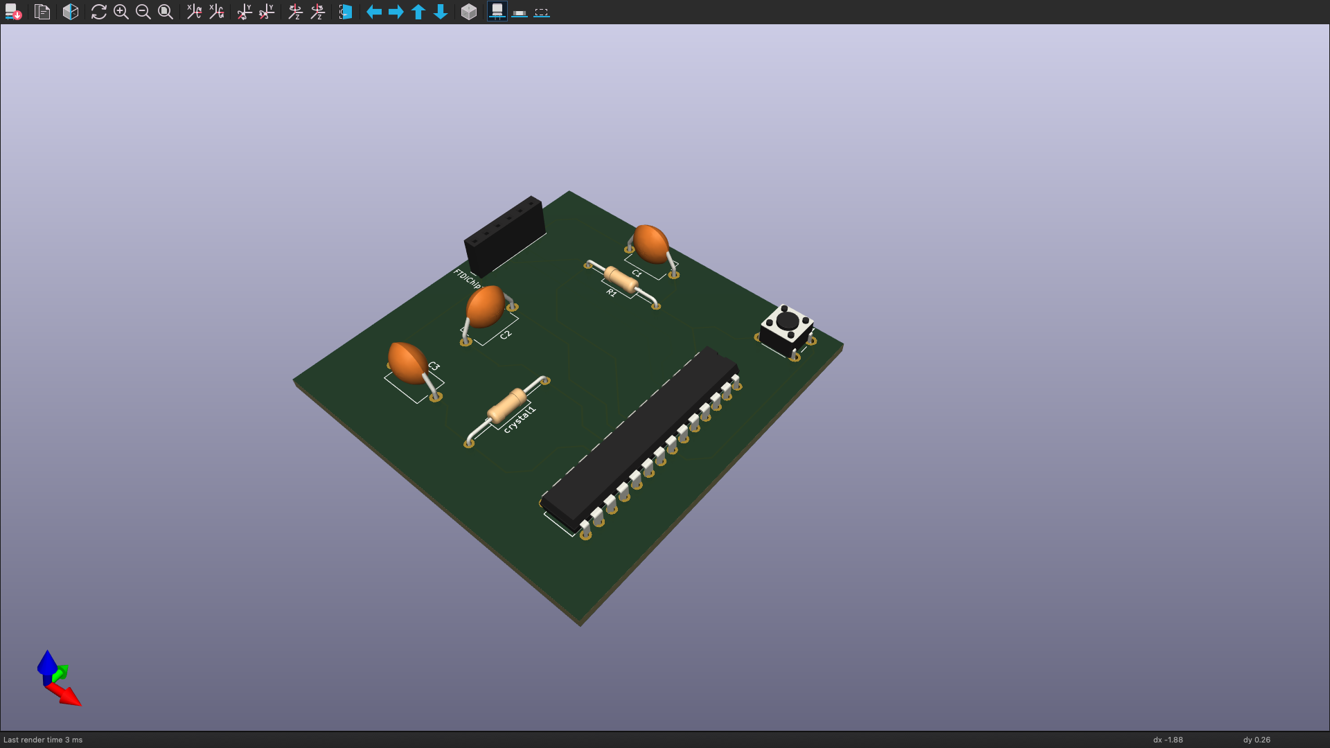
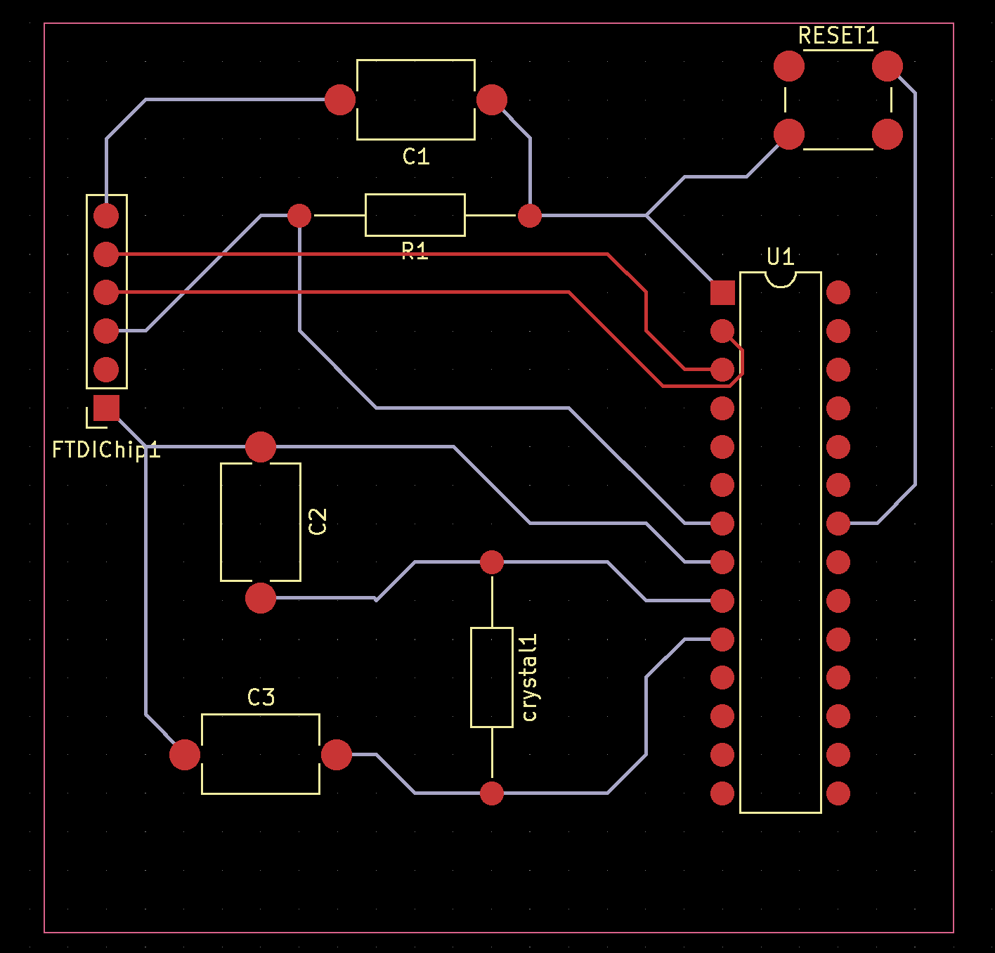
I whipped up this PCB using KiCad. If any of you are itching to get your hands on it for printing, just drop a comment down below, and I'll hook you up with the zip file !
And that's a wrap for this week, my friends!
As for the next post, well, it might take a little longer because I'm knee-deep in designing the PCB for the radio. But don't worry, I'll be back with more electrifying content soon! Until then have a great day and keep innovating !
Discussions
Become a Hackaday.io Member
Create an account to leave a comment. Already have an account? Log In.