A GPS tracker is a navigation device generally on a vehicle, asset, person, or animal that uses the Global Positioning System (GPS) to determine its movement and geographic position. GPS tracking devices send special satellite signals that are processed by a receiver. Locations are stored in the tracking unit or transmitted to an Internet-connected device using the cellular network or WiFi worldwide. GPS trackers connect to a series of satellites to determine location. The tracker uses a process called trilateration which uses the position of three or more satellites from the Global Navigation Satellite System (GNSS) network and their distance from them to determine latitude, longitude, elevation, and time.
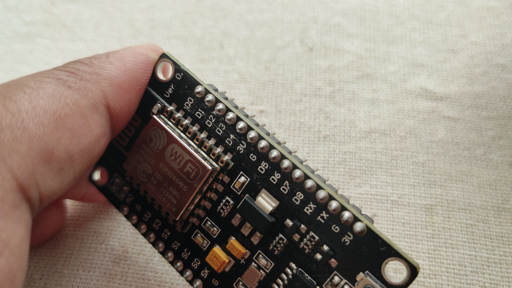
In this project, we will use Quectel L86 GPS Module and interface it with NodeMCU ESP8266 Board. Instead of Quectel L86 GPS Module, you can also use Neo-6M GPS Module or any other similar GPS Module. Using the TinyGPS library, we will determine the latitude, longitude, speed, bearing as well as the location on Map. We will send all these parameters to the Blynk Application and monitor the real-time data along with the map on Blynk Dashboard.
The L86 is an ideal solution for wearable fitness devices due to its ultra-compact design and low power demands. Its Low Power feature enables GPS connectivity at around half the power consumption of normal mode while in static receiving mode. Combined with its precision and high sensitivity, this makes the L86 suitable also for a broad range of IoT applications such as portable devices, automotive, personal tracking, security, and industrial PDAs.
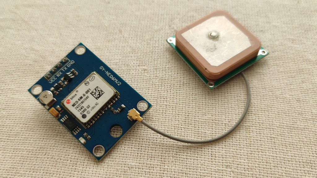
The L86 has a patch antenna on top measuring 16.0mm × 16.0mm × 6.45mm, with 66 acquisition channels and 22 tracking channels. It acquires and tracks satellites in the shortest time even at the indoor signal level. The module operates at 2.8V~4.3V with a typical power consumption of 20mA and in Standby mode power consumption is around 1.0mA. To learn more about the L86 GPS module, you can check the L86 Datasheet.
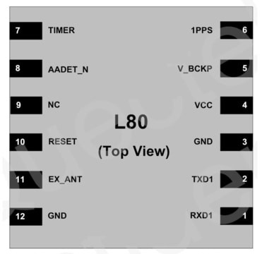
The Quectel L86/L80 GPS Module has 12 pins as shown in the image below.
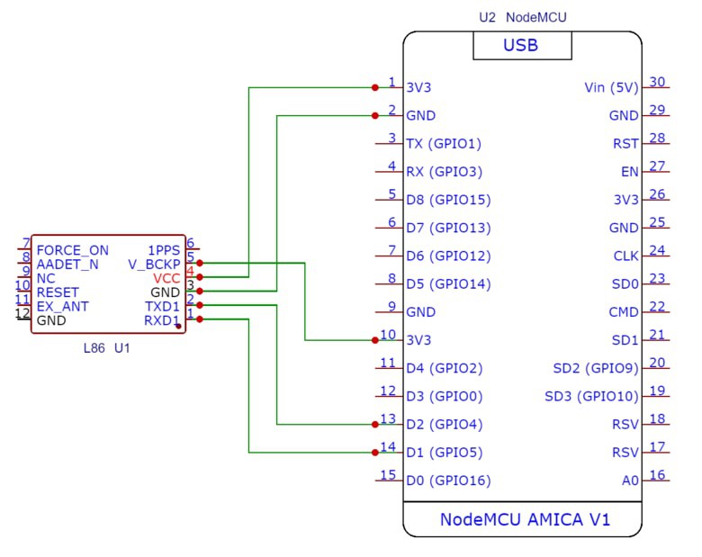
Connect the VCC/GND of the L86 GPS Module to 3.3V/GND of NodeMCU ESP8266. Do not supply more than 3.3V. Similarly, connect the VCC backup (V_BCKP) with VCC or to an external battery. It won’t work if this pin is not powered.
Connect the RX/TX of L86 to the D1/D2 of the NodeMCU. This is for Serial Communication using Software Serial.
What is ESP8266 and how does it work?
ESP8266 is a low-cost WiFi module that belongs to ESP's family which you can use it to control your electronics projects anywhere in the world. It has an in-built microcontroller and a 1MB flash allowing it to connect to a WiFi. The TCP/IP protocol stack allows the module to communicate with WiFi signals. The maximum working voltage of the module is 3.3v so you cant supply 5v as it will fry the module.
Let's take an example of controlling an LED light using ESP8266 by smartphone. The ESP8266 acts as an interpreter between the LED and the smartphone. Since we are using the Blynk app to control the LED further explanations will be based on it.
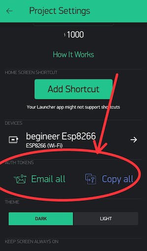
Then scroll down until you see the heading "auth token."
To communicate your ESP8266 with the Blynk app, you have to add a Blynk library to your arduino IDE folder. For that, you need to download the library file from the link below:
https://github.com/blynkkk/blynk-library/releases
Once you have downloaded it, extract the file and copy the folders. Then open your Arduino folder and click on libraries folder. Right click and click on paste button. You have successfully installed the Blynk libraries.

Setting up the Arduino IDE for programming ESP8266
Before programming the ESP8266 in Arduino IDE you have to change the board manager to ESP8266.
If you haven't made any projects on ESP8266 before, you have to follow these...
Read more »
 Michael O'Toole
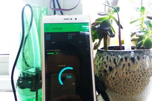
 muzi
muzi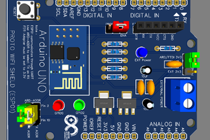
 Mrinnovative
 mit41301