Thursday, 16:41, 15/12/2022
20/12/2022
Sorry for the delay, for some reason my brain refused to work these last 5 days, so I didn't work that much on this project log as I wished to.
23/12/2022
For some reason, it seems like this Project log is so long that the Hackaday website is lagging and bugging, basically, the topics 2 and 3 got deleted, so I will be forced to work on hydraulic accumulators and costs on the next project log.
Just you got an idea, at the end of the project log, the text gets automatically deleted when I add something.
I added what the Project log deleted at Project Log 16.1

I'm putting here all the subjects that I couldn't talk about in Project Log 14:
- Hydraulic pumps and its relation to high pressure artificial muscles. I need to calculate the amount of flow.
My first thought was, like I said in the Project Log 13, using manual hydraulic pumps with electric motors. I thought it was the best option, but the pressure is generated too slowly, so I would need a hydraulic accumulator, and the following reasons will clarify why.
- Hydraulic accumulators.
Basically, one could simply use a cheap 12V tire inflator/air compressor to fill up a bladder hydraulic accumulator. But these are expensive, and I don't know how long a 300 PSI air compressor for tires will take to fill up homemade sketchy bladders. Also, pneumatics are kinda dangerous, they can explode.
Also, one doesn't really neeed bladders, I could simply use a car spring that is pulled by a electric motor. Like a electric jack/linear actuator. When the spring is pulled, the hydraulic oil will be forced in by vacuum action, then I just need to release the spring and the compression of the spring will compress the hydraulic fluid and that's it.
Kinda of, I need to find a way of calculating that. I remember once reading an scientific paper of a "novel design of hydraulic accumulator" or something among these lines, I need to find it again. Maybe they have a model/equation that I can use to guess how much pressure it will generate, if there isn't already an option that I can buy online. For some reason, the electric jack/lineart actuator is more expensive than the hydraulic jack... Bruh.
Found the article: "A novel pump design for an efficient and compact Electro-Hydraulic Actuator IEEE aerospace conference".
No, actually, I think it was this one: "Development of a novel compact hydraulic power unit for the exoskeleton robot".
Or I could simply use a electric jack directly compressing the hydraulic fluid... I could also make a homemade pulley that pulls the hydraulic accumulator spring. Homemade because the fricking electric pulleys use the same 1hp electric motors the high pressure hydraulic pumps use, so... bruh.
Dunno what is the best option, I will need to calculate every single one of these. I hope the people I invited to this project could be able to give me a hand, we probably know as much as each other, but 4 heads think more than 1. - Costs.
I was thinking a little bit here about the overhaul cost of this mech. A single car in Brazil can cost 100,000 Reais, but in the US it costs around 30,000 Dollars (as foretold by google). If we can make this thing under 10,000 Reais (or just 2000 Dollars), doesn't that mean it is actually very cheap to make one in comparisson to cars? hum 🤔 For example, if I used 72 5 ton hydraulic jacks that normally cost 100 Reais (19 Dollars) each, I would be expending 7200 bucks on the actuators alone, more 2000-3000 on the electronic parts including the hydraulic pump. This means this thing would cost kinda okay...? 🤔 (Not okay to me, I'm broke).
Quite the off-topic here, but...

I just love these arts from Theo Stylianides (I took this image directly from their Artstation profile) and I actually often look at their art for inspiration on this project. Like the modularity of their models.
I know that this is "just" a 3D model for a game or a project of sorts, but one thing that I always liked about their arts/models is that even though it is supposedly meant to be "tacticool" or "only" a concept, it reeeeally feels believable. Because these are really boxy and "brute" with "function over shape" design that would definitely be a modular piece of equipment in the real world.
Anyway, all of this tangent just to start a discussion on the subject of:
Maybe I should think on the artificial endoskeleton of the mech in this project to be more like hollow "boxes" as shown in the second part of the artwork above this text instead of metal tubes like the 3D model I've made in Project Log 6 and Project Log 10.
The idea is to make the "skeletal boxes" more or less like the concept above this text, so it would be easier to ask for CNC or cutting shops to "just" print these parts would in a 2D plane, and screw the parts together. It would also be possible to print the 2D design in pieces of papers, glue to metal plates and then "just" cut everything by hand.
The muscles, equipment and wiring would be inside these "boxes", including the pilot, which would be inside a bigger "box".
However, the problem is that it would harder to safely calculate/estimate how much structural tension, force and damage these skeletons would be able to withstand, unlicky predictable and simple tubes. Also, the mechanical advantage of the "levers" in the body must be taken into consideration, the muscles need space to operate because otherwise they wouldn't be able to move the body.
Another problem is that it would be even less safer to be around other humans, not that my first design would be "that" safer either. But at least the exposed muscles would be like cushions with liquid inside that maybe would be easier to stand around instead of solid and sharp edges of metal boxes.
It could be more useful if the "hollow boxes" where the endoskeleton itself, like the hollow metal tubes, which would allow for all the wiring to go through them. But at that point, why not just use the hollow tubes, tho?
Anyway, it would be an interesting military design, but I don't want this to be a military thing, even though mechs are normally meant to be military in sci-fi.
... But thinking better about it, I don't really like screws that much. Because every time I need to disassemble electric motors that were thrown away, I need to use an angle grinder for hours in order to take the damn motor out of its metal compartment.
Literally because the screws get so bent and rusted that they can't be unscrewed normally, so I need to make a huge mess (and damage to the overhaul equipment) just because a single screw is stuck on the fuselage and it is screwing me over.
But nuts and bolts? Now that is the good sh*t.
Too small or too big for your screw driver? Just use a plier. Too rusty? Too bent? Can't be pulled over by a plier? Just cut it, it is not screwed directly to the fuselage, it is not welded on it. You could even hammer it out and just bring a bigger bolt later and keep everything together.
The biggest problem of every equipment, system or whatever is when whoever is building/developing/desinging them aren't considering that this said equipment will fail and will need to be fixed.
Also², for some reason Theo deleted their deviantart account. I put a star on a lot of their works there y-y
Also, I just found this video, it is not related to this project log, but i believe it is very interesting:
Being honest, for some frickery reason, I'm really interested on continuum robots instead of human-like bone-muscle mechs/robots in general.
Don't get me wrong, I (think) won't throw alway all the progress I've made until now just for a random idea I had (like any ADHD person would do), analysing the prospect of working along-side humans, this seems a more safe and useful idea (and maybe cheaper).
If you don't know what a Continuum Robot (or tentacle robot, or trunk robot) is, let me share some videos:
In summary, they are Doc Ock arms, not all of them, but some of them.
/cdn.vox-cdn.com/uploads/chorus_asset/file/22155007/doc_ock.jpg)
I say that because of the obvious differences in structures:
Some have solid spines (like the Doc Ock above) and some don't have spines, like the festo one above.
The problem is that continuum robots are the f*cking hardest to calculate its movement, also known as "kinematics" or "inverse kinematics".
In a normal robot you only need an encoder on the axis of rotation in order to know its position, but how you would do that in a spineless tentacle?

Well, I just had the idea of maybe using a plastic "inner sensor" whenre a bunch of 3D printed rotational articulations with encoders on them would track the entire thing.
For example, just imagine the following continuum robot with its spine's rotational axis with enconders on them:

... Or maybe like a Nintendo 64 joystick.
But wait, how do you lift 1 ton with these continuum robots?
It is easy to calculate with a solid lever (like an arm), but how you do that with a continuum robot?
My idea was to use multiple multifilament steel cables as a spine and a lot of McKibben muscles as muscles.
As shown in the illustration I've made on paint bellow, the idea is to make a central spine and an extra spine to each direction you want the tentacle to move, just like Festo and Doc Ock have 3 lines of segments that each allows for a degree of movement.
And it would partially allow for retraction and expansion of the tentacles, just like Doc Ock does.

I know it is hard as heck to calculate this, but i think it is worth it. I mean, I do want to walk around with a mech and help people lift heavy stuff.
But you know, I don't want to break someone's feet by accident, or even worse, a toddler excited with the robot walking in my blind spot and getting fatally wounded...
I think it is worth the trouble.
And yes, I'm just saying this because I dreamt this happened, I woke up in a cold sweat.
The broken shape of a toddler in the ground scarred in my mind as I woke up...

I really really don't want that to happen.
I will try to calculate this thing on the next project log.
Edit¹:
So, now that a day have passed, let's just say that I calmed down. That dream really messed up my brain.
And maybe I should give up on the idea of continuum robot mech.
For some reason, the hamster in my brain has gone full throttle trying to think in solutions to the "spaghetti body that can't lift 1 ton" problem of spineless continuum robot bodies.
And I couldn't find any.
For example, think of the illustration I've made: if it where to lift 1 ton weight at, let's say, 60 cm of distance from the shoulder, even if all the muscles where fully actuated and tensioned, it would still bend in unpredictable directions.
Because these are cables, how to you stop cables from bending? It is like trying to build a bridge with ropes without connecting both sides.


Now pretend that the rigid horizontal concrete line is just a big rope?
It will act like a giant spaghetti and fall to the ground.
Then I "tried" (in my mind) to imitate the human shape body, adding more cables and rubber/flexible resin, stiffening the limbs and letting the joints flexible, like a compliant endoskeleton.
Imagine it like those plastic hinges on pencil cases:

It is almost solid in most part, but in the point it needs to bend is quite slim. That's the idea.
The problem is that, even if I did that, how I would be able to lift 1 ton at 30 cm in an horizontal line? (you know, like an arm)
All of this would be done to increase stiffness of the structure, but you would innevitably reach such leves of stiffness in order to lift 1 ton, that you would literally become completely solid.
And all the problems would still stay even if I used the suggestion bellow as a basis, because I did use that as a basis.
Maybe I would have better ideas if I made rope 3D models on Blender, but I'm still working on Project Log 16, not on spagetthi project log.
This video of the robotics department of disney is very promising, but, again: in order to lift 1 ton, one would need such amounts of resistance for bending (stiffness), that the structure would eventually be rock solid (or "metal solid", in this case).
And yes, I could use the Festo design of spineless continuum robot, because it is the most promising (for my gut feelings) at being able to lift 1 ton and still be compliant and safe...
However, the muscle needs a lot of space inside of it, space thta needs to be filled with either air or hydraulic fluid.
I would need too fricking much fluid to actuate it, so much that I don't even know if it would be viable.
I don't even know if hydraulic accumulators would be able to supply them.
And yes², I could use some kind of spine/bones with some kind of structure, but I feel that it defeats the porpuse.
Because these "bones" (disks, tubes or spheres) would need to be strong enough to withstand 1 ton or more, and these would be the rigid and hit like a metal chain whip.

Of course, this is just my rationalisation and conclusion, you would probably have a better idea than me.
Edit²:
You know, a good alternative is to look up to Air planes fuselage.
Aerospace engineering is about making the less amount of material to be able to support the biggest amount of stresses and loads.

I would need big ass balloons made of polyurethane all over the mech's body and on the feets...
I think a good start is making "fake" fulcrum points on the limbs, for example, this concept art where the flexible robot has limbs in the middle of the limbs:
The artist's name is "Ben Mauro" on artstation.
Also²³¹², since this new mech design is meant to not break other people's body, doesn't it mean that now it is safe to be used as an exoskeleton?

Enough of tangents! Back to the real topic:
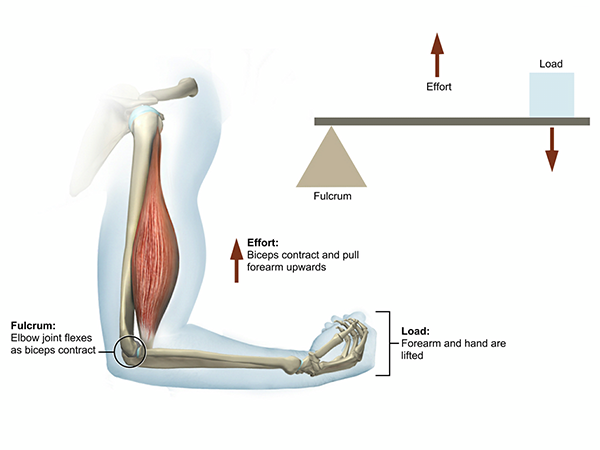
1 - Calculating Hydraulic pumps, Fluid Flow and Fluid Tanks:
And now that I stopped to think about it, how the f*ck do you calculate the amount of liquid required for a hydraulic McKibben muscle?
Well, I actually asked the ChatGPT (an AI that is a Chat Bot and can actually give you complex answers and even code programs for you).
Here is the following conversation:
Me:
Can you tell me how much hydraulic fluid a hydraulic McKibben artificial muscle would require to work?
These normally have a contraction in length in the order of 20% or more, however, one could say that a McKibeen muscle would require a percentage of its initial amount of fluid to contract.
ChatGPT:
Hydraulic McKibben artificial muscles, also known as pneumatic artificial muscles (PAMs), are used as actuators in robotics and other mechanical systems. They are typically made of a flexible, elastic material that is surrounded by a braided outer layer. When pressurized with a fluid, such as air or oil, the muscle expands and contracts, allowing it to lift and move objects.
The amount of fluid required to operate a hydraulic McKibben artificial muscle will depend on a number of factors, including the size and shape of the muscle, the type of fluid being used, and the amount of pressure required to produce the desired movement. In general, these muscles tend to require relatively small amounts of fluid compared to other hydraulic systems, as they rely on the elastic properties of the material to generate movement rather than large volumes of fluid.
It is difficult to give a specific answer as to how much fluid a McKibben muscle would require, as it will depend on the specific application and the specific muscle being used. It is generally recommended to start with a small amount of fluid and gradually increase it until the desired movement is achieved. It is also important to ensure that the fluid level is maintained at the appropriate level, as running the muscle dry can cause damage.
Me:
Let's say, a McKibben muscle with 30cm of length, 5cm of radius. The density of the hydraulic oil is 0.9g/ml, and inside this muscle the oil has 2.3 liters of volume and 1.88 kg of mass.
In order to contract it by 20%, how much fluid I would require?
ChatGPT:
To determine the amount of fluid required to contract a McKibben muscle by a specific percentage, you would need to know the characteristics of the fluid, such as its density and viscosity, as well as the size and shape of the muscle, including its length and radius. You would also need to know the desired amount of contraction, in this case 20%.
Based on the information provided, it appears that the McKibben muscle you are considering has a volume of 2.3 liters and a mass of 1.88 kg, and that the hydraulic oil used has a density of 0.9 g/ml. However, it is not clear how these values are related to the size and shape of the muscle or the desired amount of contraction.
Without more information, it is not possible to accurately calculate the amount of fluid required to contract the muscle by 20%. It is generally recommended to start with a small amount of fluid and gradually increase it until the desired movement is achieved, taking into account the specific characteristics of the muscle and the fluid being used. It is also important to ensure that the fluid level is maintained at the appropriate level, as running the muscle dry can cause damage.
Me:
What informations you would need in order to give a complete answer? Could you list them for me?
ChatGPT:
In order to accurately calculate the amount of fluid required to operate a hydraulic McKibben artificial muscle, I would need the following information:
- The size and shape of the muscle: The length and radius of the muscle would be important in determining its volume and the amount of fluid required to fill it.
- The characteristics of the fluid: The density and viscosity of the fluid would affect how much of it is required to produce a given amount of movement.
- The desired amount of contraction: Knowing the desired amount of contraction would allow me to calculate how much fluid would be required to achieve it.
- The pressure required to produce the desired movement: The amount of pressure required to produce the desired movement would also need to be taken into account in order to accurately calculate the amount of fluid required.
- The specific application: The specific application in which the McKibben muscle will be used may also affect the amount of fluid required, as different applications may have different requirements for movement and pressure.
It is generally recommended to start with a small amount of fluid and gradually increase it until the desired movement is achieved, taking into account all of these factors. It is also important to ensure that the fluid level is maintained at the appropriate level, as running the muscle dry can cause damage.
Me:
1 = The shape of the muscle is a cylinder. The size is 30cm of length and 5cm of radius.
2 = The density of the hydraulic fluid is 0.9 ml/g and the viscosity of the fluid is 32 on ISO viscosity grade.
3= The desired amount of contraction is 20%.
4 = The pressure required is 0.8 MPa, or 116 PSI of pressure.
5 = The application is for the muscle to lift weight linearly in the vertical.
Based on the information you provided, the size and shape of the McKibben muscle is a cylinder with a length of 30 cm and a radius of 5 cm. The density of the hydraulic fluid is 0.9 g/ml, and the viscosity of the fluid is 32 on the ISO viscosity grade. The desired amount of contraction is 20%, and the pressure required to produce this movement is 0.8 MPa, or 116 PSI.
To calculate the amount of fluid required to achieve the desired contraction, we can first determine the initial volume of the muscle. The volume of a cylinder is given by the formula:
V = πr^2h
Where V is the volume, r is the radius, and h is the height (length) of the cylinder. Plugging in the values for the radius (5 cm) and height (30 cm) of the McKibben muscle, we get:
V = π(5^2)(30) = 706.9 cm^3
Next, we can determine the volume of the fluid required to achieve the desired contraction of 20%. The volume of the contraction can be calculated using the following formula:
V = V0 * (1 - (d/100))
Where V is the volume of the contraction, V0 is the initial volume of the muscle, and d is the desired percentage of contraction. Plugging in the values for the initial volume of the muscle (706.9 cm^3) and the desired contraction (20%), we get:
V = 706.9 * (1 - (20/100)) = 565.5 cm^3
Finally, we can use the density of the fluid (0.9 g/ml) to calculate the mass of the fluid required to produce the desired contraction. The mass of the fluid can be calculated using the following formula:
m = d * V
Where m is the mass of the fluid, d is the density of the fluid, and V is the volume of the contraction. Plugging in the values for the density of the fluid (0.9 g/ml) and the volume of the contraction (565.5 cm^3), we get:
m = 0.9 * 565.5 = 508.95 g
This is the mass of fluid required to produce the desired contraction of 20% in the McKibben muscle. It is generally recommended to start with a small amount of fluid and gradually increase it until the desired movement is achieved, taking into account the specific characteristics of the muscle and the fluid being used. It is also important to ensure that the fluid level is maintained at the appropriate level, as running the muscle dry can cause damage.
I f*cking love this AI.
(this would be 0,6 liters, by the way, so, in total, I would need 43.2 liters (36.6 kg) of hydraulic fluid to activate all of the muscles at once)
However, let's not get ahead of ourselves, I know that I relied myself upon this chatbot too much, and like any other AI, it can commit mistakes.
So I will try to find out by myself, and then get back here and check out if the AI is correct.
Well, I couldn't find a f*cking simple answer (as always), but I did find this article where they show what the inner bladder is made of:
The article is "Bioinspired hydraulic McKibben actuation for efficient robotic motion: energetics, variable recruitment, and control".
It is just a plastic bag of LDPE (Low-density polyethylene).

By the way, accordingly to the article, this kind of inelastic bladder, where it is almost glued to the braided sleeve, is actually better to achieve contraction.

Although I think they're cheating here, because the first muscle doesn't have the same length as the other 2.
Yes, I do believe such muscle would be able to withstand 5 tons, you just need to make the inner bladder longer than the braided sleeve, so the braided sleeve made of aramid will take all the weight.
I do want to change the materials of the inner bladder, because I feel this is still just too fragile and simple.
But I don't know how I would be able to make it better, though... Maybe I should stay with the flat hose thingy as the bladder like I talked on Project Log 12? humm... 🤔
The fluid flow rate:
Well, I should've had at least double-checked the equation the own AI showed me:
V = πr^2h
Where V is the volume, r is the radius, and h is the height (length) of the cylinder. Plugging in the values for the radius (5 cm) and height (30 cm) of the McKibben muscle, we get:
V = π(5^2)(30) = 706.9 cm^3
Next, we can determine the volume of the fluid required to achieve the desired contraction of 20%. The volume of the contraction can be calculated using the following formula:
V = V0 * (1 - (d/100))
Where V is the volume of the contraction, V0 is the initial volume of the muscle, and d is the desired percentage of contraction. Plugging in the values for the initial volume of the muscle (706.9 cm^3) and the desired contraction (20%), we get:
V = 706.9 * (1 - (20/100)) = 565.5 cm^3
Shouldn't the volume increase, but sideways?
So, assuming it decreases in length by 6cm (20% in length contraction) and the diameter, as shown in the article pictures I showed before, their diameter increases by more or less 1cm
So:
- V = π(5.5^2)(24)
- V = 2280.79
No, wait, let's check the first equation:
- V = π(5^2)(30)
- 2356.19 (in "Radian" or "Degree" mode on the calculator).
So... Uh... I guess the chatbot missed the mark? lol
Bruh, this makes me think that maybe that Mckibben Force Calculator I asked the chatbot to make is waaay off...
Or not, I didn't ask it to actually calculate anything, just to code the calculation... Who knows...
Anyway, the difference between these two volumes is 75.3.
m = d * V
Where m is the mass of the fluid, d is the density of the fluid, and V is the volume of the contraction. Plugging in the values for the density of the fluid (0.9 g/ml) and the volume of the contraction (565.5 cm^3), we get:
Well, let's see...
- 0.9 g/ml x 75.3 Cm³
- 67.77 g
- this would be 0.0753 liters.
In order to achieve full contraction of all the muscles, I would need 5.5 kg of hydraulic fluid or 5.4216 liters.
5 liters can be achieved by any kind of pump... If this was liters per minute.
I need to actuate these in a third of a second, so even though these only need in total 5 liters, I need 3 times that value per second of fluid speed. In this case, 0,015 cubic meters per second or 900 liters per minute. Which is not possible for any hydraulic pump.
But it is for hydraulic accumulators.
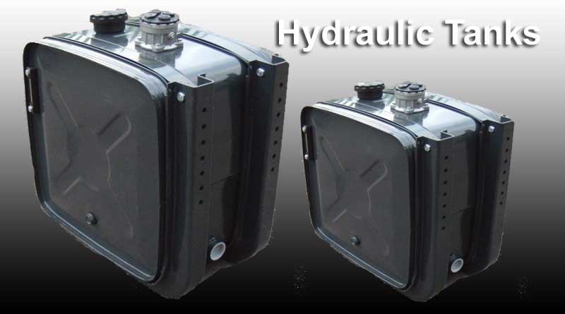
The fluid tank:
I'm reading this article here with the title: "How To Size A Hydraulic Tank", if it is useful, y'all will see it in this project log (because I didn't delete this part).
"The rules of thumb for reservoir size differ for open and closed circuits. For a conventional reservoir used in open circuits the general rule is a tank oil capacity of 3 to 5 times the flow of the pump(s) per minute plus a 10 percent air cushion. For HFC and HFD fire-resistant fluids the general rule is 5 to 8 times pump flow per minute.".
Well, I don't like where this is going...
If I were to size my hydraulic tank like that, I would need 2700 to 7200 liters of hydraulic oil, but I don't need all that fluid, simply because I know how much fluid in total I need.
I would just need a 15 to 20 liters of hydraulic oil in a tank, and maybe more than that, since almost all the oil would be on the hydraulic accumulators.
I guess that I will need to size the tank based on the size of the hydraulic accumulators amount of fluid.
However, I don't need to activate all muscles at once, and I can simply use an Hydraulic Accumulator with a slower pump.
The hydraulic pump:
Normally hydraulic pumps (just the pump, not the eletric motor) on horse power per pressure, like, it will produce 50 bar with 4 horse power of force on the shaft. Nothing about
1 horse power = ± 75kg of torque.
I would basically need two 35 kgf/cm stepper motors that normally costs 300 Reais each, but there is also stepper motors with 120 kgf/cm that costs around 1000 Reais or such.
I mean, it doesn't need to be stepper motors, It just these are the first ones that normally appear when I search on google.
The direct current ones or with reduction gears would do just fine doing the same thing, however, at lower speeds and lesser energy consumption.
Another note is that all the hydraulic pumps that I can find are normally either separated or just stuck too close to the electric motor, which wouldn't be a problem in a conventional hydraulic system.
But we are using magnetoheorlogical hydraulic fluid, a fluid that changes its viscosity in the presence of magnetic fields.
So I need to think extra hard when the subject is Faraday Cages to protect the fluid from the electromagnetic fields that are formed outside of the cables.
So, since no hydraulic pump is cheap, nor simple, I was thinking on make one by hand with off the shelf materials.
Like with those big syringes for food/oil with one way valves inserted on them (these can also be used *for other things*, but this isn't a enfermary project log, lol).


Like in the example above.
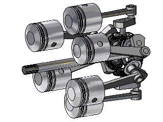
I also thought on using conventional designs from conventional combustion engines:

Like this 3D printed radial engine.
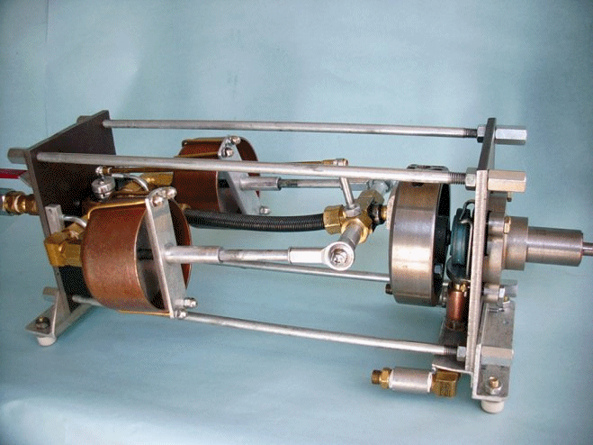
Or like those weird axial engines:
This is called Dynacam aero engine.
I know that this is called "Trebert Axial Engine", it is from the 1910's.
I just found this one, it is called "Green Steam Engine", it seems like it is the simplest axial design I could find. Since most axial engines have a swash plate to drive the pistons.
However, what is driving the pistons that drive the disk is steam, not the disk that is actuating the pistons.
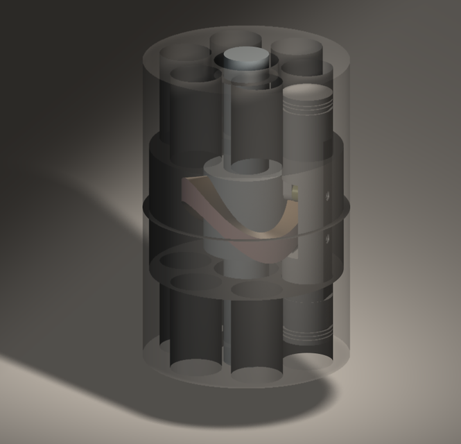
There is a lot of designs for "barrel engines", lol
From article: "The Potential of Wobble Plate Opposed Piston Axial Engines for Increased Efficiency".
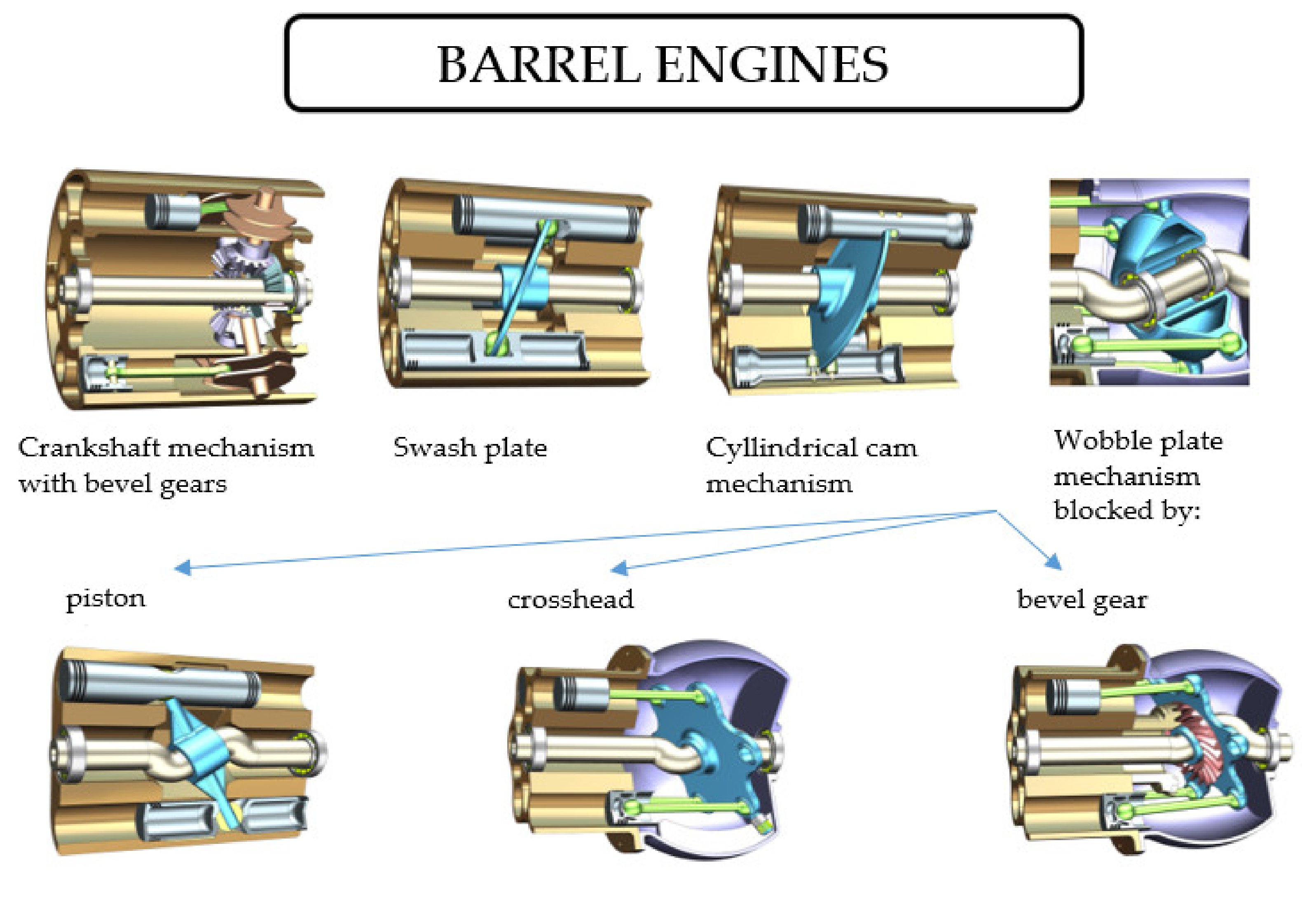
Of course, I won't make them out of metal or such, just 3D printing these. For example, the Dynacam could easily be 3D printed and then fitted with bearings.
Actually, I kinda prefer the axial engines becase they are more compact, the radial one would be like a big disk with a cylinder on the horizontal (the electric motor) sticking out of it. It would be vulnerable to impact.
Now an axial pump, would be like a continuous cylinder that could be attached to the mech like a rolled sleeping bag.
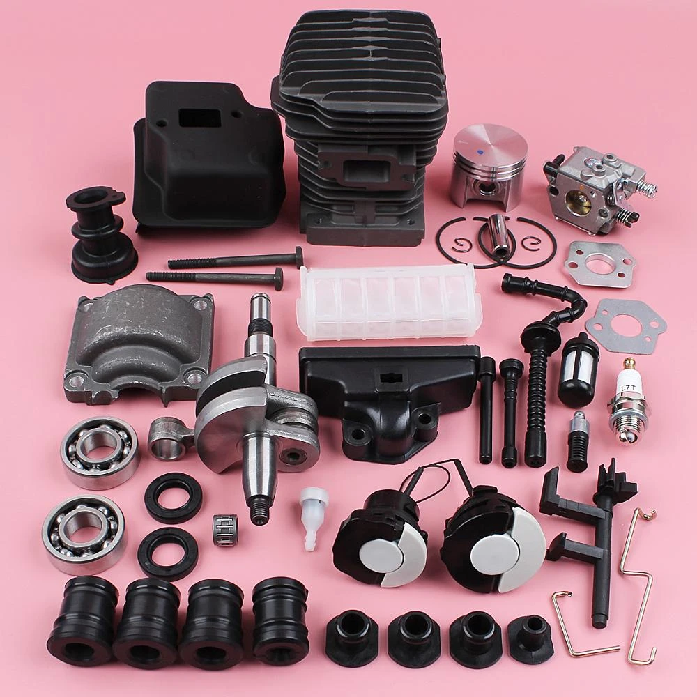
I could also use actual combustion engine crankshafts as adapted hydraulic pumps, I mean, these can withstand combustion explosions, why not some hydraulic oil?
As you can see bellow, it is a single piston bicycle engine with all the equipment one would need. I really don't need the spark plug and almost half of the stuff in the image. but it feels complete enough.
Also, these costs like, 400 Reais each (75 dollars). Not very cash money for a 10-20 cylinder axial pump.
Well, it took me a really long while to find it, but basically, if you search only for small pistons, single cylinder crankshaft and "engine cup" or "cylinder liner" and the following results will appear:

The pistons and the single cylinder crankshaft are like, 50 bucks, the cylinder liner is another story, but it is "just" a metal tube, right? I think I could improvise with that.
Anyway, back to the syringes:
First, I would need to find a way to either make a piston pump from plastic syringes without the rubber part, or use glass syringes (that can break).
As you can expect, the rubber creates a lot of friction during the movement of the piston. I could, maybe, attach a membrane to the piston instead of the rubber sealing.
But I have no idea how I would do that without weaken the membrane itself, and if I where to actually modify the syringes that much, I would be better just using metal tubes with a membrane.
The glass syringes have such small margins of error that they are literally air tight.
And funny enough, these are surprisingly cheap, cheaper than the plastic ones in some cases. And these wouldn't need any kind of modification, the friction would be (almost) negligible.
The problem is that these are made of glass... Even though some suppliers say they are made of borosilicate, it is hard to tell how well these would endure, since these are meant for medical usage, not hydraulic pumps.
(I tried to search for metal ones, but those also have rubber seals)
I have totally forgot about those air springs (or "gas strut") for kitchen/furniture/cars, which are cheap and could easily be modified to work as hydraulic/pneumatic cylinders or piston pumps.
The only problem is that I have absolutely no idea how much pressure these can withstand, meaning I would need to personally test these out (or just ask on quora, maybe this time people won't call me stupid).
Here is a short 4 minute video showing the process.
These "air springs" (or dampers) are ranged on values of newtons, like 100 Newtons, 200 Newtons, 500 Newtons (around 50 kg) and so on. It is the amount of weight these can lift out of the factory.
Once I heard that this simpler one shown in the video above could withstand around 150kg.
And, as you can see, the fricking piston has a hole on it, so you need to also take care of that. But it is beyond me how the guy in the first video didn't experience any leak.
It would help a lot if the sellers and suppliers of these gas springs actually listed the amount of pressure inside these cylinders...
I just found this link that says these normally have 150 bar or more.
150 bar = 15 Mpa = 2175 PSI
In this video the guy kinda addresses that hole on the piston:
Too much work, but hey, these are the only cheap options that would definitely withstand the forces in a hydraulic pump...
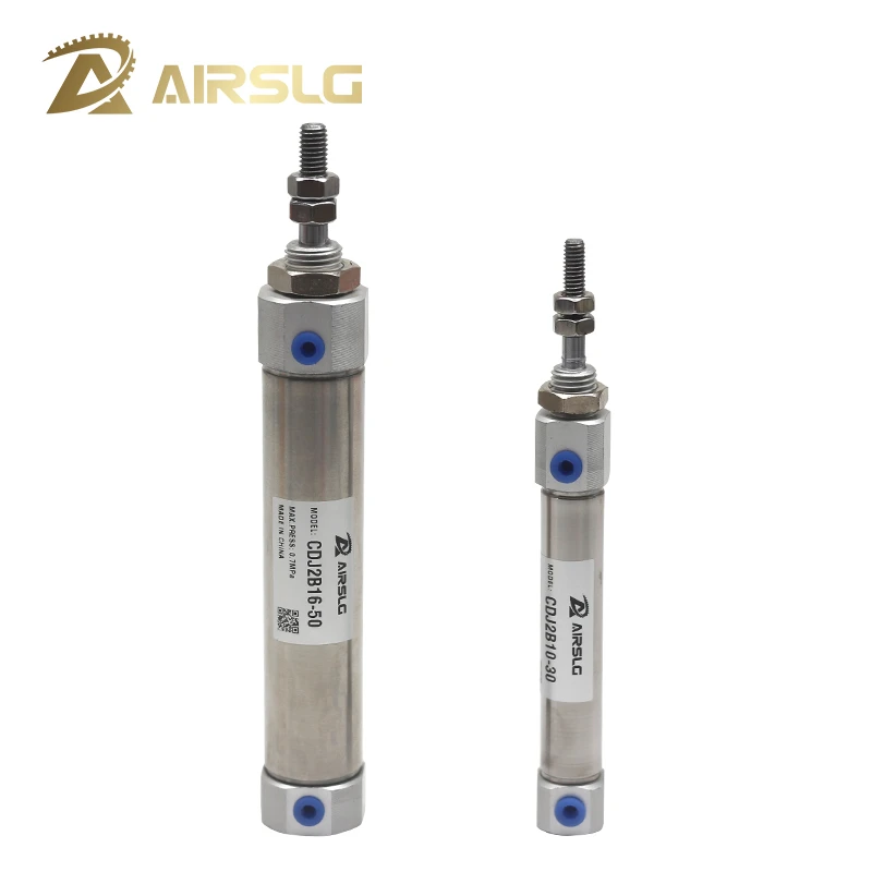
Well, I guess it would be easier if I simply used the fricking cheap (as cheap as the gas struts) pneumatic cylinders that are already easy to find anywhere...
Why I always go in the biggest tangent ever just to arrive at the most simple answer possible?
But wait...
Do I really need a single pump and a hydraulic compressor?
Each muscle needs around 0.07 liters to actuate, 0.21 liters per second or 2.1 liters per minute. A lot of hydraulic pumps can achieve that...
Nah, forget it, each pump costs 400 reais (80 dollars), I just looked it up. Just imagine paying that for 72 pumps, bruh.
And that's for RC pumps, the real pumps are more expensive.
Also, aliexpress loves tricking me into thinking the products are cheaper, by shown the costs of the cheapest option of the product, that normally is just the cables.

"Discount for new users", heh, as if.
If these were way cheaper, maybe I wouldn't need hydraulic accumulators or solenoid valves...
And yes, I could use other smaller pumps, but those can't produce enough pressure.
For example, peristaltic pumps are the best candidate, but I don't know how much pressure they can produce, if they can produce at all.
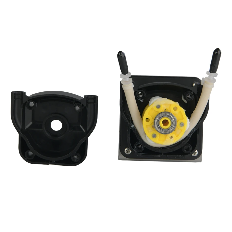
In this one, it was said it achieve 200ml per minute, not enough to actuate a muscle in a second, but hey, I would need smaller hydraulic accumulators.
The only problem is that I don't know how to calculate these pumps, how much flow these would generate and how much pressure they would also generate, neither how much torque the driver motor would need.
Oh well, I think I will ask to the Chat Bot again. lol
Me:
Is in your knowledge to be able to tell me how much hydraulic oil flow and pressure an electrically driven piston hydraulic pump would generate at a given kilogram force of torque?
Chat GPT:
It is possible to estimate the flow and pressure of a hydraulic pump based on its torque rating and displacement, but there are many factors that can affect the actual performance of the pump, including the efficiency of the pump, the resistance of the load, and the speed at which the pump is operated.
To estimate the flow and pressure of a hydraulic pump, you can use the following formulas:
Flow (liters/minute) = pump displacement (cm^3/rev) * pump speed (rev/minute) / (10^6 cm^3/liter)
Pressure (bar) = torque (kg-force * m) / (pump displacement (cm^3/rev) * pump efficiency)
Keep in mind that these formulas are only rough estimates, and the actual performance of the pump may differ significantly from these estimates. It is best to consult the manufacturer's specifications or conduct testing to determine the actual flow and pressure of the pump.
Me:
If you allow me to ask, how the calculation of the pump displacement is made? It is the surface area of the piston, or the entire chamber?
Chat GPT:
Pump displacement is a measure of the volume of fluid that is displaced by the pump's pistons in a single revolution. It is typically measured in cubic centimeters per revolution (cm^3/rev).
To calculate the pump displacement, you can use the following formula:
Displacement (cm^3/rev) = π * r^2 * s * n
Where:
π is the mathematical constant pi (approximately 3.14159)
r is the radius of the pump's piston(s)
s is the stroke length of the pump's piston(s)
n is the number of pistons in the pump
For example, if a pump has a single piston with a radius of 5 cm and a stroke length of 10 cm, its displacement would be approximately 157 cm^3/rev (π * 5^2 * 10 * 1).
It is important to note that the displacement of a pump is not the same as the volume of the pump's chamber. The displacement refers to the volume of fluid that is displaced by the movement of the pump's pistons, while the volume of the chamber refers to the total volume of the space inside the pump.
Me:
I see, thanks for the help
Chat GPT:
You're welcome! I'm glad that I could help. If you have any more questions, feel free to ask.
Me:
In the hydraulic pump fluid flow you don't take fluid viscosity and density into account, if possible, could you tell me how it would these two factors would change the equation?
Chat GPT:
Fluid viscosity and density can both have an impact on the performance of a hydraulic pump. Viscosity is a measure of a fluid's resistance to flow, while density is a measure of the mass of a substance per unit of volume.
In general, a higher viscosity fluid will require more force to flow through the pump and may result in lower flow rates, while a lower viscosity fluid will flow more easily and may result in higher flow rates. Similarly, a higher density fluid will require more force to flow through the pump and may result in lower flow rates, while a lower density fluid will flow more easily and may result in higher flow rates.
To account for the effects of viscosity and density in a hydraulic pump, you can modify the flow rate equation as follows:
Flow rate (liters/minute) = (pump displacement (cm^3/rev) * pump speed (rev/minute) / (10^6 cm^3/liter)) * (viscosity (cP) / density (kg/liter))
Where:
viscosity (cP) is the viscosity of the fluid in centipoise (cP)
density (kg/liter) is the density of the fluid in kilograms per liter (kg/liter)
Keep in mind that this modified equation is still only a rough estimate, and the actual flow rate of the pump will depend on a variety of factors, including the efficiency of the pump, the resistance of the load, and the speed at which the pump is operated. It is best to consult the manufacturer's specifications or conduct testing to determine the actual flow rate of the pump.
Me:
How much pressure that equation will produce? Can it be added to the equation?
Chat GPT:
The pressure produced by a hydraulic pump is influenced by a variety of factors, including the pump's displacement, efficiency, and the torque applied to the pump. To estimate the pressure produced by a hydraulic pump, you can use the following formula:
Pressure (bar) = torque (kg-force * m) / (pump displacement (cm^3/rev) * pump efficiency)
This formula takes into account the pump's displacement and efficiency, which are important factors that affect the pressure produced by the pump. However, it does not take into account the effects of fluid viscosity or density, which can also have an impact on the pressure produced by the pump.
To account for the effects of viscosity and density on the pressure produced by a hydraulic pump, you can modify the pressure equation as follows:
Pressure (bar) = (torque (kg-force * m) / (pump displacement (cm^3/rev) * pump efficiency)) * (viscosity (cP) / density (kg/liter))
Where:
viscosity (cP) is the viscosity of the fluid in centipoise (cP)
density (kg/liter) is the density of the fluid in kilograms per liter (kg/liter)
Again, keep in mind that these equations are only rough estimates, and the actual pressure produced by the pump may differ significantly from these estimates. It is best to consult the manufacturer's specifications or conduct testing to determine the actual pressure produced by the pump.
Sorry if I sound too... Rigid? During the questions I make to the chatbot. I'm just trying to be clear as possible and polite as possible.
Like, I will probably start asking questions to other people eventually, so I don't want to sound rude when eventually asking to real people.
Luckily, this time I could find a easy answer to check if the equation is right, however it only shows how stoopid I am, because I could simply searched for "hydraulic pump flow calculator" instead of "how to calculate fluid flow of hydraulic pump" and waste 2 hours watching useless videos on youtube.
Well, calculation time:
So, I will use the pneumatic cylinder dimensions as a basis for the hydraulic pump (just like as I said before).
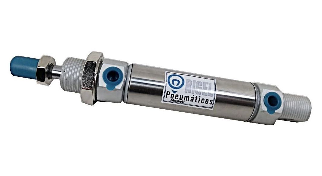
I will calculate the amount of hydraulic fluid flow generated by a single cylinder with two way (meaning it produces more or less the same amount of flow when going forward and backwards).
Accordingly to the Aliexpress ad I chose, this one has a 50mm stroke (the piston moves 50mm in both directions), with a 16mm inner bore and 18mm outer bore (if I didn't read it incorrectly).
It says it was tested with pressures of 1 MPa and an operating pressure of 0.06 MPa.
Displacement (cm^3/rev) = π * r^2 * s * n
Where:
π is the mathematical constant pi (approximately 3.14159)
r is the radius of the pump's piston(s)
s is the stroke length of the pump's piston(s)
n is the number of pistons in the pump
For example, if a pump has a single piston with a radius of 5 cm and a stroke length of 10 cm, its displacement would be approximately 157 cm^3/rev (π * 5^2 * 10 * 1).
To account for the effects of viscosity and density in a hydraulic pump, you can modify the flow rate equation as follows:
Flow rate (liters/minute) = (pump displacement (cm^3/rev) * pump speed (rev/minute) / (10^6 cm^3/liter)) * (viscosity (cP) / density (kg/liter))
Where:
viscosity (cP) is the viscosity of the fluid in centipoise (cP)
density (kg/liter) is the density of the fluid in kilograms per liter (kg/liter)
Pressure (bar) = torque (kg-force * m) / (pump displacement (cm^3/rev) * pump efficiency)
Pressure (bar) = (torque (kg-force * m) / (pump displacement (cm^3/rev) * pump efficiency)) * (viscosity (cP) / density (kg/liter))
Where:
viscosity (cP) is the viscosity of the fluid in centipoise (cP)
density (kg/liter) is the density of the fluid in kilograms per liter (kg/liter)
Well, just now I noticed that the pump equation the bot showed and the one in the hydraulic pump calculator I linked above are for conventional geared hydraulic pumps, but I will try to calculate the bot's equation first and then use the triangle equation of Force, Pressure and Area for cylinders.
By inputing the force of the motor and the area of cylinder, maybe I can get a certain amount of pressure and/or cubic volume that is being circulated.
So, let's calculate for real this time:
- (cm^3/rev) = π * r^2 * s * n
- r = 0.8 cm
- s = 5 cm
- n = 10 (it is actually 5, but as I said: they also produce flow when they are pulled).
- π x 0.8² x 5 x 10
- cm³/rev = 100.530964915
Now taking viscosity into account:
- Flow rate (liters/minute) = (pump displacement (cm^3/rev) * pump speed (rev/minute) / (10^6 cm^3/liter)) * (viscosity (cP) / density (kg/liter))
- Cm³/rev = 100.530964915
- Rev/Min = 1000 (this is normally the maximum speed of a stepper motor, these can reach 6000 or more depending on the motor).
- cm^3/liter = 10 cm3 (I don't know if this is the right value, I just calculated how much liquid would be inside the piston and converted to cm³).
- viscosity (cP) = 32
- Density (kg/liter) = 0,9
- 100.530964915 x 1000 / (10^6(10) x 32 / 0.9
- 0.3574434308
- There must be something wrong. Why the heck I need to multiply cm³ by 10^6?
- 100.530964915 x 1000 / 10 x 32 / 0.9
- 357443.430808
- Whatever, I will take the hydraulic pump calculator into account.
Taking the hydraulic pump calulator and inserting these numbers, it gave me 90.4 l/min and 3-4 bar (0.4 MPa, the value we are looking for) for a single piston of these.
But... If this was 10 pumps, then it would be 900 l/min, exactly the value we need? I feel like there is something wrong.
Probably because the torque will change once all the pistons are connected to the same rotational shaft...
Correcting here:
Yes, it is true that these kinds of stepper motors can achieve 1000 rpm, but that is irrelevant.
When you increase the speed of rotation, you decrease the torque (I think). So even though the motor can achieve such rotation, it wo
Discussions
Become a Hackaday.io Member
Create an account to leave a comment. Already have an account? Log In.
I was wondering if I should have suggested Doc Oc arms for the past week, but then I thought about the amount of actuators and the unsolved question of controlling them so I didn't. I was thinking of arms around a hoola-hoop so that there's an option for 2 - 4 arm walking.
(I should mention that I'm commenting before even reading the whole thing)
Are you sure? yes | no
"The idea is to make the "skeletal boxes" more or less like the concept above this text, so it would be easier to ask for CNC or cutting shops to "just" print these parts would in a 2D plane, and screw the parts together"
So something like the boxes that hold the trusses together in [https://hackaday.io/project/187059-bloft-mk2-3d-printer-for-plastic-waste/details]?
Are you sure? yes | no
Yeah, just like that. :)
Are you sure? yes | no
"Also², for some reason Theo deleted their deviantart account. I put a star on a lot of their works there y-y"
My brother deleted his account too. Apparently a lot of people are scrubbing their artwork from the internet to prevent that art generating AI from using it as source material.
"In a normal robot you only need an encoder on the axis of rotation in order to know its position, but how you would do that in a spineless tentacle?"
I think elephants are the best natural example. They can do very precise work with their trunk. And study your own tongue :) It does seem very difficult.
I don't think continuum legs would make it much safer anyway, since the biggest danger is getting stepped on. The total weight is all that really matters there. It could help when moving a lifted leg, but I think you could do just as well with other methods. Put some padding on the legs, and make them as lightweight and low friction as possible. That way they can be lifted and accelerated/decelerated by gentle force, and won't have too much momentum if they run into something. Give it a "slow and careful" mode that limits the applied torque when the foot is off the ground so it will stop if it bumps into something instead of pushing through it. Then walk carefully, making sure you're well balanced throughout the motion incase you hit anything or need to stop suddenly. Basically like driving a car in a crowded area, or walking in a butterfly house.
Are you sure? yes | no
I see, that is a very good suggestion :)
Also, it seems that Theo (and many others) is deleteding their Artsation account because of the same problem of AI companies stealing people's artwork to be used in the data bases for AI art.
Are you sure? yes | no