18/04/2023, 18:26, Tuesday.
___________________________________________________________________________
PS:
I actually was going to make a 3D model of the stuff, I tried a couple of times and I don't feel like I'm actually putting any kind of effort on it.
It has been a week or something, but I feel like I'm just procrastinating...
I will try it tomorrow or whatever, but I feel like this project log already gives a solid idea on what I should do.
I guess I'm just lazy...
My mood every day be like:

(I'm not actually sad with the project itself, I'm actually kinda revigorated with the recent progress, I just don't know what it got to me right now)
___________________________________________________________________________
So... Uuuuuh... Good afternoon, I guess?
Well, I made up my mind: no unproven designs like the electromagnets made out of electrical transformers sheets.
Electronic protectors have one of these inside themselves, and I found a couple of broken ones in my house.
I took like, two hours and almost bent all of them by simply taking then apart. These are so thin that sometimes they bent by simply falling on the ground.
Still usable tho, but I don't trust myself to build an entire electric motor with high efficiency and power.
I mean... I think I could build one, but a good one? I don't think so.
Counterbalancing Springs:
By the way, I just now remembered about counterbalancing springs on industrial robots.
Basically, a counterbalancing spring is a mechanism that supports the weight of the entire robot, so it only has to produce torque for lifting the payload and fighting inertia on abrupt motions.
So, basically, if the robot was to be slower, it would only consume half as much power, since half the power and torque requirement is to lift its own 1000kg weight, then... It one could cut its energy consumption and torque requirement by half.
... But I doubt it, it easier to counterweight a light robotic arm in a solid and stable base.
(I didn't finished watching by the way)
...I think I finally understood how these springs work (I finished watching it).
The springs are meant to only counterbalance the weight of the robotic arm itself on its highest load capacity instead of any situation no matter the position.
So... It is not ideal for other uses, like a walking robot. It is only capable to sustain its own weight, not to dynamically change its counterbalancing on real time.
Of course, it is not that simple.
How to counterbalance an entire fricking humanoid mechanism?
If it was, then we would already be seeing passive exoskeletons where the entire weight of the body is absolutely supported by the exosuit.
Which is not the case.
So, yeah, what I previously wrote must be incorrect or simply wishful thinking.
I just now remembered the "leg on air" problem (it is not a real name btw, lol).
Basically, if you counterbalance a single leg of the robot for the weight of the entire body, what will happen when this counterbalanced leg lifts off the ground and doesn't has any loads on it?
The 2 tons counterweight will simply go "boing-oin-oing" and pull the entire leg to its direction.
Not to mention that once you divide the weight of the entire body between two legs, the counterbalancing spring will be weaker when the entire weight of the body is under only one leg...
One would need a real-time counterbalancing system that changes its load capacity.
And the only system that I can think of is a pneumatic system, because I really can't see a spring changing its load unless it is mechanically.
A good way to start looking into this system would be quasi-passive exoskeletons.
I remember seeing something like this...
Found it:

"Exobuddy - A Non-Anthropomorphic Quasi-Passive Exoskeleton for Load Carrying Assistance".
It was said in the article (I looked at it using Sci-hub) that they achieved a 30-40% diminishment in the effort required to walk.
Well, not 50%, but a cool amount nevertheless.
However, as you can see by the image itself, it doesn't look like a simple work to achieve...
I was thinking on having a tank with pneumatic or hydraulic accumulator linked to each gas spring (or individually for each gas spring) using a spring as the compressor/pressurizer in the accumulator, with everything with the equal pressure.

So, when the limb needs to move, a solenoid valve opens up and allows air to pass through to the accumulator, when the limb is going to stay still or absorb an impact, the solenoid closes up.
The air will move in and out of said accumulator due to the effort of the electric motors, if it is going to help or stop the electric motor will be a matter of controlling the opening and closening.
Of course, you would need to program it, and I would do it in the simplest way possible (like, "open valve X when electric motor Y moves clockwise"), so I doubt I would be able to achieve 40% less load on each limb.
Besides, like I said before, it will require extra energy for abruptely change the direction of said limb. But... I will try to make it as light as I possibly can, using even densified wood and epoxy.
Yes, you could add compression springs/hydraulic dampers on the feet of the mech and so on in order for it to absorb the change in direction and then, finally adding the force of the actuators.
However, it would still be interesting to have the last resort of using some extra torque from the electric motors to avoid the worst scenario possible. You could also overload your actuators and pass more energy than it is supposed to receive at the risk of damaging it, but I digress.
Although a change from 6kw (8hp) electric motors to 3kw (4hp) electric motors would be welcoming to my wallet, lol.
Of course, I would need to go designing limb by limb, screw by screw.
And that's why I made this Project Log. I need to start first and then go from there.
Wrist-Hip-Ankle-Torso-Shoulder robotic joint (WHATS joint):
So, like I said in previous Project Logs, I will try to use the same mechanism in all parts of the body of the mech, so it is easier to build it and build extra parts.
Because, in the end, if you use the same electric motor, joints and limbs on everything, you won't need to build costumized/unique parts.
So... Why the "WASH joint" thingie?
Because a Wrist is a joint with 3 degrees of freedom, an Ankle is also a DOF joint (ok, not the human ankle, it can only rotate on 2 axis and barely on a third one [unless my leg is messed up]), the Torso and the Shoulder is actually a 5 degree of freedom joint (because in a 6DoF parallel mechanism, like the Stewart platform, you can go up and down on its own axis, unlike our shoulder), so it is basically two wrist/ankle/hip joints facing eachother.

Here a visual explanation of what a "degree of freedom" is. When someone says "X number degrees of freedom", it is a robot that has a movement on one or more axis shown above.
You could make a 49 DoF robot that only moves in the horizontal plane, for example.
This means that by making a 3DoF hip-ankle joint that can withstand the entire weight o the body without falling apart, then I can use the same exactly mechanism on other parts/joints of the body.
At first I was thinking of making this kind of mechanism, that is a rotary parallel platform (I think this is how it is called), but as you can guess, it is too complex to acurately be planned by an amauter like me.
_________________________________________________________________________
This is me from the future, I will be using spherical parallel manipulator mechanisms, I gave up on my common sense.

_________________________________________________________________________
There is a 3D printed version (I hope the entire playlist appears once you click on the video.
But what made me interested on the design is the fact that all three electric motors would be working at same time to perform the same action, thus reducing the load on each actuator.
But I really don't know how to make such thing to support 2 tons of weight and 20 tons of torque...
There is also a 2DoF robot eye, but it is not rotary.
However, if I was a good engineer (which is not the case) it could be worth the trouble making a 3DoF robot eye with just 2 actuators.
Maybe if you remove one of the axis crom the previous example and adjusted its angle so it could only have 2 actuators... Maybe.
And funny enough, there is already an easily accessible version that is already commonly used.
And the last one is showing being used as a hip joint.
And yes, I intend on using either belt drives or cable/pulley drives on everything (because it is cheap).
And yes², this also mean that I won't need to design as much I expected myself, because the biggest part of the design (the WHATS joint) is already available in 3D models or STL models for 3D printing.
The only down side is what I said previously, that the parallel manipulator platforms would have all 3 actuators working at the same time, unlike this new one.
I "just" need to find out how much material each limb will require in order to sustain the 20 tons of torque, design the spring counterbalancing system and the "soft locking" hydraulic or ratchet system..
Now... Time to design.
... But before that, check out this incredible belt drive reducer:
I didn't quite understood how it works, but this is really creative and fascinating.
It is like a planetary gearbox for a belt drive. :O
Ah, here is his video explaining it, lol
(I still don't get it, but ok)
(I really don't get why there must be a pulley on the bottom that doesn't move)
Actually I didn't think orbital gear belt drive was possible, but it actually is:
Torque and other mechanism limitations:
I planned on deleting the videos above because of this section, but for some fricky reason, Hackaday website just bugs out and don't allow me to delete these.
Well, anyway...
While I was looking at electric motors and reduction/transmission mechanisms, I found out a couple of things:
I wouldn't ctually need 8hp/6kw of power in the joints/limbs of the mech/exosuit, but around 5hp/3750 watts, the difference is the amount of RPM.
But it will depend heavily on the design of the limb/actuator. For example: If the exosuit is for my size, and its hip joints is 90cm distance from the ground, then it would need to have a different torque from a mechsuit with a hip joint 1,20 meters (120cm) away from the ground.
Of course, if you are using a cable/winch/tendon mechanism, then you would need a different amount of torque.
Soooo... I keep looking/testing different torques and distances for each size, and I feel like I'm probably exagerating a lot on the amount of torque required.
To be honest, it has been so much time I forgor why the heck I need 18 tons of torque. :|
__________________________________________________________________________
Edit¹:
I remembered why, because if I want to lift 2 tons (the weight of the mech itself and its load), I would need to lift at least 3 times as much, and thus, 6 tons.
And since each actuator is in an disadvantage of at least 1/3 of the length of each limb, I would need to lift 3 times as much, and thus, 18 tons.
I was looking for humanoid robots such as Atlas from Boston Dynamics, and it is said that each one of his leg joints can achieve a torque of 150 newton meters, which is more or less 1500 kgfcm of torque.
So, if you divide the amount of times 2 tons is bigger than 80kg (the weight of Atlas), then you would see that this mech would need 25 times the amount of torque of Atlas; and you would get around 3750 newton meters of torque, which is almost 40,000kgfcm.
And thus, one could say that this mech is under powered compared to Atlas at its full weight + its load capacity (1 ton).
The 20,000kgfcm of torque is capable of lifting its own weight, but not its weight under load (supposedly).
_________________________________________________________________________
The other thing is that I found out that some mechanisms have a limit of speed and torque limit they can handle/transmit.
For example, a belt drive has a limit of 50 m/s of speed and a torque limit of 1 newton meter of torque (around 10kgfcm), depending on its type and so on.
I took the above image from this website.
But this is a really generic amount of speed and torque, and the previous videos show different amounts of torque and speeds. For example, the first video with the "NEMA17"belt drive can only take 500 grams of load before skipping teeths, which would be 1.4 newton meters (it is a direct connection from belt drive to the arm, so I don't know how valid is my concern)...
Plus, I will only have access to also generic transmission mechanisms.
Better safe than sorry, I guess...
So, if I were to use those 2400 watts electric drone motors, I would need to carefully change its timing belt reducers in order to not exceed these speeds. And even change from timing belts to sprocket chains.
The best way I could find to check if I didn't exceed the speed limit of belt drives, I just enter the diameter of the toothed pulley on a tip speed online calculator and it shows how many m/s it achieves. On top of that, I kinda check on this other online pulley calculator to see the ratio/diameter/torque of each stage.
And I would need around 9mm of diameter toothed pulley on the first stage to reduce 100,000 rpm to around 20,000 rpm in a 4cm diameter pulley to stay around 47m/s.

However, these are just estimatives, and I'm barely at the limit of each material, and I don't like to be at the limit, because the wear and tear of everything will be a bigger problem.
Of course, I could add more belts to each stage to better distribute the 1 newton meter of torque limit and so on...
But it will depend heavily on the final design and the final torque/rpm required.
For example, I could treat the entire limb like a final stage for the pulleys, and thus reduce 1 to 2 stages depending on the motor (I would need around 4 to 5 stages in total).
And since the "WHATS" joint has 3 motors working at same time for every movement, I would actually need 5 horsepower (3750 watts) in total, dividing the load between the 3 actuators, and thus, I would need less expensive/powerful/energy motors to something around 1250 watts.
Of course, if you have a 6DoF WHATS joint with 6 electric motors each, then you would need even less energy to move that part of the body. Around 625 watts per motor, and a horsepower is 750 watts.
Manufacturing Process:
Dunno if I should be talking about materials this early, but I was thinking on using resin with densified wood or UHMWPE (Ultra High Molecular Weight Polyethylene) with densified wood and/or nylon.
Simply put, UHMWPE has a good tensile, compressive and impact strength for its price, density and easiness of work.
After all, how do you melt/join two pieces of steel? And how you would to the same thing to UHMWPE? You can melt polyethylene with a hair dryer, steel, in the other hand...

Plus, if you use laminates of UHMWPE and melt-press them with something as simple as a clothes iron, you can make it a little bit more resilient.
Specially if you throw something to occupy the plastic matrix, such as wood and/or other types of polymer, such as Nylon.
(just now it came to my mind that wood won't be able to withstand the temperatures to melt UHMWPE)
And yes, there are composites of both materials. Some are even bulletproof.
Also, there are something called "Duroplast" used in cars and on toilet seats, which is a resin mixed with cotton waist and stuff like that.
But I couldn't find the actual "recipe" for making it, neither how actually strong it was.
Welp, I can just throw everything in the "caldron" and hope for the best, lol.

Obviously, I won't literally "hope for the best", I will try to study/verify everything as humanly possible to my habilities and then make this crap happen.
For example, using the information available on the types of polyethylene, like its young's modulus (its rigidity), its tensile strenght, compressive resistance and its impact resistance.
For example, this articles shows a pure composite material made using UHMWPE and PE wax that greatly increases all these properties.
About Precision and Margin of Error:
I know that earlier in this same Project Log I talked about how I wasn't confident on making stuff by myself.
... But just now I remembered that there is a technique involving normal ink jet printing and laser cutting.
Basically, "just" print a 2D image of the piece you wanna make (like a gear, an artificial bone etc) on top of a block of what you want to make and "just" cut the excess.
Well, not to mention that since I will be literally using plastic as the building material, this means I can hire laser engraver/cutting stores to cut the solid blocks for me in the shapes that I need.
Also I was thinking on DIYing a mix of drive-chain with pulley, so to speak.
Basically using UHMWPE rope (that is cheap and can sustain 6 tons per meter) to make "holes" in which the teeth on the sprockets would pull them.
My reason would be using the strength of UHMWPE in the tension strength department as my advantage on top of allowing some kind of non-desctructive gear slippage (I think).
... However, I couldn't even find a name to this kind of drive, the closest I could find was "perforated belt drive", which Google only shows[ belt drives that work normally and have holes on it for other reasons than to be driven by the holes.
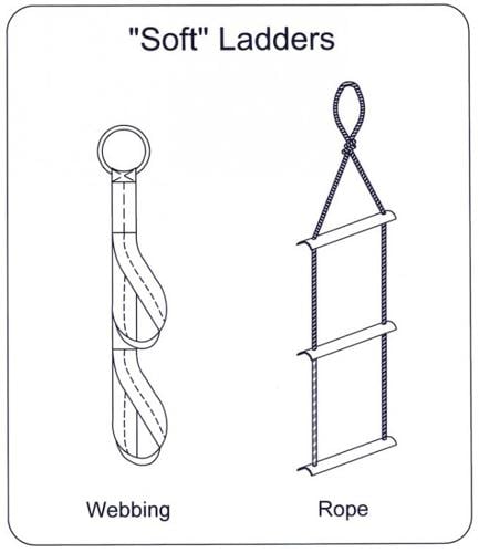
The closest would be the rope ladder on the right.
Design:
Anyway, DESIGNING:
(sorry if I cut the explanation short, but I feel like I put too much stuff in this project already)
Well, first:
Although I said "I wouldn't have to redesign much", I actually need to redesign something.
As you can imagine, not every bearing you can buy online or build at home will be able to withstand thousands of kilograms. And as such, I can't really trust on the structural integrity of everything I can build.
I mean, just watch the start of the Capstain Drive up there (at 1:52 more specifically), just 3kg weight at the tip of the arm was enough to bend the connection between the drive and the metal beam.
I just now remembered that I'm bad at 3D modelling...

Discussions
Become a Hackaday.io Member
Create an account to leave a comment. Already have an account? Log In.
I gave up on spring assist due to weight of the spring itself and complexity of mounting the darn thing, but it certainly is worthy of exploration.
Skyentific's orbital drive operates on the same principle as compound planetary gears. It's like having two gear sets with almost the same reduction ratio, and using the small difference between them to create an effectively much higher reduction ratio. The formula is "one minus the ratio of the ratios". The closer they are to exactly equal, the more reduction you get. For example if you have 11:50 on one set and 13:59 on the other, you get 1 - ((11/50) / (13/59)) = -0.00154 = -1:650 output ratio. Compound planetary can also have a sun gear as the input, which adds another small reduction factor and reduces the planet gear RPM which allows a bit higher torque. Or you can drive it via the carrier like the orbital drive.
As with all belt reducers, the trouble with orbital drive is how to tension the belts. Fixed center distance like the one in the video will never be able to carry the full rated torque, especially with so little engagement with the large pulleys. One potential solution is to use idlers to increase the wrap angle on the large pulleys and allow tensioning, but that adds to the already high inertia.
I'm using compound planetary gears for my humerus twist axis. Carrier-driven with two large sun gears and no ring gears, very similar to orbital drive just using gears instead of belts. Still higher inertia than I'd like, but the form factor is excellent.
P.S. You have great taste in anime :) Konosuba and Gabriel Dropout have some of the best comedy ever.
Are you sure? yes | no
why don't you research certain carbon fiber composites, they may help
Are you sure? yes | no
Actually I researched, the problem is that they are really expensive and peform quite poorly when the matter is impact resistance.
So even though a full carbon fiber structure would be able to withstand a lot of weight and tension, since the mech/exosuit would constantly be receiving impacts from falling on the ground or simply walking, the whole structure would eventually break sooner than other materials.
And, of course, it would be really expensive. :/
Are you sure? yes | no