21/01/2024, 08:22, Sunday.
I'm quite stoopid, I already said I gave up on the project, but I can't, for the life of me, just give up.
And besides, like I said on previous logs: looking for artificial muscles/soft actuators is my hobby now.
What I need to look for?
In any manner, using electric motors and combustion engines is a no-go for robotics, since a human speed exosuit/mech/robot would need megawatts of power to lift tons of weight, the only way I can make these viable is to reduce the consumption for at least 100 times.
And for that, I need to find a good actuator option that has a power-consumption below 1 watt in order to make this thing viable, more precisely, around Miliwatts of power. Which is 0.001 watts.
Electric motors are complex machines, but are very reliable and precise, I would love to "simply" make an electric motor that uses 0.3 watts (or less) per kilogram of force at 40m/s of speed... But it is not that simple.
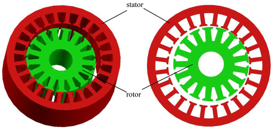
One way I could think of was to reduce the air gap between the stator and the rotor to micrometer or nanometer distances. After all, the smaller the distance between electromagnets, the stronger the electromagnetic field.
The issue is: the stronger the electromagnetic field, the stronger the eddy current, the reluctance and a myriad of different things.
Every type of electric motor is an ecosystem on its own, and in order to figure it out, I would need to understand the fundamentals of electric motors.
With that in mind, I found myself looking at a concept called "zero air gap permanent magnetic machines" with this paper: https://digital.wpi.edu/pdfviewer/9p2909417
One of the suggestions is using ferrofluids to "close" the gap, but as far as I could see it, it actually had some substantial effects, like almost doubling the torque of the electric motor.
But still nothing close to miliwatts...
It makes me question if the micro/nanometer gap would even make any difference at all...
Ah, by the way, the article talks about a company specialized in super tight tolerances and super dense brushless motors called "Thin Gap", which uses a slotless winding that I couldn't quite grasp how it is done.
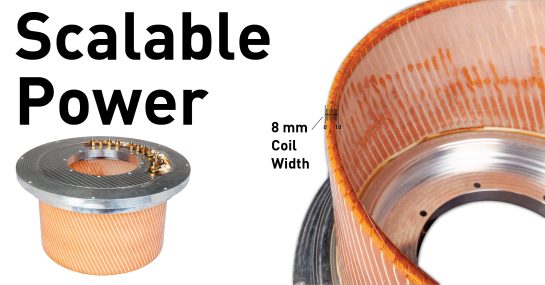
This one is said to have 100 kilowatts of power.
The paper I linked above kinda explained how these are done, but I don't think I quite grasped it yet.
In any manner, I can't find anything on the subject as much as I like, so I don't think I will have any luck trying to DIY my way into this type of exotic BLDC motor (and unfortunately, I would love to)...
I also searched for other articles:
- https://www.researchgate.net/publication/322650195_Airgap-less_Electric_Motors_with_External_Rotor
- https://www.mdpi.com/1996-1073/13/17/4286
- https://www.researchgate.net/publication/319035525_Airgap-less_electric_motor_A_solution_for_high-torque_low-speed_applications
If I didn't read it incorrectly, you can achieve up to 4 times more torque with the same amount of energy, which would reduce the power consumption from 3 megawatts to "just" 750 kilowatts, which is like, 1000 horsepower to lift 1 ton of weight.
Very interesting results, but nothing close to miliwatts...
They achieved that (if I'm not mistaken) by making the electric motor's rotor enccentric, so it physically touches the stator's teeth, like a radial piston engine, except with electromagnets instead.
So, if they literally physically touch and can only multiply the torque by 4 to 5 times, then this is probably a dead end.
The only reason the rotor strength doesn't increase even more is due to the fact that it is eccentric, only a small part of the rotor is touching. Only 2 teeths out of 17 teeths are in direct contact with the stator, so I could imagine a maximum increase of 8.5 in torque if full contact was possible. And it would probably be possible by stacking the eccentric just like radial engines did:
Assuming a gross approximation of simply taking 3000 Nm (to lift 1 ton at 30cm distance) and divide it by 4 and then further by 8.5 it would reduce the power consumption to 2300 watts from 78,000. Resulting in a total of 92,400 watts, or 123 horsepower for a full mech/exosuit.
This is a reduction of 32 times, not 100, but it seems viable to me.
Well, I do wonder how long these eccentric direct contact electirc motors would last, even with proper lubrication...
One could shape them like gears... Which would be interesting...
Hum... This makes me remember of this type of pump:
Maybe an hybrid of both could be made for a hydraulic pump?
Oh yeah, I think this is relevant, but I don't know how to explain in a quick way. But basically:
The directly-tounching electromagnetic teeth of the electric motor work more or less the same way the holding electromagnets.

These use very low energy, around 14 watts to hold 100 kilograms (0.14 watts per kg), and the direct-contact electric motor would do the same. But like I said: it uses this energy to hold such weight, not to move it.
An electric motor with such design would need to take into consideration the distance between the teeth of the gear I showed before, since some teeth would need to be electromagnetically attracted to rotate.
A mere distance of 1mm distance is enough to reduce the electromagnetic field for for more than half of its power, so the teeth's clearance must be very tight and require a very well thought design and control in order to diminish the waste of energy in other distances. Which could make this very expensive to make this custom motor from scratch...
Yes, I did say that electric motors are expensive, copper is also expensive and so on. But honestly, electric motors are way more understood and widely used than other options. It is way more practical to tell someone to make an electric motor with better precision than to go into uncharted territory and face thousands of different issues that no one has an answer for.
But an electric motor? Ask a professional why the machine is acting in a certain way and they will have an answer.
In either way, I will """just""" need 1 electric motor per mech/suit in order to drive a hydraulic pump.
I will try to study and test every option before I finally come to a conclusion.
Steam-driven Actuators:
The first thing that comes to mind (besides electric motors) is the steam powered actuators.
There are a couple of ways of achieving this, but first things first:
- 1 liter of water can be turned in 1600 liters of steam.
- Since steam is compressible, these 1600 liters must divided by the amount of pressure that will be used.
- The faster you need to heat the water the more energy you need.
In 1 Hour takes around 750 watts.
In 1 Minute takes around 43,000 watts. - The bigger the pressure, the higher the temperature to turn water into steam. Around 5 bars, the amount is negligeable.
- Electric to thermal conversion is 99%, the thermic energy used to transform water into steam is also 99% efficient.
- Using steam alone to actuate things has maximum efficiency of 30% to 40%.
- Steam powered actuators can lift at least 1000 times its own weight.
With this alone, steam doesn't seem much attractive, but you need to remember that water isn't the only thing that can be turned into steam, neither that using a simple resistor is the only way of heating it up.
Liquids like ethanol, ether and chloroform have boiling points around 30ºC and 60ºC. Which can be used, chloroform is the only one not flammable, buuuuut... It is toxic to humans.
The only liquid that the fricking half-useless BingGPT suggested that isn't flammable nor toxic is Novec 649, a fire extinguisher and coolant that has a boiling point of 49ºC. So it would consume half of the wattage's water.
In any manner, I found this article:
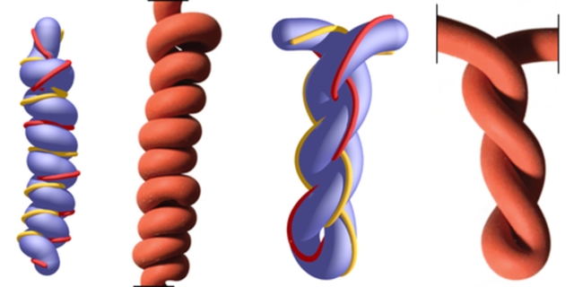
"Preparation of Linear Actuators Based on Polyvinyl Alcohol Hydrogels Activated by AC Voltage"
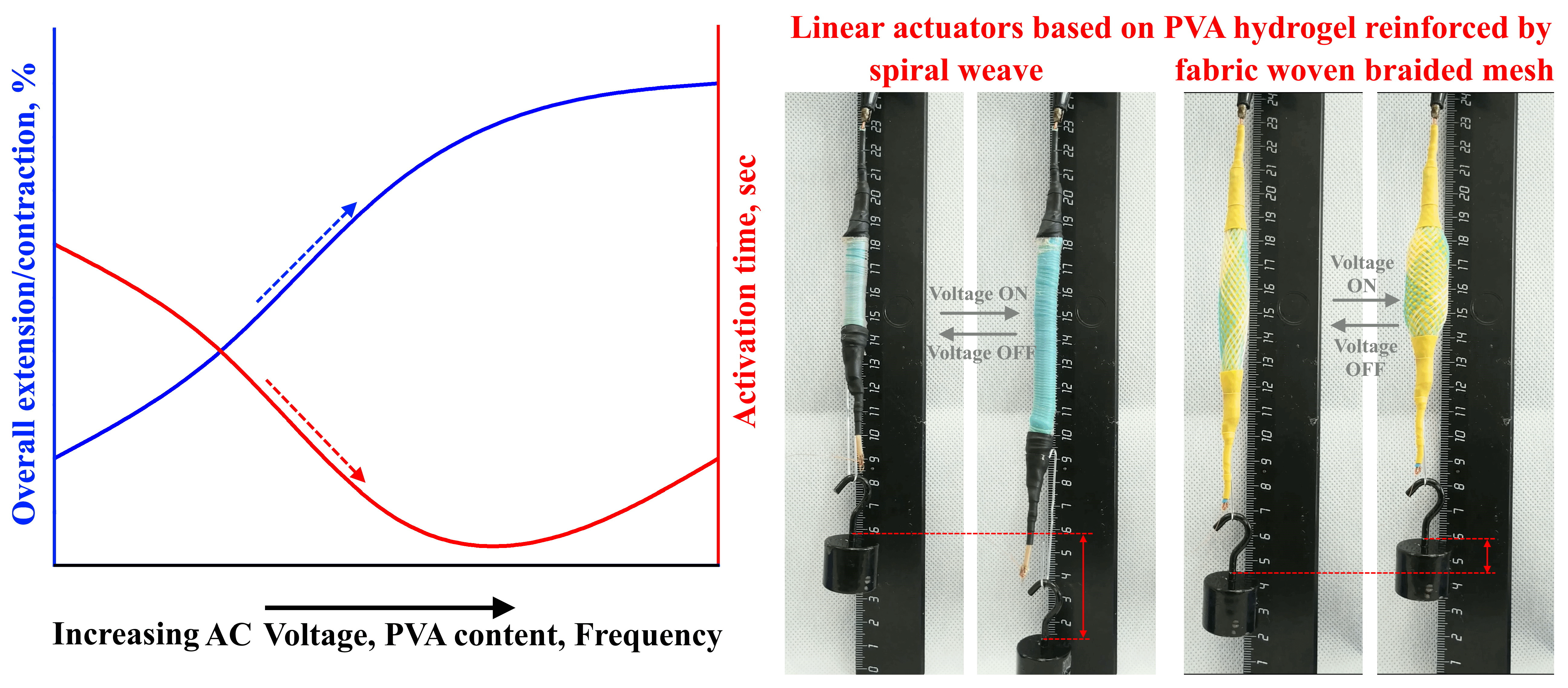
Source: https://www.mdpi.com/2073-4360/15/12/2739#
It uses PVA hydrogel with borax (slightly conductive) and distilled water, however, the current used to heat it isn't DC, it is AC at 220V and 500 Hz with an efficiency in the 0.8%'s.
The interesting part though, is that it uses only 0.04 watts of power, around 40 miliwatts and it takes around 1 to 2 seconds for full contraction.
And besides, I don't even know if it would be better to have a central "steam converter" using hydrogel fibers (as in the article) or resistive sponges to make steam and use a Steam Injector or use the artificial muscles to rotate a water pump.
Let me explain:
Steam injectors are water pumps (or steam pumps/jet pumps) with 95% of efficiency in pumping, while the artificial muscle driven pump (imagine a piston engine, but replace the pistons with muscles) would have around 40% of efficiency (and yes, it would still use miliwatts of power even while using more than twice the power).
The steam injector pump rubs me the wrong way because it is fricking steam, it is basically a bomb. Yes, I could limit it to 5 bars (around two times a pressure cooker takes), but even so, it would still be dangerous in some level, specially with the amount of steam required.
... Maybe I'm being too overly cautious with this, fire extinguisher tanks are meant for 2 MPa, around four times more pressure than I intend on using.
I could use discarded ones for the boiler.
BingGPT said I would need around 10 bar of pressure in order to pump a fluid to 5 bar of pressure in a Steam Injector/Jet Pump system.
I know that it sounds strange to use an artificial muscle to drive a pump, but hydraulics have a lot of advantages, for example:
I don't know how to make a compliant hydraulic actuator, but hot dang, is this fast (and strong, in the description it says it has a force of 10,000 Newtons, or 1 ton).
Accordingly to certain articles, they use a miniature hydraulic accumulator for passive compliance. The only issue I have with it is that they change the stiffness of the compliance by changing the pressure in the accumulator's bag/bladder. Not a big problem of anything like that, I just don't like the extra amount of complexity.
One could simply add a spring accumulator and adjust the stiffness by compressing it more or less, you know, by just rotating a nut or something among the lines.
This paper suggests using magnetic shape memory alloy, but one could also use magnetorheological/electrorheological fluids that changes viscosity with magnetic/electrical forces being applied to it.
This could mean that:
- Water could be turned into steam with the same wattage using the same hydrogel borax method.
- The use of a highly porous heating element could highly improve the water to steam conversion.
But again, the only way to be certain is to test things out.
But again², I'm broke.
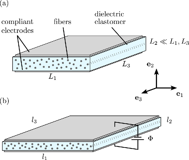
Dielectric Elastomer Actuators:
Well, if you read the previous project log, you know the drill.
- Dielectric Elastomer Actuators have efficiencies above 90%.
- They can be 3D printed and/or 2D printed.
- They have multiple types of stacks that highly impact its contraction.
- They need really high voltage and high low amperages, around 5000 Volts and 0.00025 amps.
- They work best with really thin layers and really thin electrodes, which can be hard to make.
- Most dielectric elastomers actuators can lift around 50 to 100 times its own weight, which is a problem, but it can be a result of its implementation. The use of fibers can solve such issue.
- Bubbles and material quality can heavily influence the efficiency and performance of the actuator.
- Not many examples out there, this can mean lower endurance.

Source: https://www.pnas.org/doi/full/10.1073/pnas.1815053116
I thought on using a 3D printer with a syringe needle as the extruder in order to make a continuous 3D printed Dielectric Elastomer Actuator stacked in the same manner as in the image.
However, like I said, the thickness of the layers is imperative, and I really don't think I can achieve such insane precision with a DIY 3D printer.
One of the possible methods is using Airbrushers and mixing silicone rubber with alcohol (or acrylic with acetone), which makes the silicone rubber less viscous and allowing for an even thinner layer.
Heating the bed would also allow for faster curing time.
But I would need, like, one of those belt 3D printers.

One of my ideas for this actuator was to use microfibers by extruding conductive polymer through syringes and making micro-wires or even nanowires. The wires would be the electrodes and the dielectric layer would be over them, the positive side would be covered in Polyvinyl Alcohol and the negative side covered in Polyvinyl Acetate.
This way one could use water to dissolve the dielectric layer of the positive electrodes for power connection while using acetone to dissolve the Polyvinyl Acetate covered negative electrodes.
Well, the idea is that both fibers would attract each other and twist in someway, but I have absolutely no idea if it would happen.
(something like this)
In any case, I'm at a loss on how I should use the dielectric elastomers.
Should I use them directly into the suit? Should I use them in an piston engine configuration where the pistons are pulled by the artificial muscles?
I feel like the motor thingie would be easier to produce, no? I would need to make the same exact actuator and glue them together in a radial configuration.
It would spin at a predictable speed, with a known force and a known stroke. Either to drive a hydraulic pump or an electric motor (I like the electric transmission idea, but you know, it is very expensive).
While the direct attachment would need to be considered, the fibers need to be glued to the bones (that could unglue at any moment) and so on.
I do like the idea of direct connection, but the constant exposure to outside elements (even with fabric layers of protection) could damage the already fragile fibers.
The hydraulic pulling actuators would be made of recycled, more resistant materials like PVC, Polyethylene and the likes of it.
Another argument that could be used for the use of artificial muscle driven pump (and valves) is the fact that you can't make precise movements with the Dielectric Elastomer Actuators (DEA), like the Pneumatic Artificial Muscles, it is either on or off precisely because of the way it works. If you apply less voltage in order to parcially contract the DEA muscles, you would also use the parcial strength.
The strength applied by the DEA is equal to its electrical force, so you can't position it precisely, unlikely electric motors and hydraulic actuators which can tweak with its rpm and torque at will.
The only I could think of circumventing this (besides individually activating fibers, which is too labour intensive) is by rapidly turning it on and off before it can actually fully contract.
But this would need an unknown amount of hertz and a encoder on the axis of the artificial skeleton (either of an exoskeleton or mech) for full position control.
But again, the only way to be certain is to test things out.
But again², I'm broke.
Dielectric Pump:
Speaking of dielectrics, let's talk about dielectric pumps.
- They also use high voltage low amperage just like dielectric elastomers, requiring milia
- They can also be 3D printed without the precise requirements of Dielectric Elastomers Actuators.
- I couldn't find the efficiency of such pump, but it doesn't matter.
- Its performance depends on the number of electrodes, length of the fiber pump and dielectric properties of the material.
- The fiber pump in the article uses an specific chemical liquid that forces passivation of the copper wires after 3-5 days of continuous use. Passivation occurs when a high voltage low amperage current passes through a metal material, which forces an oxide layer on its surface in the presence of certain materials.

Source: https://www.science.org/stoken/author-tokens/ST-1105/full
The paper of this fiber pump uses an specific dielectric liquid that costs thousands of dollars per liter, however, one could replace it with other liquids, such as oils and deionized water.
It is meant for microfluidics, meaning that using it for hydraulics that needs dozens of liters per minute and several atmospheres of pressure will require way more voltage.
Another concern I have is Passivation.
Although the paper uses a very specific liquid, the passivation of copper (or metals in general) can occur at myriad of different conditions, even by exposing it to air.
Passivation generates a oxide layer on the material, in other applications it is good for corrosion protection, but in this case, it can literally make a insulation layer between the metal connections of the conductive materials.
What a pain would be if every X amount of time the thing simply stops working because an oxide layer was created in every possible connection, essentially killing the electronics?
The only solution I can think of is using conductive polymers (like silicone rubber mixed with carbon powder) in the place of copper on the system that converts the current to very high voltage very low current.
And the only system that I can think of is a transformer, and I'm not very sure about it either.
I was thinking of making a fiber pump for every individual actuator, which seemed like a good idea, but I'm wondering if it really is.
Each fiber pump has to be at least 5 meters long and have multiple tubes, I thought on wrapping them around each actuator, but taking into consideration the absurd amount of actuators required and the small space they will be fitted in, the pumps would probably be rubbing on each other during activities, and thus, slowly being degraded.
A central fiber pump would be a better option, I suppose, but I find hard to imagine would I would fit a 5 meter long fiber pump with a thickness of a human body inside a mech.
But again, the only way to be certain is to test things out.
But again², I'm broke.
Testing things out:
I'm going to try and buy the equipment for this endeavor during next months, but I wish I could already test everything.
I bought the adjustable power source for around 40 dollars, which is around 200 reais + import taxes.

Here is the pic:
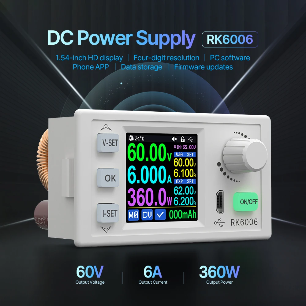
The first annoyance is that the high voltage converter only works with 400 kilovolts and above, I just need 3 kilovolts, specifically because of dielectric breakdown. The materials that I have available aren't the best, neither the most expensive, unlike the ones used on the dielectric elastomer actuators papers.

There are adjustable kilovolt power sources, but they cost thousands of brazilian bucks.
I will, unfortunately, be forced to make my own.
On top of that, I will be forced to use a faraday cage, because once I saw a guy make a homemade ionocraft while using these High Voltage generators and all of the electronics on his house simply fried because it was liek a continuous EMP.
I'm 2 minutes in and I already want to give up.
Can someone do it for me, please? y-y

Discussions
Become a Hackaday.io Member
Create an account to leave a comment. Already have an account? Log In.
lol been there buddy, mercosur hates international purchases it seems, it was the same in Uruguay when i used to live there.
I recommend looking into old CRTs for high voltage equipment, or Plasma TVs (those used to be popular in my country)
But even so, I think pneumatic systems might be cheaper to get into, even if the solenoids and valves might be a bit tedious to find for a good price, oh and pneumatic muscles are super simple and cheap to make. Painter's compressors are a good way to get into pneumatics.
Are you sure? yes | no