Thursday, 06/07/2023, 12:40.
(I wrote this project log before copy-pasting it here)
Anyway, back to DIY electric motors:
I can't simply use two 10:1 reduction ratios (which would give 100:1 in total) simply because if I want to reach 30 rpm with a 100:1 reduction ratio it would take too long, and besides, I think it is for the best if I actually follow the experts advise on it.
And thus, I think it is for the best if stay with the 4500 to 9000 watts (6 and 12 hp) wattage for the actuators, not because of the wattage on itself, but because of the structural integrity. The 9000 watts actuator will rotate a 10cm diameter (5cm radius) hoist/winch, and thus, a 10 cm diameter HDPE reinforced beam would probably be able to withstand such loads.
Of course, the load will be equally divided between 6 actuators, and thus, they would be operating at safe parameters.
In any way, I believe I incorrectly wrote the values. For example, if I add a 5cm radius distance and a force of 30,000 newtons (3000 tons to lift 1 ton at the said distance), I would need 1500 newton meters, and thus, with 30 rpm (15 cm per second of linear speed), it would give 4713 watts of power (6.32 hp), not 9kw.
I wonder were I took that 9kw from... hum... I think it was because I thought I would need to double the torque or the rpm...
Anyway, since I can only use a 10:1 reduction, and since I would divide the entire load between 6, or at worse, 3 (in the case of hexapod rotation), I would need electric motors with 50 newton meters of torque.
Meaning that I would need around 25 of those brushless motors I were intending on using. That Eagle power one.
So, instead I think I will try to find a 3D model or a motor that can be bought with 50 Nm of torque.
... And it is harder than it looks like... I ran through a bunch of 10-15kw brushless motors that can't even make through 5 newton meters...
------------------------------------------------------------------------------
... Dunno if I already posted this, but I think it would be interesting to use the REB-90, a 80kw brushless motor with 300 newton meters of torque.
Obviously, I won't make something with actual 300 newton meters of torque, I will downside it a little bit because it would need around 100 amps, which is quite dangerous.
Besides, the motor has 13 to 20cm of height and 27cm of diameter, it is a chonky boy.
Edit¹:
Do NOT take my advice, first consult a professional.
I was looking here after a look at Dekutree64 advice and aparently, our skin has a resistance of 100kOhms, meaning that a 100 amperage current with as little as 1 volts would only pass 10 miliamps (0.01 amps) through the insides of our body.
So every electrical discharge has to first pass through the resistance of your skin (that diminishes significantly once you're wet), and then the resulting current may have consequences on your body.
However, how much the amperage/voltage will damage your body is like defining how lethal a bread knife will be lethal to you.
Depending were (like your heart) and for how long, the electrical discharge can be fatal.
Even 7 miliamps (0,007 amps) passing through your heart for 3 seconds would be enough to stop it.
But, as said before, it would need to surpass the resistance of your skin, then reach specifically for your heart.
___________________________________________________________________
However, while I was comparing the 3D model to the photos and engineering illustrations that the own company showed and the link I just posted of GrabCAD, I noticed that the 3D model is just a mocap (it is on the description, but I didn't read, lol). The stator in the real thing has 45 teeth if I'm not mistaken.
I tried to take the picture put it on a image editting software (krita, which is free and open-source) and simply took a section of 3 magnets (that you can clearly see) and then copy past these "pizza slices" until they made a full circle, and I counted around 60 magnets on the rotor.
I asked to chatGPT the relation between the number of stator teeths and the number of magnets and it said that such brushless motor should have around 31 magnets.
Well, I tested align the 3D model magnets and the magnets in the pic, and it seems that 60 is the correct number.
------------------------------------------------------------------------------
I Couldn't find more pics of the REB-90, but I did find pictures of the REB-60, which is actually 60kw in power, has 250 Nm of torque and 4000 RPM.
It is thinner and the images show every part of it, which is a bonus.
On it I counted around 45 stator teeth and 60 magnets and based on the wattage, it would need around 75 amps (75x800 = 60,000 watts).
This would mean that the only difference between the different types of REB motors is the thickness of the magnets and stators (on top of the winding thickness and so on).
------------------------------------------------------------------------------
In the previous project log I suggested using electroplating or sputtering on cut into shape aluminium foils and then stack it as a stator, but I'm starting to rethink it, more or less.
Sputtering is quite hard and expensive, although it would give me a lot of options for both fuel cells and electric motors... But... After looking more into it, I really can't make such system in a homemade configuration in the cheap.
You can't really use the "cheap" 400 reais (83 dollars) vacuum pumps you find online, you need a super low pressure vacuum pumps that costs around 1000 reais (200 dollars) or even more.
And Sputtering services cost around 70 dollars per hour of service, and meaningful coatings of metals take around 20 to 30 minutes.
I found this video here, but I don't know if I would be able to make it (due to skill issues).
He says he uses "microns" (aka microns of mercury), which 89 micros is around 0.089 torr, but high vacuum starts at 0.001 torr, not the ideal condition for properly made Sputterings, but hey, it is cheap.
Welp, maybe one could make this oil pump for high vacuum with a negative casting piece, and you could make it with tin, zinc, lead or anything that doesn't melt at around 50 to 100ºC.
Maybe the guy (or me) could make it at simple plastic. Such teflon. :|
I asked chat gpt for metals that can be melt in a frying pan:
Tin (Sn): Melting point of 231.93°C (449.47°F)
Lead (Pb): Melting point of 327.5°C (621.5°F)
Zinc (Zn): Melting point of 419.53°C (787.15°F)
Bismuth (Bi): Melting point of 271.4°C (520.5°F)
Cadmium (Cd): Melting point of 321.07°C (609.93°F)
Indium (In): Melting point of 156.6°C (313.9°F)
More information:
"Diffusion pumps, on the other hand, rely on the principle of vapor jet diffusion to achieve high vacuum levels. They typically use a low-vapor-pressure oil as the working fluid, but the oil does not boil as part of the pump's operation. Instead, the oil is heated to a temperature high enough to generate a vapor jet that entrains and pumps out gas molecules from the chamber."
"Oil diffusion pumps can operate well with wall temperatures of 86°F (30°C), whereas the walls of mercury diffusion pumps must be cooled to 59°F (15°C)."
Source.
For even higher vacuum: "10-5 to 10-6 Torr = 180-190 °C".
Source.
So I would need a fridge air compressor to be used as a vacuum pump (yes, vacuum pumps are literally compressors used on the reverse) and then use the diffusion pump.
------------------------------------------------------------------------------
So, unfortunately, or fortunately, I will be using elctroplating nickel, iron and I will try to attempt on using silicon metal to do it aswell.
I will try to electroplate graphite/graphene powder by using the following setup:
Negative and positive electrodes made of the same material and put a low speed mixer in the middle, the electropalting will innevitably hit and/or use the partially conductive graphite/graphene and coat/cover then in a layer of the desired metal.
I will then use the final powder to make the soft magnetic composite material for the stators of the electric motor and/or use the resulting powder as the catalyst of the alkaline hydrogen fuel cell.
I think I would try this water blade:
It would also take days to usefully coat all the kilograms necessary to make it work, but at least it would be dirty cheap.
In fact, so cheap that I will try to finally make it for real this time.
(I was going to try it for this log, but I forgot to buy it, and got too focused on this electric motor, so... It is for the next project log I guess)
Although I need to make a correction: I believe I can't really use pure iron with the vinegar salt solution, I would need to use sulfuric acid for that, which is... Dangerous.
------------------------------------------------------------------------------
I was asking around and I heard a very good piece of advice:
"Electroplating electrolytes use very specific formulations. Yes you can deposit a little something with a poorly formulated solution, but to electroform you should use a proper formulation. I know several people who have spent their entire working life specializing plating just one metal. Tin or copper or gold…. It can become quite complex and details matter. Look around, you can purchase ready made electrolytes or find the recipe and make it yourself, but finding the correct components will take commitment."
Although it is a good advice, the electrolyte solutions costs around 400 reais (81 dollars).
------------------------------------------------------------------------------
Anyway, AWG for the copper wire.
If you don't know what AWG is, it is basically the standard of diameter and electrical resistance of a certain type of wire. In this case, enameled Copper Wire.
The bigger the diameter, the bigger the current or voltage it can pass through it without melting.
However, for some reason, every list that I come by has a different value for every AWG. Some don't even have amount of current on the AWG for some reason.
On wikipedia, a 10 AWG has a maximum 15.8 amps of limit, while in other sheets, the maximum amperage for power transmission is 15, while maximum amperage for chassis wiring is 55.
https://pt.wikipedia.org/wiki/Escala_americana_de_bitolas_de_fios
The other sheet:
https://www.powerstream.com/Wire_Size.htm
While in this one, it says it has 35 of maximum amperage:
https://learnmetrics.com/wire-gauge-chart-amp-wire-sizes/
Some sellers may or may not tell you the maximum amperage of their copper wire, but they will definitely tell you the AWG. Thus the need for such sheets.
In any case, not having the propper AWG for your application is not the end of the world, even properly made high amperage cables/wire often are made with multiple wires of lesser amperage, thus distributing their amperage through all the wires (or so I thin).
(I asked some sellers on brazilian websites and they said it is 30 amps for 7-8 AWG)
------------------------------------------------------------------------------
The other problem that I need to solve is figuring out how many turns of copper wire each stator on a REB-60 has, this is as equally relevant as any other matter of the subject, because if you put too many turns, the voltage can drop and be converted to heat, or you may have a too little turns and have lower eletromagnetic strength.
Although, if I had an actual 3D model with all the parts of this electric motor, I could say it is a copy, but since I will be going in blind, I believe it is already a completly different electric motor.
So let's change the name, instead of REB-60, let's call it something like PEG-69 ( ͡° ͜ʖ ͡°) hehe.
------------------------------------------------------------------------------
Anyway, 3D modelling this dang thing:

I changed a lot of proportions for the sake of toughness, In my little brain, it all seemed too thin and fragile, but now I'm starting to regret my decisions (as always), because a little change in size could strongly affect its efficiency (I think).

Luckly, I started with the electric motor normal proportions and changed it afterwards, so I don't need to redo everything...
Bruh, I just did this right now and I feel tired and lazy as heck...
Also, I was thinking here: this is a BLDC motor meant for aviation, right? So the cooling system is entirely based on the air pushed by its props, right?
So, I think I would need to make some modifications to allow for a deionized water cooling, like putting everything in a closed space, using potting to waterproof everything and so on.
I would need to do potting anyway, since I would need to protect the motor against mud, water and stuff like that, so I guess it shouldn't be that bigger of a problem.
And with that, deionized water is optional, but it is an extra layer of safety (electronics don't fry when exposed to deionized water or mineral oil, but mineral oil for electronic cooling is expensive as frick here where I live)
Potting, for those who don't know:
... The question is:
How the heck I do that? I'm bad at 3D modelling y-y
Luckly there are a ton of tutorials on how to do it, so I don't really need to make it from scratch.
Also, I took a look at actual brushless motors that are watercooled and/or waterproof.
The last one uses a thermal paste on the coils for efficient heat transfer, I guess one could mix thermal paste with plastic/resin in order to achieve an efficient thermal transfer.

So, I made this 3D model like this for a couple of reasons:
Initially I wanted to make everything connect to a central fixed rod, so it would be easier to align everything. But after a while I got even more confused how I would fix a round/square rod supposed to lift tons of weight in the structure of a future mech.
So I deviated from it and came back to the original design of the REB-60, where the rotor is connected to a giant bearing in one side and a smaller bearing on the other side where the shaft is connected.
So I did a bigger ring/tube on the inside and a smaller ring/tube on both sides, so, supposedly you were going to cut it on one side and keep the other the same and also, supposedly², put the electronics on the space in between.
But now that I stopped to thing about it, I don't feel like it is a good idea at all... After all, how you would put that on a laser cutter? You would be forced to use a big ass 3D print that may or may not have a lot of defects (and probably won't even fit in your 3D printer bed).
So, right now I will need to remake everything with the laser cutting in mind.
I was thinking here: how the heck I will attach the magnets on the inner part of the rotor? Even milimeters of distance can decrease the magnet force substantially. I was thinking on adding fibers (glass or carbon) and felt made out of the same fibers in front of the magnets (or the mockup of the magnet)so when everything dries out, the magnets are as close as possible to the electromagnets.
As consequence, the rotor will have to be thicc as heck.

I hope I can explain this in a comprehensive manner...
Basically, What I've done was adding a 5cm diameter rod at the center, a concentric 10cm diameter rod then the stator, then the magnet and then the rotor.
The idea is that you can take these rods and concentric rods and chip off the imperfections and arrange them on your choosing for the mold.
The concentric rod could be the space to add the other side of the rotor, while the inner rod could be the thinner side of the rotor, just like in the REB-60.
However, you could make a bigger concentric rod or anything like that and make a perfurated stator with some holes for screws or nuts with the size of your choosing. Just like in the example on the left, although the holes are place in a quite weird place.
Then, on top of all of that, you could place homemade lids on each side of the rotor and glue and/or screw everything together.
Although, unfortunately, you wouldn't be printing/molding everything in one go, except for the stators, I do think it would be possible to make everything in a homemade lathe of some kind.
Since the material which one would use for the laser cutting could be styrofoam or other kinds of plastic, you could take a few liberties on how to build your thing out of this model.
I added the blender 3D model on the files of this project by the way.
Edit¹:
I also added the modified 3D models on the blender file of the Eagle Motor and the U8 Lite motor.
_____________________________________________________________________
OFF-topic:
For some reason, continuum robots (aka tentacle robots) are drawing my fascination again for some reason. I don't really understand why my brain goes "continuum robots better", but I simply think these would be the excellent robots... Except for heavy cargo.
Right now continuum robots are not known for precision and strength, but for human interaction (the normal one, not... you know) because you can't really be killed by a balloon.
But it came to my mind that maybe I could maybe stack dozens or hundreds of continuum robots together in order to make a robot.
Of course, artificial muscles aren't really efficient with todays technology (to my knowledge), but electric motors are, and I could equally stack continuum robots just the way someone would stack artificial muscles in a body.
On top of that, it could still be safer to work around humans, since the hundreds of "cords" would be equally distributing all the loads, it would like if a bunch of stuff were dropped on top of someone.
... Not a pleasant experience, but better than a giant solid single stuff falling on top of you.
Although you would still face the same problem of lack of efficiency just like conventional humanoid bodies: the top actuator will be sustaining the weight of the bottom actuator instead of all of them working together for ultimate efficiency. Unlike the stewart platform limbs I was planning on using for the mech/exosuit.
... Or maybe not. I just remembered that some continuum robots/tentacle/robots are actually 3 or 6 tendons directly connected to the entire structure until its tip.

I could connect the tendons just like a giant stewart platform; and on top of that, I do think it would be possible to add the movement of the feet, hands and its fingers to the stewart platform spine as well in order to increase its movement range, equally distributing the loads.
... Although the idea of hundreds of tentacles is interesting, the idea of building hundreds of tentacles is not so much...
Imagine making 100 DIY brushless motors... ugh...
It would still be better to just make 1 tentacle per limb...
However, a good side for this is simplicity. I don't need bearings, universal joints and things like that, "just" a spine of a tentacle and a rope attached to a motor with reduction gear or not. But I do believe I would need some kind of "spacer" between each "bone" of the "spine", I think it would be interesting to use low pressure pneumatic cushions, I could even use these to enlogate or change the shape of the limb entirely based on which balloons/cushions I fill. Which would also relief the amount of energy required to run the torso acutuators, reducing the energy cost even more (although I think it would be the best to not have a torso in this continuum mech).
Plus, I could make every spine vertebrate the same thing or different gradiants of thickness/length/diameter, which would make the body even easier to build in a DIY setup.
... I hope I'm not jumping to conclusions, but I think this is sounding better and better.
------------------------------------------------------------------------------
Also... I feel like I already talked about this idea before... But I don't quite remember if I actually wrote about it here...
Well, I couldn't find any kind of concept art that shows exactly what I'm thinking, but this little drawing that I found may be useful to explain:
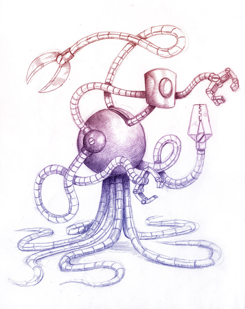
(source of the art: https://www.deviantart.com/jcoon/art/Tentacle-Robot-441291077)
Just imagine these tentacles he is sustaining himself onto actually two legs or arms, but shorter.
------------------------------------------------------------------------------
Also, i was trying to find a mechanism that can both push and pull in order to help with the continuum robot limbs, but I can't find anywhere such thing... Except on autoloader tanks.
In some soviet era tanks there is a little arm that pushes the amunition into the tank cannon, but these retract in a spiral inside a compartment.
I'm still trying to figure out how these work and what is their limitations, but I don't really know what is even the name of such mechanism.
(on the left shows it working)
The other mechanism that is similar to that is the zipper linear actuator, and I can find even less information on the subject...
(this last one shows how it can be bendy, but it looks like an unwanted feature rather than the objective)
Funny how I started this project because of this actuator, and I'm back at it again...
I found these two types, I wonder if it is the same thing...
In either way, I think it would be better to use such mechanism in the rigid body type and/or the continuum body type, it seems better than using hoist/winch mechanisms...
------------------------------------------------------------------------------
Welp, while thinking a little bit harder about the whole zip-chain mechanism, I was wondering if it would really work as a pushing mechanism.
You see, I was wondering it really would be possible to push tons of weight with such fragile-looking mechanism, if there is an engineering limit that I can't calculate due to my lack of knowledge and instead of actually pushing stuff, the zip-chain would just bulge/collapse on itself or inside the tube-channel in which the zip-chain would be travelling inside.
Not to mention that it would probably be a hell of a job to make a zip-chain actuator since I was already having a hell of a time trying to make a conventional sprocket.
In any case, I was wondering in a way of achieving that with the pulling mechanism alone of these conventional spinal continuum robots.
The idea is basically: imagine a single spinal tentacle robot with a pulling string in opposite sides, denpending on which side you pull, you will make it coil in the direction in which the mechanism is being pulled.
Now, imagine two parallel tentacles that work the same way, but these are glued together or simply glued only at the tip, if both pull the right string, the entire thing will move to the right.
But, if you pull these two strings with different forces, you could make the entire tentacle move upwards and coil itself at same time (I think).
The same way, if you were to pull the two right strings at same time, but a single one left string, it would (probably) move the entire tentacle arm backwards while coiling the thing, like you were to contract your biceps and move the arm backwards.

(i've drawn the supposed stewart platform design with perfect hexagons because I forgor about this detail, but just imagine it is the face of stewart platforms)
Now imagine this, but instead you are doing the same "string-play" with 6 tentacles at same time, and each tentacle is a stewart-platform tentacle.
It would allow for an enormous variety of movements while distributing the loads throghout all the tentacle.
(I think).
Actually... I'm really starting to doubt if this is going to actually work >.>
I would need to find a way of making a simulation like that, and on top of that, I would need to find a way of controlling the limbs somehow... >.>
------------------------------------------------------------------------------
Also, I just rememebered what I talked about in project log 16, if I can make a mech safe to be around, I can make an exoskeleton even safer to use...
Discussions
Become a Hackaday.io Member
Create an account to leave a comment. Already have an account? Log In.
If you haven't seen this, it is very useful https://www.bavaria-direct.co.za/scheme/calculator/
Type in the number of stator teeth and rotor magnets and it will show you how to wind the coils. 45N60P looks exceptionally easy, with them all wound in the same direction, and each phase you just wind every third tooth.
Don't worry too much about the wire gauge. What really matters is the total mass of copper you can fit into the slots, which is about the same either way. Thinner wire/more turns will use more volts and less amps. Thicker wire (or many parallel strands) with fewer turns will use less volts and more amps. The waste heat for a given torque output is the same either way (and heat is what limits your usable torque). Low amps and high resistance, or high amps and low resistance. So the wire gauge and number of turns is really just a way to match the motor to your desired power supply voltage. And since the motor controller uses PWM to effectively change the voltage applied to the motor, there's a wide range that will work.
Low voltage/high current is safer. It's true that current is ultimately what kills you, but it's the voltage that causes current to flow in your body. Low voltage won't do much to a human because our skin is high resistance, but can still cause very high current to flow in a fat copper wire. The main advantage of higher voltage is that you can use thinner wires from the battery to controllers and controllers to motors (less cost and weight, and easier to work with).
Are you sure? yes | no
Thanks for the help :)
It is always nice to have people to help you out. xD
Are you sure? yes | no