Sunday, 13/08/2023, 10:55.
I can't believe I'm saying this, but I think I will go back to the reversibly actuated artificial muscles.
Yes, I know, I know, I just wasted so much time taking each single approach for their efficiency and now I'm throwing everything away (again) for reasons (sometimes I think I just keep remaking decisions every time I face a problem because deep inside I don't want to get my butt off the chair and to this stupid thing [not to mention how ridiculous it is that every time I say "I will just make both options" and end up making no option at all {and every time it happens I have some kind of existential crisis for some reason}]).
Reversibly actuated hydraulic artificial muscles and hydraulic McKibben artificial muscles are only 60% efficient compared to hydraulic cylinders, which are 95% efficient.
... But the high efficiency come with a cost (not only monetary cost), they are heavy, bulky, difficult to produce (in a DIY way) and require high precision (for a DIY setup).
Reversibly actuated hydraulic muscles on the other hand are just a tube of elastic material wrapped in fishing line. And still get 60% of efficiency.
I calculated that I would need 3 kilometers of latex tubes, which would weight 15kg in total, while the hydraulic cylinders on total would weight around 100kg to 300kg. Which would mean that the mech/exosuit would waste more energy carrying this extra weight around, reducing the efficiency of the system.
So even high efficiency actuators make the overrall system more inneficient, while the inneficient actuators make the system more efficient.
Kinda ironic...
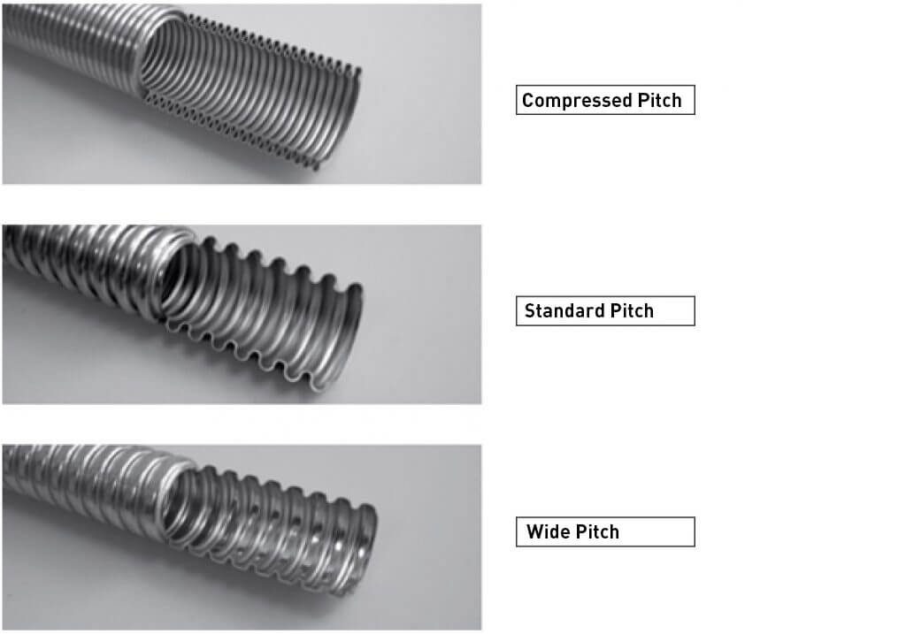
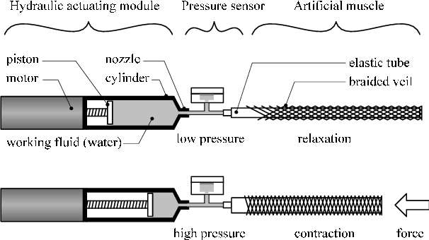
Just to recapitulate what I'm talking about:
By the way, since this kind of artificial muscle has 300% of stroke (3 times its initial length), then this means that it can be used just like the telescopic linear actuators. Which would be a positive... If I actually 3D modelled the exoskeleton/mech in the first place instead of just writting about it for hundreds of pages. :|
In any way, this means that now I need fo find a way of making a lot of tension springs and/or elastic rubber bands.
The reversibly actuated hydraulic artificial muscle (I will start calling this just "RAHAM" actuators) works by increasing the pressure with a fluid (air or hydraulic), but making the elastic element elongate, once the pressure is released, the spring element returns to its original shape.
I'm saying "spring element" because you don't really need to use only a tube of elastic rubber/latex, you could use a literal cylinder and calculate the force applied to the cylinder head/base of the thing.
One of the reasons that I gave up on the idea too early was the fact that it needs to keep all the actuators constantly under tension/pressure, which can diminish the life span of the RAHAM actuators.
However, I believe that this problem in specific could be solved by simply enlogating the elastic element bellow its capacity, just like you wouldn't work with an engine on its maximum load for much longer.
However, the only problem with this approach is that I need to find a way of containing the fluid in a flexible but resilient material and a way of "DIYing" the elastic elements.
On the impact-dampening of the hydraulic actuators, I was thinking on simply filling the spring element with air, but I can't do that for a tension spring element.
Spring/rubber bands are accessible, but I would need absurd quantities of such material in a RAHAM mech/suit, so I need to think in a way of making DIY springs, which is a challange on itself. And I think that using springs would increase the overrall efficiency of the system, since it would make everything closer to a hydraulic cylinder instead of an artificial muscle.


The source of the above image: https://www.industrialheating.com/articles/97520-c-c-composite-springs-and-their-applications
(it has useful information on the subject)
There are composite springs, but all examples are compressive strings...
Actually, my mistake, it doesn't really matter, because one could use a compression spring like a tension spring, example:
I remember this video from when I wrote about counterbalancing springs, you "just" need to put the compressive spring inside a cylinder connect the cylinder to a base then connect the top of the cylinder to the part that will move.
The cylinder will compress, but it will act like a tension spring.
In either way, I will try to make thinner springs and connect them to two round basis connected by non-expanding flexible material, these basis will be filled with hydraulic fluid and the force that I want to apply will be based on the spring tension and the size of these basis.
Just like an hydraulic cylinder, the more you increase the surface area of the basis, the bigger the force for each bar of pressure. And since the springs (and other things) will be occupying space inside the dang thing, the lesser the fluid flow will be required.
Some tutorials on how to make springs:
(I think this video is more ideal for high precision/quality springs)
Now I need to find a way of making the walls of the RAHAM, if you are using latex tubes instead of springs, this is not a problem, but if you are using springs, it may be...
I'm just having difficulty thinking/imagining how I would make a wall material that could contain the pressure without inflating, but still be flexible enought for being used as a muscle.
Maybe a cascading telescopic solid layer? Like an articulated hose?
Here some STL liks that may be useful for this:
- https://www.thingiverse.com/thing:5141693
![]()
- https://www.thingiverse.com/thing:44198
![]()
- https://cults3d.com/en/3d-model/various/entonnoir-tube-flexible
![]()
https://www.thingiverse.com/thing:57321
![]()
- https://www.printables.com/en/model/434252-bellow-blasters-enhanced-bellows
![]()
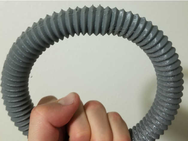
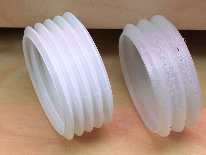

And yes, if useful and possible, the idea is to use these hoses as negative molds for metal versions of the actuator.You could simply buy conventional plastic bellow/corrugated/ribbed/scale hoses and use these as molds for this kind of muscle.
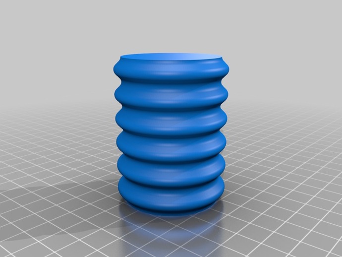
I will try to 3D model my idea later, but basically, I thought on just making a scale-hose, so to speak.
Somethign with a geometry similar to this one.
It is even easyer to make in a DIY way, I suppose: you "just" make something akin do the image by partially melting tube sections and squeezing these on other tubes.
For some reason there are hoses that work exactly like this (being expandable under pressure):

So, high strength polyester bellow coat + TPE rubber, gotcha.
... Now how do I make polyester to be ondulated like this?
On images the polyester coat seems like it is too long for the hose at its initial state.

It even looks like a small intestine lol
-------------------------------------------------------------------------------------------------------------------------------
I asked ChatGPT:
"Yes, polyester clothes are indeed made from a type of polymer. Polyester is a synthetic polymer that is often used to make fabrics and textiles for clothing. It is a type of plastic made from petroleum-derived chemicals through a process called polymerization. The polymerization process involves combining monomers (small molecules) to create long chains of polymers, which can then be processed into fibers and woven into fabrics. Polyester fabrics are known for their durability, wrinkle resistance, and resistance to shrinking and stretching.
Yes, polyester fabrics can melt when exposed to high temperatures. Polyester is a thermoplastic polymer, which means it can be melted and reshaped when heated. The exact temperature at which polyester will melt can vary depending on the specific type of polyester and its manufacturing process, but it generally melts at temperatures above 250 degrees Celsius (482 degrees Fahrenheit).
Exposing polyester fabrics to high temperatures, such as from an open flame, a hot iron, or other heat sources, can cause them to melt and potentially ignite. This is why it's important to exercise caution and follow care instructions when laundering and using polyester clothing or textiles. It's also a reason why polyester clothing is not recommended for certain high-heat environments or activities."
Well, this explains a lot, maybe making this kind of hose is that simple.
-------------------------------------------------------------------------------------------------------------------------------
Also, I forgot a detail that may or may not be useful with these muscles: braiding and/or coiling their bundle.
The only problem that I could think of is that with the increase of length and number of muscles, you may need to significantly increase the fluid flow. If you are using the idea of a single big muscle, connected by springs, then this may not be as useful.
Sorry for the low quality images, but I couldn't find better images.
The source is this link: https://www.liebertpub.com/doi/epub/10.1089/soro.2021.0040
It is pay per view and I'm not paying 51 bucks for that... (I received a free version from the people that worked on the project, it is really a stainless steel microcoil)

The above image looks kinda mettalic, I wonder if they used springs instead of fishing line to limit the expansion of the muscle strand...
This image bellow is a filament mckibben muscle, but it could be useful nevertheless.

Source: https://www.liebertpub.com/doi/10.1089/soro.2019.0022
Well, I found another link similar to the first one:

Image description from the article:
"FIGURE 2. Illustrated fabrication processes of the soft microtubule and
helical coil.
A) Soft microtubule; (1) Uncured silicone elastomer
(EcoflexTM or NuSilTM) is coated on a base plate by spin coater or film
applicator; a rod which is secured in the chuck of a power drill is coated
with a layer of uncured silicone; (2) Heating the rod while rotating to
speed up the curing progress; (3) Removing the rod to obtain the
microtubule. B) Helical coil; (1) A winding machine is used to provide
mandrel rotation while a wire guide is fed by a wire (stainless steel,
brass, or fishing line) to form the helical coil; (2) Heating the coil to
relieve its stress and stabilize its shape; (3) Removing the mandrel and
grinding both its ends to obtain the helical coil. C) Making a fishing line
coil (polyvinylidene fluoride: PVDF) with the help of a carbon fiber rod as
a mandrel, power drill, and heat gun (left panel) and the obtained fishing
line coil (right panel)"
This is orders of magnitute easier to make than the other options that I've suggested here (I think).
I don't think you would need a plate with uncured silicon, but rather "just" take a long coil that isn't touching itself in any surface, then "just" dip the coil/wire/rope on curing silicon rubber multiple times until it a thick enough layer is formed on its surface.
Like dipping chicken nuggets on sauce multiple times, lol.
Or even better: slowly passing the wire (that will be the mold, as shown in the picture) through a "U" shaped chamber full of curing silicon, adjusting the speed to the thickness of the forming layer on the surface of the wire on the other end.
Also, one could using really thin music wire and not necessarily concern themselves with the rubber, using an inner bladder like polyester.
Also, there are "liquid rubbers" such as silicon rubber, latex rubber and generic rubber that come in a liquid state (duh) that could be used to create the tubing. You can easily find these onlines as buckets of 1 to 10kg of weight or some times even more.


It is hard to tell which ones are the best for elasticity, but a general rule of thumb is to take the latex tube muscle as an example: it has 300% of strain, meaning it can elongate 3 times its initial length before snapping.
You need to ask sellers what is the elasticity of each rubber and some times they will tell you a percentage, for example, they say their rubber has "60% of elasticity", although this is not a young's modulus (elastic modulus), it can tell you that the seller is pretty sure that this rubber can elongate at least 60% of its initial length without snapping.
But like I said before, not snapping is not necessarily good parameter, because it doesn't mean the muscle will survive multiple cycles of elongating and coming back to its original shape.
-------------------------------------------------------------------------------------------------------------------------------
Well, if making hundreds or thousands of springs is not your thing, I could suggest using gas struts, or gas springs:
You would need to find a way of making a flexible gas strut and make that thingie above were you use it as a tension spring.
As convoluted as it is to use a pneumatic spring into a hydraulic actuator that works like a muscle, gas struts have constant force and don't degrade over time for being in a compressed state for long times. Unlike conventional springs and elastics, which tend to slowly tear and suffer from mechanical fatigue.
Not to mention that gas is a very abundant material to work with, unlike latex or music wire, which can be expensive and hard to make for this specific task (since you would need hundreds if not thousands of these).
So a flexible gas strut as a tension spring could be an interesting choice.
The two articles bellow don't actually explain how this flexible hydraulic cylidner would be made without inflating the whole thing due to the pressure inside of it.
You could maybe use non-elastic silicon rubber, polyurethane rubber, and/or a composite of either one of these options with some inliner material such as stainless steel, rope, polyethylene rope and so on.
In either option, you would find yourself with a flexible, but not elastic, cylinder that could be easily casted using a mold. And the mold could be made having the flexibility in mind in the first place, like having corrugated surfaces that allows for greater range of flexibility.
Although these would be hydraulic cylinders, you can turn them into a gas strut by making a hole connecting both faces of the piston head and so on.
You don't even need to make a hole through the cylinder head, just connecting the two parts would be enough.
Maybe it would be useful to use segmented/articulated hoses as the cylinder, of course, with some low-friction material as the inliner and as the outliner, so whatever part that is in contact with each other doesn't wear out that fast and/or helps minimize efficiency losses.

- https://grabcad.com/library/flexible-coolant-1
![]()
- https://grabcad.com/library/flexible-oil-coolant-pipe-1
![]()
- https://www.thingiverse.com/thing:1754888
![]()


-------------------------------------------------------------------------------------------------------------------------------
"The efficiency of a gas spring and a conventional metal spring can vary depending on several factors, including the specific design, materials used, and intended application. I can provide you with a general comparison, but please note that these values are rough estimates and can vary widely based on the factors mentioned above.
Gas Spring Efficiency: Gas springs, also known as gas struts or gas shocks, are often used to provide controlled motion and damping in various applications. They typically consist of a gas-filled cylinder with a piston and a rod. Gas springs can have relatively high efficiency due to their ability to provide controlled and adjustable force over a range of motion. In general, gas springs are more efficient than metal springs in applications that require precise control of force and motion, such as automotive suspensions, office chairs, and industrial equipment. The efficiency of a gas spring is often around 80-90%.
Conventional Metal Spring Efficiency: Conventional metal springs, such as coil springs, are widely used for their simplicity and reliability in various applications. The efficiency of a metal spring can vary based on factors like the spring design, material properties, and the intended use. Metal springs can experience energy losses due to friction between the coils and other factors. Generally, metal springs might have an efficiency ranging from 70% to 85% or more, depending on the quality of the spring design and manufacturing.
It's important to note that these efficiency estimates are rough and can be influenced by factors such as spring design, materials, surface treatments, and the specific conditions of use. Additionally, the choice between a gas spring and a metal spring will depend on the specific requirements of the application, including factors like damping control, adjustability, size constraints, and cost considerations."
-------------------------------------------------------------------------------------------------------------------------------
Also, something that I forgot to talk about last Project Log (I didn't, the text got so long it deleted itself): gaskets.
Here is a good video on how to make DIY gaskets both for the DIY Iron Air battery and hydraulic parts:
-------------------------------------------------------------------------------------------------------------------------------
Also, I totally forgot about the electromagnetic version of this muscle.
Basically, the idea of a reversibly actuated electromagnetic artificial muscle (RAEAM for short) is to use rubber bands squeezed between electromagnets in order to extend it, and once the electromagnetic force releases the pressure, it contracts.
Just like a dielectric elastomer, but using electromagnets instead of kilovolts.

One could make dielectric elastomers, but these kinds of actuators are even less efficient than conventional hydraulic artificial muscles.
And I do think I would be able to squeeze a high amount of efficiency out of this method.
However, I do think it would be even easier to mass produce this kind of actuator, specially since you wouldn't need a hydraulic pump for every fiber, resulting in a easily self-contained artificial muscle.
I don't quite remember what was my final conclusion on this subject, but I think I probably got the values wrong.
Also, bar or PSI (pounds per square inch) is a measure of pressure on the surface of something, so in order to squeeze the rubber bands, I would need a force equivalent to the pressure the rubber muscles would be suffering.
1 Bar = 1 Atm (atmosphere) = 1kgfcm² (1 kilogram force per square centimeter)
If the rubber tubes on RAHAM actuators were under a pressure similar to 5 to 6 bar, then I would need to squeeze a square centimeter of rubber band with a force equivalent to 5 to 6 kilograms of force.
The only problem with the RAEAM actuators is the lack of continuity that the dielectric ones don't suffer.
Meaning that in a unsqueezed state, the electromagnets would be closer to each other, but once the pressure is applied, they would be far apart, resulting in "islands" of pressure that could be a problem for the elastic material.

For solving this in some way, you would need to use coils as electromagnets with or without core.
Something akin to a coil stator of a syncrhonous motor where coils over lap one above another:
-------------------------------------------------------------------------------------------------------------------------------
I will try to continue this Project Log later, but basically, I'm facing yet another dilemma: which reversibly actuated hydraulic artificial muscle (RAHAM) to choose.
- Reversely Actuated Spring Hydraulic Artificial Muscle (RASHAM).
- Reversely Actuated Electromagnetic Loaded Elastic Artficial Muscles (RAELEAM).
- Reversely Actuated Strut Loaded Hydraulic Artificial Muscles (RASLHAM).
(bruh, all of these names sound like egyptian gods or something)
Each type has its own advantages, disadvantages and unique challanges/problems to deal with.
-------------------------------------------------
The problem of the first two is material price tag, since I would need kilometers and/or kilograms of elastic rubber and/or springs, which are cheap individualy, but not easy to find on bulk.
I'm trying to contact a few elastic rubber distributors to see if I can find one that is cheap enough, but I'm not optimistic about the price tag. However, I did find latex rubber bands per kg on the cheap, but I don't know if it would be worth the trouble of working with these normal rubber bands to turn then into fibers or something...
I asked to at least 3 dozens of sellers online and one said that they would sell 10kg of elastic latex rubber for exercize for 180 reais (36 dollars), which I'm skeptical that there is a misunderstanding in communication.
But in either way, if there is a problem and I receive sketchy rubber tubes, I can just ask for refund and/or help from the website admnistration.
-------------------------------------------------
The second one (RAELEAM) has its own problems too, I would need equally an absurd amount of copper wire and magnetic cores.
Well, the copper wire is already sold by kilogram and its fairly cheap, but the magnetic cores would need to be made by hand, not to mention that I would need to build a machine that builds this kind of muscle in the kilometers.
I would also need to make a cooling system since rubber and electromagnets heat up over usage (yes, rubber changes temperature during its cycles of use).
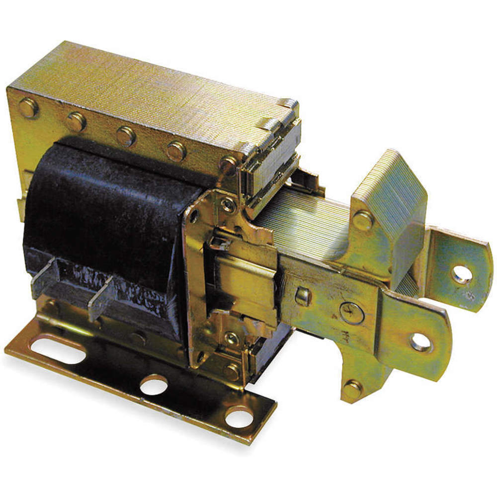
Another problem:

This is a 5 kg force solenoid.
How would I be able to miniturize this thing for a fiber?

I found this electromagnet in the pick has a 15kg lifting capacity and has 70mm of diameter and 9mm of height.
So, with that I could maybe figure out a way of scaling down the system.
Another thing that I should've thought is on instead of putting two coils facing each other, put one coil facing a plate connected to the solenoid core.
Once the core is attracted to the center of the coil, it will be squished between the two.
https://www.omnicalculator.com/physics/solenoid-magnetic-field
Accordingly to this solenoid calculator, if I were to have an 30 amp coil with 10 AWG, and a length of 5mm, I would just need 7 turns to achieve 50 tesla of electromagnetic force, which equals to 50 Newtons, which means 5 kilograms of force.
This other calculator says that I would need 1400 turns for a 1cm long solenoid with 300 amps in order to achieve 5 tesla
... Yeah, it seems like I will need to rule out the electromagnetic option. It is just too bulky, and the more amperage that I get, the hotter it gets, and the hotter it gets, the easier to simply melt the rubber off.
But the positive part is that now I know more or less how to make a propper solenoid for the solenoid hydraulic micro-pump...
... Or maybe not...
I was thinking here, maybe this "micro-pump" won't be able to be that micro, I need this crapton of copper for a single 5kg solenoid, imagine a 20kg solenoid that needs to move back and forth hundreds of times per minute?
There is a type of solenoid called "laminated solenoid", which is meant for AC systems, but this thing just bugs my head, it is meant to be high frequency moved or just stay still?
In any way, something akin to this would need to be added to every artificial muscle (I still didn't calculate how much fluid flow every muscle would need, but you get the idea).
-------------------------------------------------
The third option doesn't have the problem of availability of material and it would be the most efficient one of the bunch, but it has the problem of being extremely complex to build.
Even though I gave the idea of using an outliner and an inliner made out of teflon plastic for the lowest friction possible, I don't know how I would even make dozens or even hundreds of this actuators for a mech or even a exoskeleton.
Of course, at such point you wouldn't actually need to make/add the pneumatic spring, it would just be a conventional pulling hydraulic cylinder like any other, just flexible and not capable of applying pushing force due to it being flexible.
Well, I think here about the problem of this image: the cable doesn't bend in the same manner as the walls.
Of course, you could solve this by either creating rings to conduct the cable or just making a thick cable that will bend in the same proportion as the walls.
One other problem that this could solve is the need for telescopic actuators. You could "just" put a really long actuator strapped at its middle instead of attaching it to each point without much problem; after all, the actuators are maleable and won't block themselves during travel.
-------------------------------------------------
I asked around if it would be possible to melt latex rubber bands into other shapes, so I could solve this problem.
-------------------------------------------------------------------------------------------------------------------------------
Useful video, I believe.
I asked ChatGPT:
"Latex rubber bands are made from natural latex rubber, which has a relatively low melting point. While it is technically possible to melt latex rubber bands, it's important to note that the process may not be straightforward and could have potential safety and environmental concerns.
Latex rubber typically begins to soften and degrade at temperatures above its melting point, which is generally around 180-200°C (356-392°F). However, reaching these temperatures could release potentially harmful fumes, and the process might not result in a clean or usable melted material. Additionally, the process could produce noxious odors, and there is a risk of fire if not carefully controlled.
If you're looking to repurpose or recycle latex rubber bands, it's recommended to explore other methods such as reusing them or finding appropriate recycling facilities that can handle rubber materials.
As always, if you're considering any unconventional use of materials or attempting to alter them in any way, it's important to prioritize safety, follow proper guidelines, and be mindful of potential hazards. If you have specific intentions or goals related to melting latex rubber bands, it's a good idea to consult with experts in materials science or chemical engineering before proceeding."
The duration of heat exposure required for rubber vulcanization can vary based on factors such as the type of rubber compound, the specific vulcanization process being used, and the desired properties of the final product. Generally, the vulcanization process can take anywhere from a few minutes to several hours.
For traditional sulfur-based vulcanization, which is a common method, the process can typically take around 20 to 60 minutes at temperatures ranging from 140°C to 160°C (284°F to 320°F). However, modern vulcanization techniques, such as microwave or electron beam vulcanization, can significantly reduce the time required for vulcanization.
It's important to note that over-vulcanization or under-vulcanization can both have negative effects on the properties of the rubber, so careful control of temperature and time is crucial to achieve the desired results. The specific vulcanization parameters should be determined through experimentation and testing based on the particular rubber compound and intended application.
"The microwave vulcanization process for rubber sheets can vary widely based on factors such as the rubber compound, the specific microwave equipment being used, and the desired properties of the final product. Additionally, the thickness of the rubber sheet can influence the required vulcanization time.
Since there isn't a one-size-fits-all answer, I can provide you with a general guideline, but you will likely need to perform experimentation and testing to determine the exact microwave vulcanization time for your specific rubber sheets.
For a thin rubber sheet (1mm thick) used in a slingshot application, a starting point for microwave vulcanization might be in the range of a few minutes. You could start with a microwave power level of around 50-70% and an initial vulcanization time of 2-5 minutes. However, these are just approximate values and should be adjusted based on the results of your tests.
It's important to closely monitor the rubber sheet during the microwave vulcanization process and perform frequent checks to assess its condition. Over-vulcanization or under-vulcanization can affect the final properties of the rubber, so you'll want to find the right balance.
Always prioritize safety during experimentation, follow proper procedures for using microwaves, and be prepared to adjust your approach based on the outcomes you observe. If possible, consult with experts in rubber processing or materials science to get more specific guidance tailored to your slingshot application."
I received an answer:
https://www.ehow.co.uk/how_8420675_melt-rubber-bands.html
Basically, just spray vegetable oil on the pan and set it to low temperature (around 180º, like ChatGPT said).
But it says to use it as an "adhesive", not to reuse it like a different shape of rubber.
... Maybe I'm overthinking it...
Now I "just" need to figure out what is the ideal shape of electrogmanet to squeeze the rubber bands and then how to make a machine that produces both.
Also, it just crossed my mind that I could actually use the homemade graphene to mix up with the molten latex...
I wonder how graphene will impact latex rubber... hmmm
I was asking if it is possible to remelt latex rubber bands, but I was receiving conflicting answers, some said that I needed to devulcanize the rubber first and others said I cannot remelt the rubber because it would just decompose.
Someone said this:
"In fact, both answers say you cannot. The first answer just mentions a hypothetical operation, needed for melting, that cannot be done easily, if at all."
The question on stack exchange: https://chemistry.stackexchange.com/questions/175648/can-latex-rubber-bands-be-remelted-into-other-shapes?noredirect=1#comment372257_175648
-------------------------------------------------------------------------------------------------------------------------------
Well, if I cannot remelt rubber bands, then I need to go back to the method one of using silicon rubber for the tubing, I just don't know which silicon is the better: rigid, soft or medium.
It would be great to just buy all of the options and just test it out, the problem is: with what money?
the worst part is that I actually found a liquid latex and liquid silicone buckets and I tested their elasticity, which was actually pretty good.
Now I can't make use of any ot these...
-------------------------------------------------------------------------------------------------------------------------------
Well, I will try to calculate the parameters of the pump.
Assuming each muscle has 150mm of length and elongates to 300mm (30cm), and all of these have 12.5 mm of inner diameter and apply a force of 80 newtons (8kg), and I want to pump it up to 1/5 of a second to achieve the 30rpm speed of the limbs, I would need around 5 liters per minute of fluid flow in a single strand. Obviously, this is to fill the artificial muscles, I could diminish it to 1/3 of a second of filling speed and get 3 liters per minute.
So, assuming the working principle of the solenoid micropump is to be a piston that travels the same distance a conventional solenoid would travel, around 10mm with a force of 5kg in order to achieve 5 bar, I would need a single solenoid with 10mm of diameter to move 90 times per second. If I were to assume the travel is actually 20mm, since two solenoid coils are moving the same free piston, it would move 45 times per second. This is like, 90 cm per second (almost a meter) and 45cm per second.
ChatGPT said that a medium frequency for a solenoid valve is 50hertz (50 times per second).
In order to lift 3000kg, I would need 375 fibers.
But a solenoid micropump goes back and forth, I only said the liter per minute of a single side, so in total, a single micro pump can actually output 10 liters per minute, and thus, I would need 187.5 micro pumps.
... For a single muscle bundle.
A 5kg force solenoid has 500 grams of weight, I would need more or less the double (since each solenoid micro pump has two solenoids), this means that the total would weight 100kg.
https://www.amazon.com/YXQ-JF-1578B-Holding-Solenoid-Electromagnet/dp/B0758CHC7F?th=1
(it actually has 800)
Assuming that I have 30 bundles in total, I would have 3000kg of weight for the hydraulic pumps only....
Well... F8ck.
What a pointless endeavor...
I completly forgot to calculate the linear pump:
Well, obviously it would be a pain to make these in the hundreds, but it would still be better than to make a fricking electric turbine engine. And at this point, I'm my bar is so low that I would accept the low efficiency of soft magnetic cores.
In any case:
Assuming that the initial length is 15cm and the elongated state is 30cm, I would need to move around 0.001 liters, or 0.737 ml.
Visualization of a single milliliter:

A little drop....
Well, frick. How do I calculate this now?
Now that I think about it, I think I have made another mistake, a single solenoid pump definitely can pump this much in less than a second.
... That's why you write the entire equation when calculating stuff, Fulano...
I need time, wait.
So, let's get this properly:
1 strand needs 0.0007 liters in order to actuate, I need it to actuate in 1/5 of a second.
0.0007x5 = 0.0035 x 60 seconds = 0.21 liters per minute.
This means that a single solenoid pump that can achieve 10 liters per minute can fill up 47 strands at same time, since I have around 375 strands, I would need 8 solenoid pumps to fill up all of these.
And since there is 30 of these bundles, I would need 240 micro solenoid pumps in total (assuming that I would have the exact same amount of strands on every bundle).
But basically, I would need 12 groups of 8 5kg solenoids, giving 96 pumps in total, giving 48kg in total.
For the torso and arms, I would need 1/3 of the strands, 125 strands per muscle, and since I would need 3 solenoid pumps per group, having 18 groups in total, I would need 54 pumps, weighting 27kg, meaning that I would have 75kg of weight in total for the pumps.
Amem brothers.
Each solenoid consumes 192 watts (I would actually be activating and disactivating two different solenoids, so I don't know how it would affect the final power consumption), so I would need 28,800 watts in total, or 38.4 horsepower.
We are so back into the game, my guys.
Also, a detail:
If you are going to use the twisting/braiding of the muscle strands, you need to remember that when doing it, you're also increasing the length of the muscle, and thus, the amount of fluid it will need.
Which you will need to take into consideration so your mech/exosuit isn't underpowered.
Plus, I would advise you to roll your muscle strands with teflon tape to lower the friction.
--------------------------------------------------
This section is before I noticed I calculated the result incorrectly.
--------------------------------------------------
The only way I would be able to pump this enough air would be using a fricking turbine.

A single axial air pump can achieve a flow of 80m³/h which is 1300 liters per minute, I would need 14 of these to achieve 18k liters per minute and more 60 times this for 6 bar of pressure. Which would be 300kw.
I was looking here, 18,000 liters per minute of air flow are more or less 1200 cubic meter per hour. Which is a value normally used for industrial fans.
https://vikiwat.com/en/industrial-axial-fan-ywf4e-250s-220vac-50hz-1400m3h.html
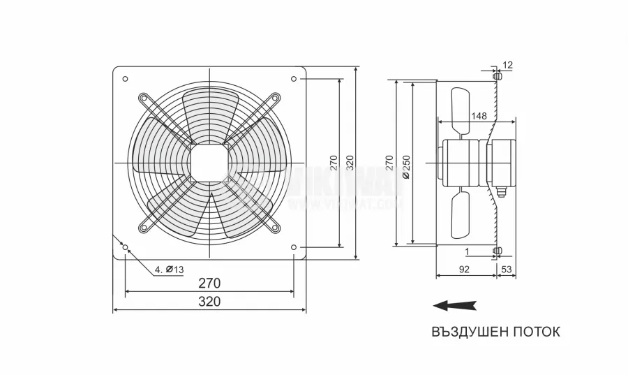
So, basically, I need a 30cm wide fan for this flow of air + a centrifugal compressor with a similar air flow.
https://sewinfla.net/products/sw-950w-air-blower

This 950 air blower has the same airflow output, but it is an axial fan, but most importantly, it has the shape of an centrifugal compressor. Meaning I could make a centrifugal compressor with same dimensions and somewhat the same flow output.
And/or maybe a multistage axial compressor.
So, 10 stage axial compressor + centrifugal compressor.
One may or may not make a turbine with such configuration in order to drive the electrical turbine.
And yes, the idea is to make a metal casting of all of this bullshit in order to achieve the proper airflow, even if this means making such frankenstein with terrible efficiency.
Not to mention that every day that passes I'm less and less confident that I will be able to make this goddamn project...
I tried to calculate and I would need more or less 150 horsepower in order to fill 12,000 liters per minute to the hydraulic muscles if it were a hydraulic piston pump, which needs way more power to be driven.
But assuming that I'm staying at 3000 rpm and a 30cm diamter axial fan, and that I would need 6 bar of pressure instead of the 9kpa, I would need 60x more torque, and thus, I would need around 25 horsepower to power this thing up.
However, since we are talking about 30% of efficiency, I would need at least 3 times this value, around 80 horsepower, or 59,656 watts.
Well, I don't know how much you should increase the torque and rpm, and how much you should increase.
But in an air compressor, I don't see why increase the torque, I believe you would only need to increase the airflow, and thus, the RPM. Maybe something around 6000rpm and 98 Nm?
... Or you could add 3 more compressors...
----------------------------------------------------------------------------------------------------------------------------------------------
Well, one thing that I forgot to talk about is the other option for the RAHAM and McKibben muscles.
One problem with the RAHAM is inherently related to its way of function: since the rubber part is the responsible for the actuation, then the force of actuating is limited by the strength of the rubber tube instead of the pressure and size of the actuator, unlike the McKibben muscle.
But a major downside of McKibben muscle is that you need braided sleeves, and braided sleeves are expensive and I can't find a 3D printed machine that could make braided sleeves on whatever size you want.
However, I completly forgot about the knitting version of McKibben muscles.
This is relevant because you can make expanding sleeves using sock knitting machines with whatever shape and/or size you want.
Source of both images:
https://www.researchgate.net/publication/334105024_Fabrication_Characterization_and_Control_of_Knit-Covered_Pneumatic_Artificial_Muscle
Apparently, the article isn't using the knit layer for the sleeve (it actualy does, page 4 and the video below), but for a conducting layer for actuation feedback loop (basically, allowing the program to detect how much it actuated).
(the video of the article)
But I remember seeing one exploring this option and working just fine, but I couldn't find it again...
But nevertheless, the images are very explanatory, you could "just" buy a knitting machine like in the image and knit around 3 kilometers worth of expanding sleeve. :|
You "just" need to tweek the 3D models in order to get a 1inch diameter expanding sleeve in order to get a McKibben muscle with 100kg of pulling force at 6 bar.
Although I don't know much about knitting and braiding, I would suppose that the diameter of the sock knitter is the equivalent to the diameter of the expanded muscle.
But you need to remember that while the muscle contracts in 20% to 40% of its length, its diameter also expands 30% to 40% or more, so you may need way more liquid, and thus fluid flow, in order to get a fast actuation.
I would also advise you to use the LDPE (low density polyethylene) inner bladder because it increases the efficiency of the muscle.

Source:
https://journals.sagepub.com/doi/10.1177/1045389X14549872
Assuming that the muscle has 1 inch of (2.54 centimeters) of inner diameter and 30cm of length, it would increase diameter in 40% and decrease length in also 40%, which would have 3.556cm of inner diameter and 18cm o
Well, the project log got so long it deleted the end ( I had to delete some stuff to fit this here, I hope I didn't delete too much [I deleted a part of ChatGPT explaining devulcanization, because it is not possible with a DIY setup]).
But basically, I wrote that with said dimensions, the artificial muscle would need 8.1 liters per minute and a single solenoid pump would be able to feed 6 of these.
But I don't know what would be its strength, so you would need to build one yourself to find out.
Also, I said that the solenoid micropump needs to be proportionally stronger accordingly to the pressure being worked with.
If it is 5bar of pressure, then 5kg of force will be applied to the 10mm solenoid pump, if it is 80 bar of pressure, then 80 of pressure will be applied to the solenoid pump.
However, I couldn't even find 10kg force solenoid, just imagine a 100kg one.

Also, I tried to calculate more or less how much force you would be able to produce with the filament mckibben muscles (I showed a pic of them more or less at the middle of the project log), and the filament above is capable of achieving 8 newtons of force and it has 10 times less inner diameter than the 300% strain RAHAM, so I would assume that a filament muscle with the same dimensions (12.5mm of inner diameter instead of 1.3) would achieve also 80 newtons of force at 4-5 bar of pressure.
In either way, I believe it will be easier to "mass-produce" it in a DIY setup way using LDPE rolls, cutting and melting it into desired shapes and adding the sleeve all in one go.
Also, I was just thinking here how stupid it is that I made 60+ project logs just to go back to artificial muscles.
Yes, I did learn a lot along the way and now I know for sure how certain things work.
But nevertheless, I can't stop thinking:
Why do I think stupid?

Me to myself every day.
Well... F8ck.
I forgot that the reversibly actuated artificial muscles (RAHAM) need to carry their own fluid (well, obviously, but my brain didn't compute this), so, it would be a problem like I previously said: the overall efficiency of the system diminishes based on its overall weight because the more weight it has to carry, the lesser its overall efficiency.
And the reversibly actuated artificial muscle (RAHAM), would need in total 0.049 liters of oil.
Well, it wouldn't be a problem if I didn't needed more than 300 of these... Per limb.
In total, there would more than 9000 muscles in total, and thus, the total weight of the system would be 551.25kg due to the hydraulic oil. If you used spacers inside the muscle, then you would need half of this value.
In the case of an exoskeleton with 100kg of carrying weight, it isn't that big of a deal, but for a 1000kg carrying capacity, it definitely is.
Since pneumatics are definitely not an option, I need to just... Deal with it. And make the final hydraulic design with that in mind, because pneumatics are really bad.
Wait, if I'm going through so much trouble trying to make a weight-efficiency in order to increase efficiency, but pneumatics are a bad option, but hydraulics are kinda useful, then why not just use dielectric elastomers? Those were 42% efficient maximum and fairly light.
The 42% is accordingly to ChatGPT, after finally being able to read the article, I noticed that actually they said it has 10% of efficien<
Discussions
Become a Hackaday.io Member
Create an account to leave a comment. Already have an account? Log In.