ElectronicABC
GERBER PCB:
https://mega.nz/file/bMRCCLbD#7ZsyZzmE5KCDRRzwyEUTtoEM9466uiZX_n_wOQmNXzI
LIBRARY COUNTTIMER:
https://mega.nz/file/6d5AxDDa#_0wIM_APF-23ApjzK1z74g2gGn9ltc5xh4AbgKfTniM
LIBRARY LIQUIDCRYSTAL I2C:
https://mega.nz/file/3EoRAA4Q#MH7MVSIId5dUemWdPqJiW7xy306gGJjQMGtHHR_cka4
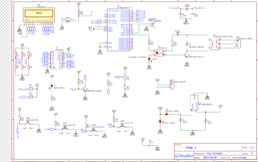
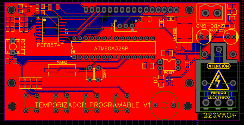
SCHEMATIC DIAGRAM
As with any project, we will first see the schematic diagram to see its connections and investigate its operation a bit.
FUNCIONAMIENTO
The operation of the system is very easy, firstly we will use ARDUINO for the creation of the code, for which we will use 2 libraries, the COUNT TIMER and the LIBRARY LIQUID CRYSTAL I2C library, taking that into account, then we will upload our code to our atmega 328p and we will start the test, we will have four buttons one for programming, another for uploading the account, another for lowering the account and finally START
This system has the autosave in the EPROM, that is to say, if we turn off the system, the final programming of the account will be saved.
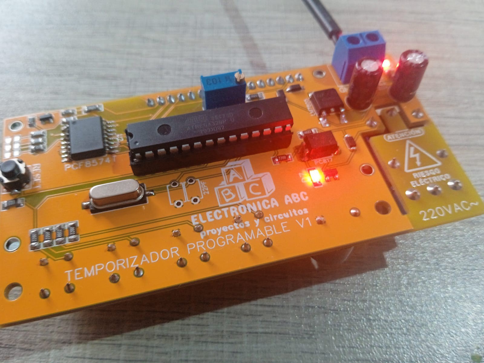
The project has an optocoupled RELAY output and will turn on any domestic device that works at 220VAC 60HZ or 110vac at 50HZ and has a buzzer that will activate once the count is finished and will notify us that the ignition time has expired and the output will turn off .
The project works at 12VDC but the microcontroller at 5VDC, so internally on the pcb it has a 5VDC regulator and it has an LCD16x2 screen to view the count.
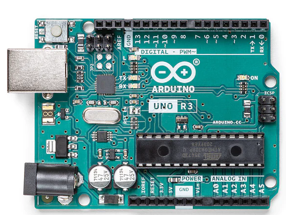
Arduino Uno
Arduino Uno is a microcontroller board based on the ATmega328P (datasheet). It has 14 digital input/output pins (of which 6 can be used as PWM outputs), 6 analog inputs, a 16 MHz ceramic resonator (CSTCE16M0V53-R0), a USB connection, a power jack, an ICSP header and a reset button. It contains everything needed to support the microcontroller; simply connect it to a computer with a USB cable or power it with a AC-to-DC adapter or battery to get started.. You can tinker with your Uno without worrying too much about doing something wrong, worst case scenario you can replace the chip for a few dollars and start over again.
"Uno" means one in Italian and was chosen to mark the release of Arduino Software (IDE) 1.0. The Uno board and version 1.0 of Arduino Software (IDE) were the reference versions of Arduino, now evolved to newer releases. The Uno board is the first in a series of USB Arduino boards, and the reference model for the Arduino platform; for an extensive list of current, past or outdated boards see the Arduino index of boards.
TEST CODE(ARDUINO)
#include   //https://github.com/fdebrabander/Arduino-LiquidCrystal-I2C-library
LiquidCrystal_I2C lcd(0x27, 16, 2);  // LCD HEX address 0x3F -- change according to yours
#include "Countimer.h" //https://github.com/inflop/Countimer
Countimer tdown;
#include <EEPROM.h>

#define bt_set    A3
#define bt_up     A2
#define bt_down   A1
#define bt_start  A0

int time_s = 0;
int time_m = 0;
int time_h = 0;

int set = 0;
int flag1=0, flag2=0;

int relay = 7;
int buzzer = 6;

void setup() {
Serial.begin (9600);

pinMode(bt_set,   INPUT_PULLUP);
pinMode(bt_up,    INPUT_PULLUP);
pinMode(bt_down,  INPUT_PULLUP);
pinMode(bt_start, INPUT_PULLUP);

pinMode(relay, OUTPUT);
pinMode(buzzer, OUTPUT);

lcd.begin();
lcd.clear();
lcd.setCursor(0,0);
lcd.print("  Temporizador   ");
lcd.setCursor(0,1);
lcd.print("Electronica ABC");
tdown.setInterval(print_time, 999);
eeprom_read();
delay(1000);
lcd.clear();
}

void print_time(){
time_s = time_s-1;
if(time_s<0){time_s=59; time_m = time_m-1;}
if(time_m<0){time_m=59; time_h = time_h-1;}
}

void tdownComplete(){Serial.print("ok");}

//tdown.stop();

void loop(){
tdown.run();

if(digitalRead (bt_set) == 0){
if(flag1==0 && flag2==0){flag1=1;
set = set+1;
if(set>3){set=0;}
delay(100);
}
}else{flag1=0;}

if(digitalRead (bt_up) == 0){
if(set==0){tdown.start(); flag2=1;}
if(set==1){time_s++;}
if(set==2){time_m++;}
if(set==3){time_h++;}
if(time_s>59){time_s=0;}
if(time_m>59){time_m=0;}
if(time_h>99){time_h=0;}
if(set>0){eeprom_write();}
delay(200);
}

if(digitalRead (bt_down) == 0){
if(set==0){tdown.stop(); flag2=0;}
if(set==1){time_s--;}
if(set==2){time_m--;}
if(set==3){time_h--;}
if(time_s<0){time_s=59;}
if(time_m<0){time_m=59;}
if(time_h<0){time_h=12;}
if(set>0){eeprom_write();}
delay(200);
}

if(digitalRead (bt_start) == 0){ flag2=1;
  eeprom_read();
  digitalWrite(relay, HIGH);
  tdown.restart();
  tdown.start();
}

lcd.setCursor(0,0);
if(set==0){lcd.print("      Timer     ");}
if(set==1){lcd.print("Prog. Timer Seg  ");}
if(set==2){lcd.print("Prog. Timer Min  ");}
if(set==3){lcd.print("Prog. Timer Hor  ");}

lcd.setCursor(4,1);
if(time_h<=9){lcd.print("0");}
lcd.print(time_h);
lcd.print(":");
if(time_m<=9){lcd.print("0");}
lcd.print(time_m);
lcd.print(":");
if(time_s<=9){lcd.print("0");}
lcd.print(time_s);
lcd.print("   ");

if(time_s==0 && time_m==0 && time_h==0 && flag2==1){flag2=0;
tdown.stop();
digitalWrite(relay, LOW);
digitalWrite(buzzer, HIGH);
delay(300);
digitalWrite(buzzer, LOW);
delay(200);
digitalWrite(buzzer, HIGH);
delay(300);
digitalWrite(buzzer, LOW);
delay(200);
digitalWrite(buzzer, HIGH);
delay(300);
digitalWrite(buzzer, LOW);
}

if(flag2==1){digitalWrite(relay, HIGH);}
else{digitalWrite(relay, LOW);}

delay(1);
}

void eeprom_write(){
EEPROM.write(1, time_s);
EEPROM.write(2, time_m);
EEPROM.write(3, time_h);
}

void eeprom_read(){
time_s =  EEPROM.read(1);
time_m =  EEPROM.read(2);
time_h =  EEPROM.read(3);
}
ELECTRONIC COMPONENTS
2 CAPACITORS 100UF25V
2 CAP 1206 100NF
4 RESISTOR 0805 1K
1 RED LED 0805
1 7805 SMD REGULATOR
2 DIODES 1N5819 SMD
1 10K PRECISION POTENTIOMETER
7 RESISTORS 1206 220ohm
3 RESISTORS 0805 4.7K
2 NPN SMD BT3904 TRANSISTORS
1 RESISTOR 1206 10K
1 PC817 OPTOCOUPLER
1 CRYSTAL 16MHZ
1 DIODE LES 1206 RED
1 DIODE 1N4148 SMD
1 PCF8574T IC
1 PUSHBUTTON 2 PINS
4 PUSHBUTTONS 4 PINS
1 LCD SCREEN 16X2
1 BUZZER
1 RELAY 12VDC
1 BLUE TERMINAL BLOCK 3 PINS
1 TERMINAL BLOCK BLUE 2 PINS
1 PCB
FEATURES
VIN 12VDC
5VDC REGULATOR
1 DIGITAL OUTPUT TO RELAY 220VAC
IMAX 220mA
PROGRAMMING BUTTONS
INCLUDING THE EPROM
PROGRAMMABLE SYSTEM
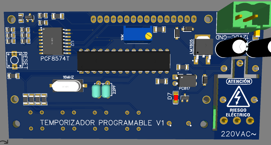
EASYEDA
Here we will see the design of the pcb both the tracks and the 3D image of how our PCB would look with the electronic components
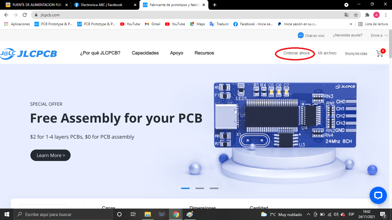
JLCPCB
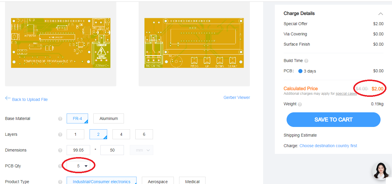
Once the pcb is designed, we will send our friends from JLCPCB to manufacture our PCB.
5pcbs only $2
JLCPCB number 1 PCB manufacturing company worldwide professional pcbs and excellent finish.
GERBER PCB:
https://mega.nz/file/bMRCCLbD#7ZsyZzmE5KCDRRzwyEUTtoEM9466uiZX_n_wOQmNXzI