 Padmalaya Rawal
You: Can we power up the Raspberry pi using Open Upcell?
We: Absolutely yes
You: How?
We: Here are the different methods you can use to power up the Raspberry pi:
To power up the raspberry pi we generally have 2 methods viz.,
1. Using GPIO
2. Using USB power supply
To power up your projects using Open Upcell, you have also 4 options viz.,
1. Using Male header
2. Using Seeed Groove (JST-PH) 4 pin connector
3. Using Stemma QT (JST-SH) 4 pin connector
4. 2 pin solder pad
So, the total number of combinations we have are as follow:
| S. No. | Open Upcell connector | Raspberry pi connector |
| 1 | Using Male header | Using GPIO |
| 2 | Using Male header | Using USB power supply |
| 3 | Using Seeed Groove (JST-PH) 4 pin connector | Using GPIO |
| 4 | Using Seeed Groove (JST-PH) 4 pin connector | Using USB power supply |
| 5 | Using Stemma QT (JST-SH) 4 pin connector | Using GPIO |
| 6 | Using Stemma QT (JST-SH) 4 pin connector | Using USB power supply |
| 7 | 2 pin solder pad | Using GPIO |
| 8 | 2 pin solder pad | Using USB power supply |
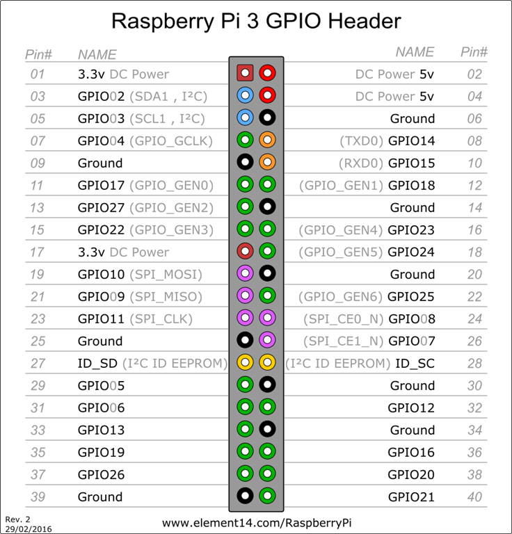
Before we go further, let's see the GPIO Pins from where we will be powering up the Raspberry pi. Please note that for this tutorial we are using Raspberry pi 3 Model B. Before powering any other please make sure that you are connecting the power to the correct pins, else you may damage you Raspberry pi permanently.
CAUTION: Please make sure that you are supplying power to the correct GPIO Pins, else you may end up damaging you Raspberry pi permanently.
Here is the GPIO pinout for Raspberry pi 3 Model B, we will use GPIO Pin 4 and 6.
You: Out of all 8 possible combination, which ones we are going to use? ALL?
We: Nope, we don't need to try all the 8 combinations
You: Why?
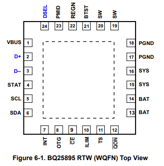
We: Because internally all the VCC pins and GND pins are connected to same pin of BQ25895 IC (brain of the board) which is PMID pin and GND pin. PMID pin is pin no. 23 and GND pin is pin no. 17 or 18 as per the IC pinout from the datasheet.
Before we continue further we expect that you have enough knowledge on how to do the initial setup for raspberry pi and have already completed that. Please connect all the peripherals such as mouse, keyboard, HDMI cable & LAN cable(optional) and if you have set it up over SSH, you are already good to go.
Method 1:
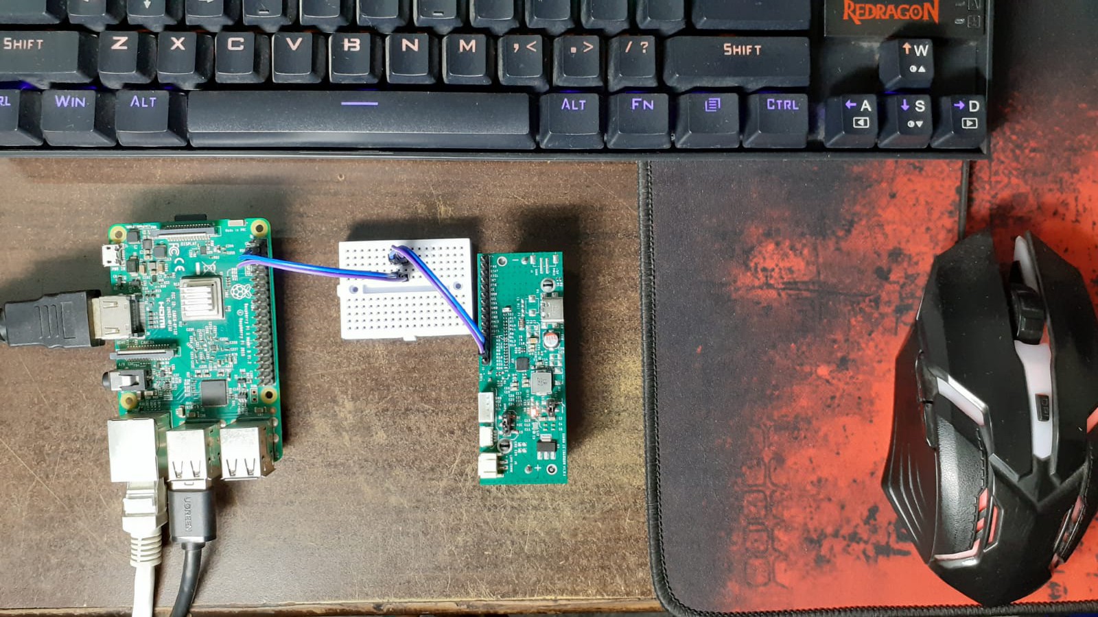
From the table mentioned above we will be connecting male header (PMID & GND) of the open Upcell to the pin 2 or 4 and 6 of the raspberry pi respectively. And here is how the setup looks.
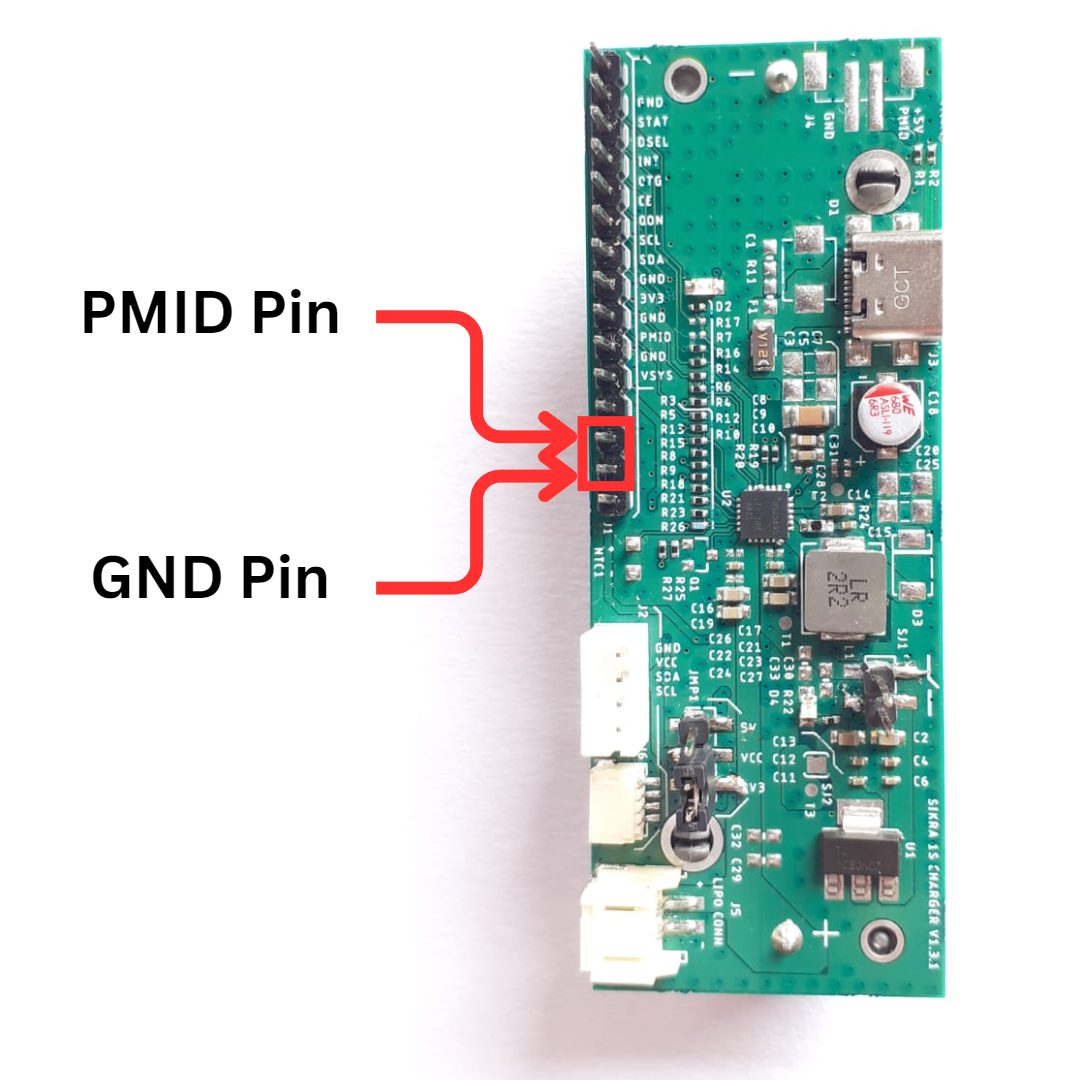
You can see the below image for the PMID pin and GND pin, pins are also indicated on the board itself as well but are little offset due to space constraints.
We booted up the Raspberry pi and boom🎆, we got a Low voltage warning as shown below
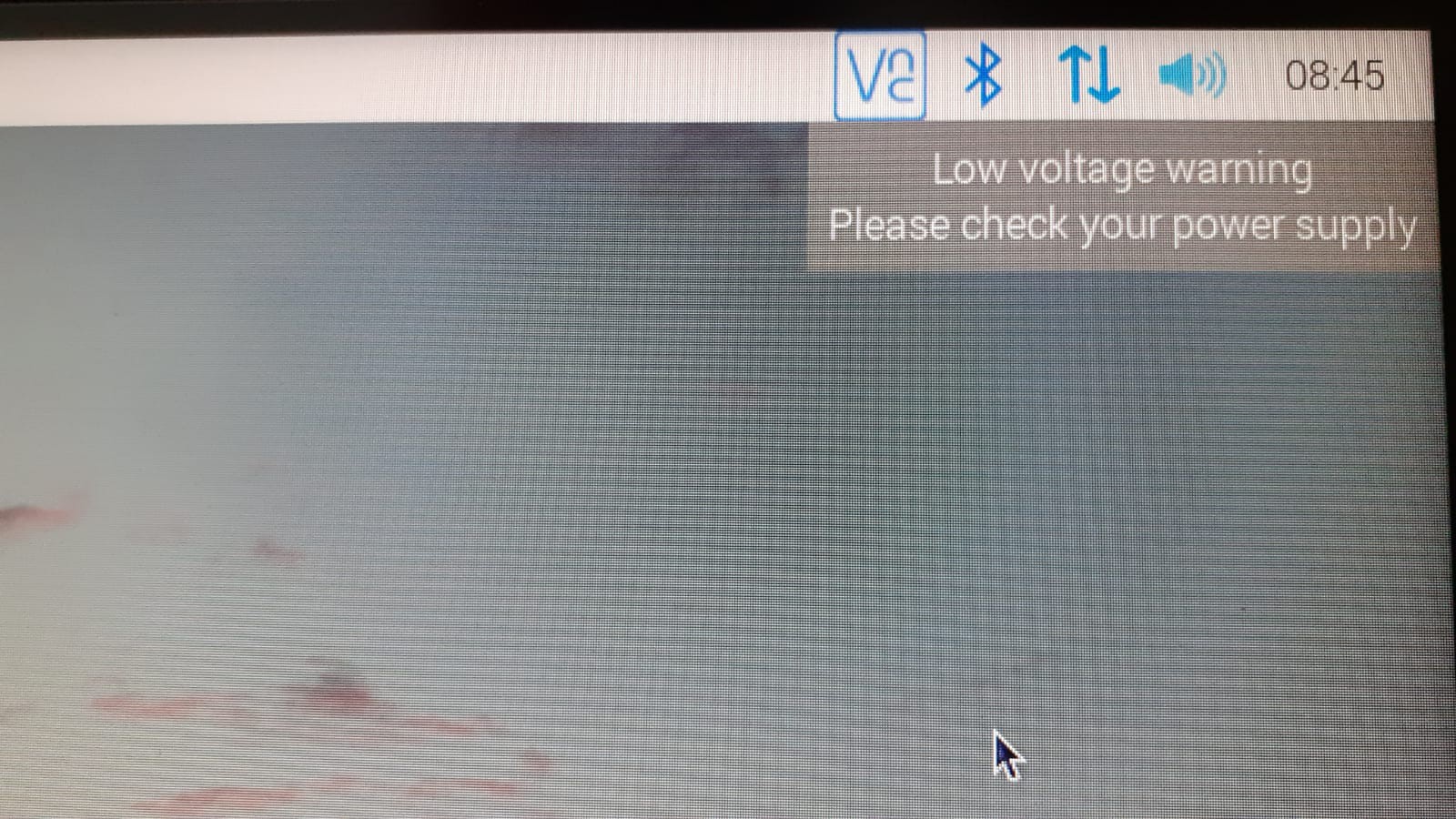
To find the culprit, I have attached the multimeter to know whether it's really a low voltage or it's a false warning because after searching a lot on the internet we found that people are getting this low voltage warning even after using a good quality and power rating adapters.
Method 2:
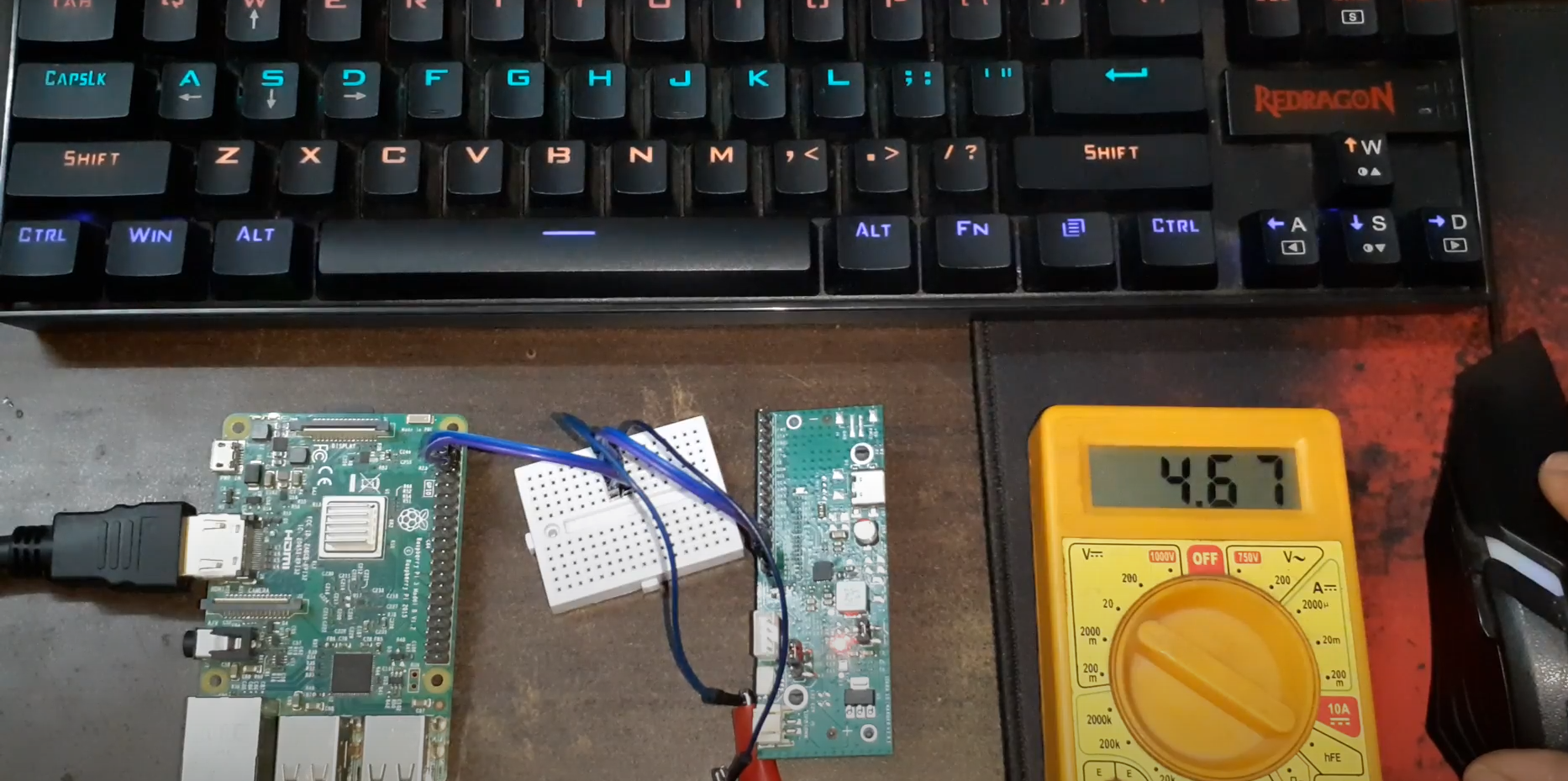
We find that it's actually the low voltage. Before we find out the reason, let's test the next combination which is using male header of Open Upcell to power up the raspberry pi over USB, for that we have made a custom connector on which one side is female USB connector and on the other side we have 2 pin male header to connect it on the breadboard. And this time we have kept the multimeter attached.
And this time again we are getting low voltage on the multimeter. But the question is why are we getting the low voltage? Wait for a while we will share the reason too.
Method 3:
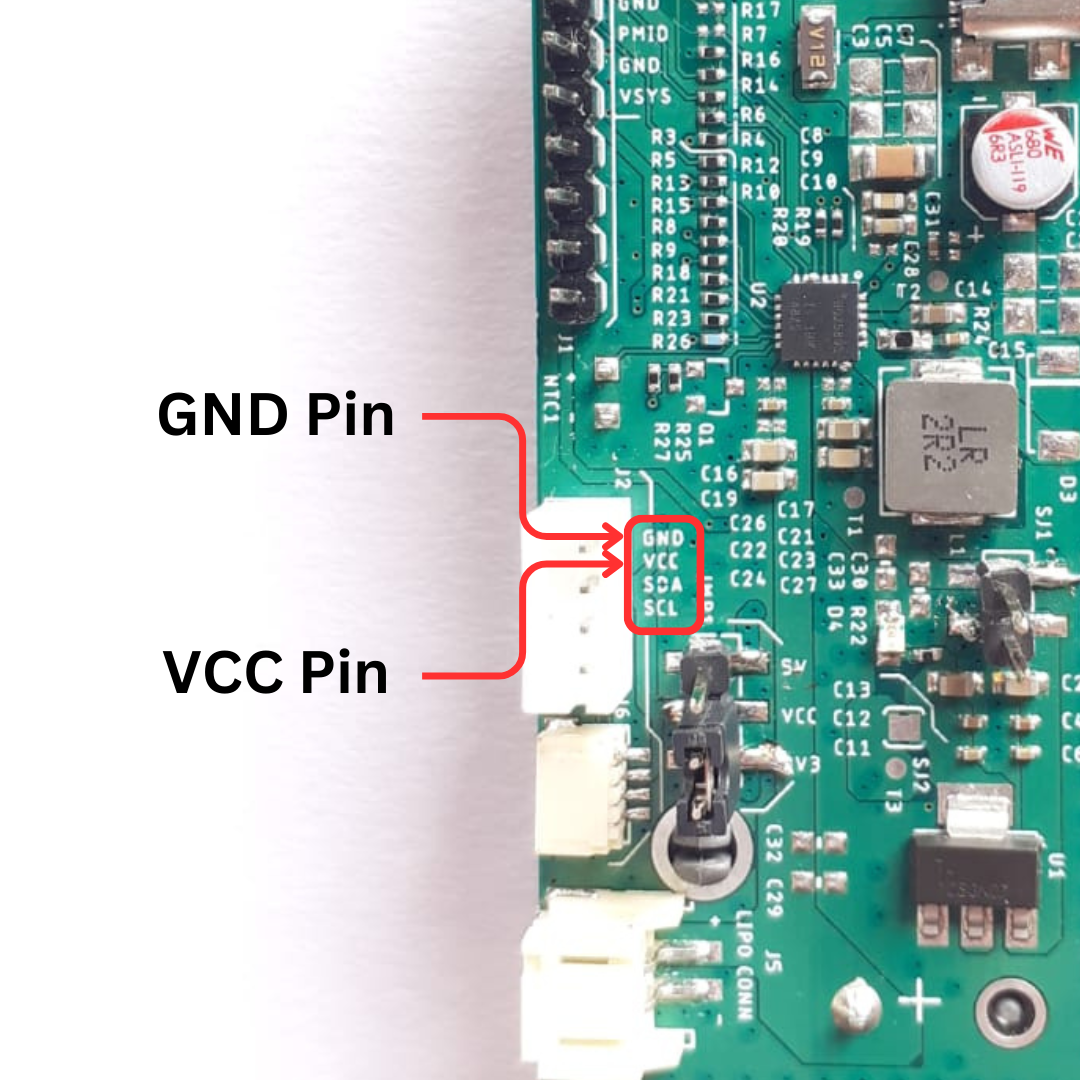
In this method we will be using a Seed studio's (JST-PH) 4 pin connector of Open Upcell and will power the Raspberry pi using GPIO pin 2 or 4 and GPI0 Pin 6. Please make sure that you are connecting the correct corresponding wire of JSP-PH connector to Raspberry pi VCC pin and GND pin. For your reference we have also mentioned the VCC pin and GND pin on the silk layer as well which can be seen in the image below:
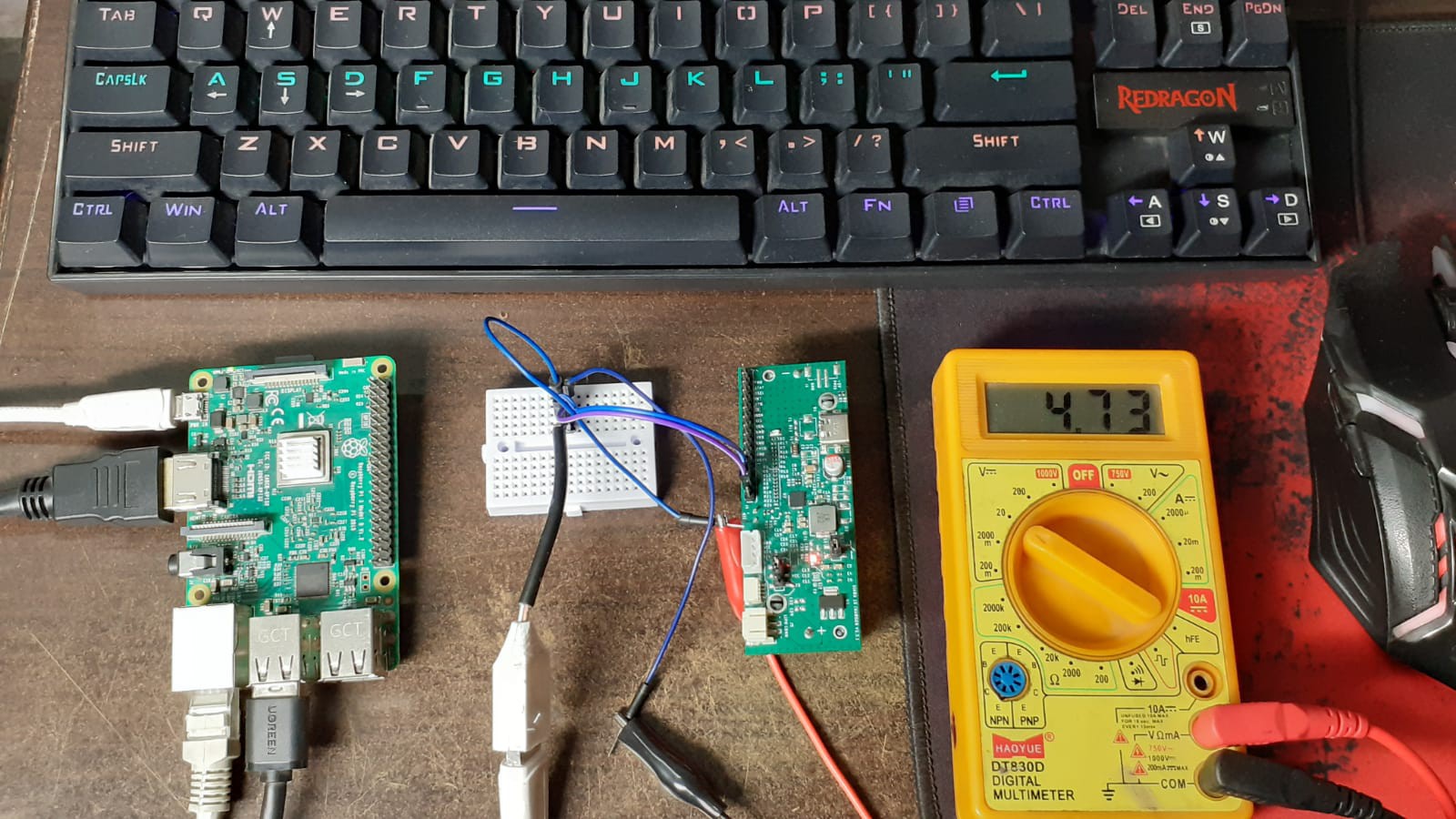
After connecting the wires as mentioned above, here is how the setup looks like and again we have still connected the multimeter to detect the voltage whether is low or not?
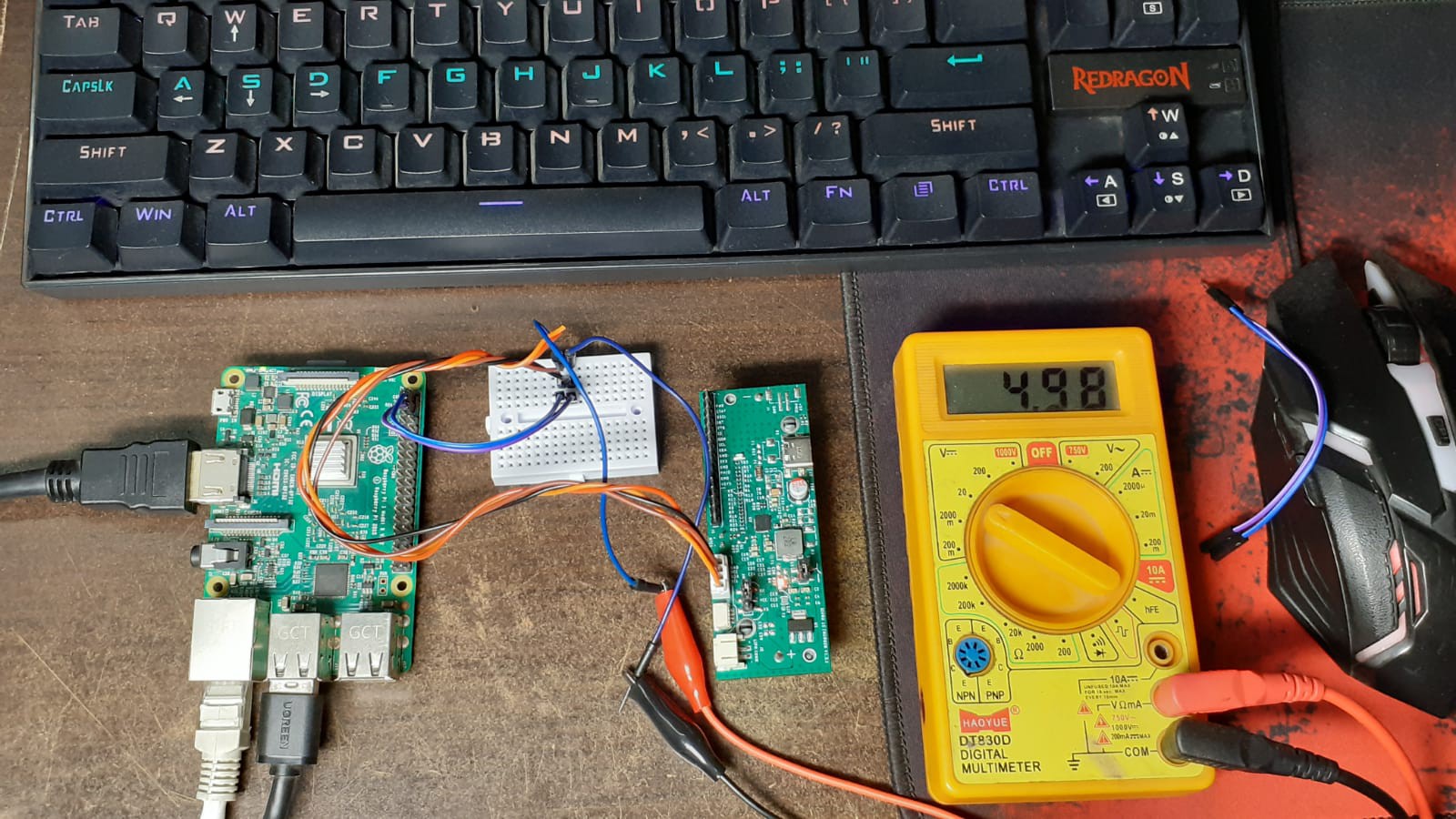
And this time, we are not getting any low voltage on the multimeter.
You: But what was the reason for low voltage in the above methods?
Me: We will discuss this after the 4th method :)
Method 4:
In this method we are going to connect the Open Upcell's JST-PH connector power pins to the USB pin of Raspberry pi using our custom made connector used in one of the previous method. And by connecting all the required wires and components, here is how our setup looks like:
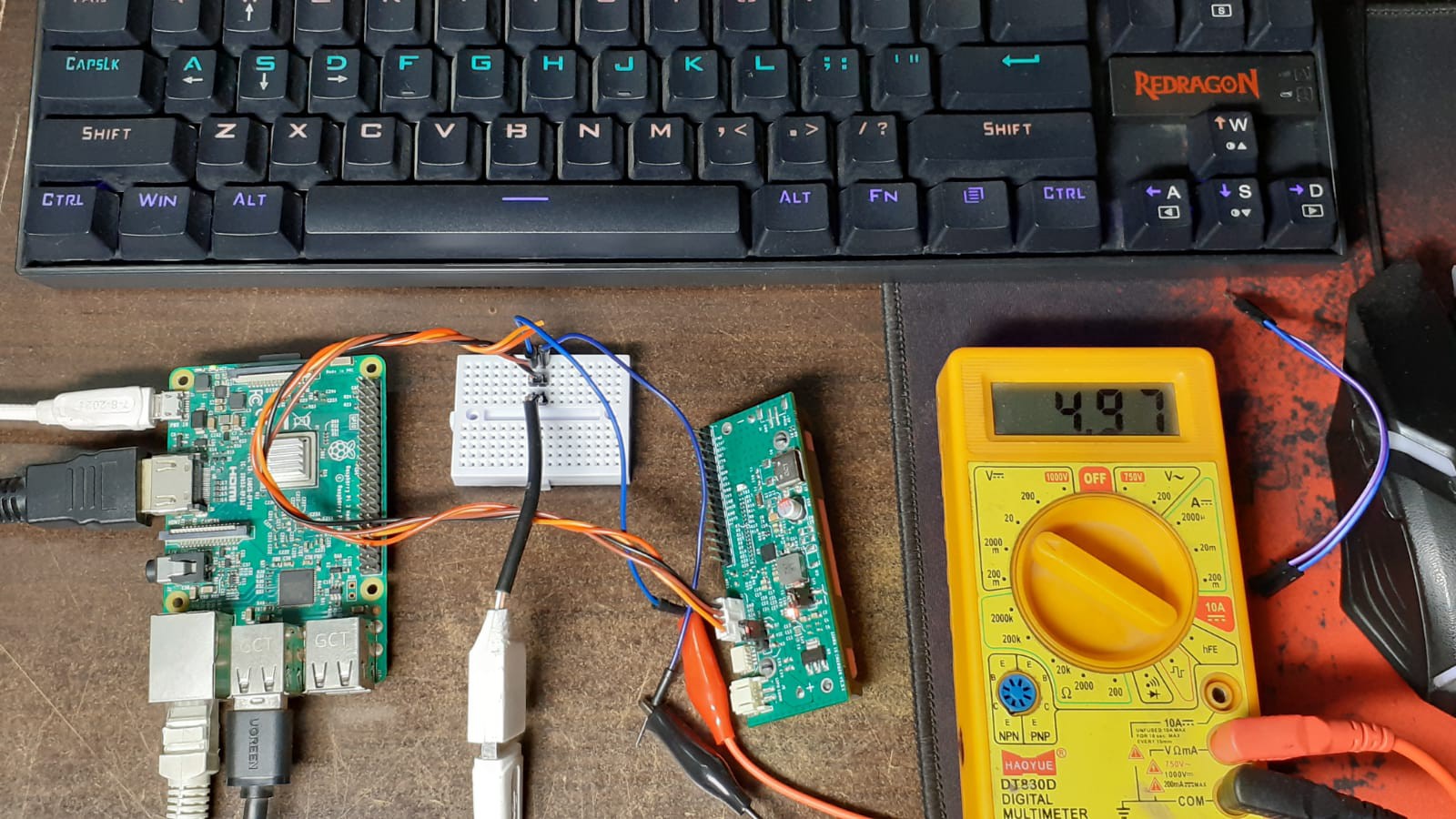
And yes again, we there is no sign of low voltage in this method as well.
But the question is why we got the low voltages in first two methods?
After tinkering and discussion with the team members we got to know that the reason for low on the line resistance of the cable which is too high (which is why its rated for 150mA) there is a voltage drop. And for any application which needs less 150mA, dupont connectors can be used and for the application where more than 150mA is required we recommend the use of Groove connector(JST-PH). To be on safer side, you can always use JST-PH connector. We have provided the dupont connector for the troubleshooting purposes and to receive the data onto to the microcontroller for further analysis.
Do you want us to try the remaining four methods? Let's us know :)
Discussions
Become a Hackaday.io Member
Create an account to leave a comment. Already have an account? Log In.