 SHAOS
SHAOSIt's already a little bit too late, but this is a fix to make frame sync work :)
--- a/PIC12-T1.ASM
+++ b/PIC12-T1.ASM
@@ -23,7 +23,7 @@ Line_:
  movwf TempN ; 1/7
 Line_loop: ; 15*3-1=44/51
  decfsz TempN,f ; (1/1)
- goto Line0loop ; (2/3)
+ goto Line_loop ; (2/3)
  nop ; 1/52

  clrf GPIO ; 1/53 -> video 48
Now image is solid: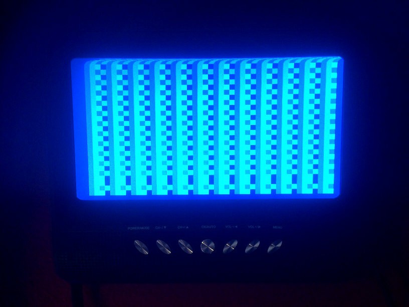
Files in the project still have version without frame sync, but GitHub is fixed
P.S. Top of the image is a little off because of GOTO at the and and CLRF in the beginning of the program - 3 extra cycles per frame that should be eliminated in future version...
ANALYSIS: As you can see it's only 4 different brightness levels, not 8 - In this version of the program GP2 is not set as output because T0CS in OPTION register has to be cleared (it's 1 by default) if we need to use GP2 as output. Also you can see 47 columns, not 48 - I'll fix it in the next version...
FIX for OPTION:
--- a/PIC12-T1.ASM
+++ b/PIC12-T1.ASM
@@ -8,8 +8,8 @@ LineN EQU 0x08 ; line counter
 TempN EQU 0x09 ; temporary counter

  movwf OSCCAL ; store factory calibration value
- movlw 7
- movwf Seven
+ movlw 0xC0
+ option
  goto loop
New screenshot with 8 shades of gray: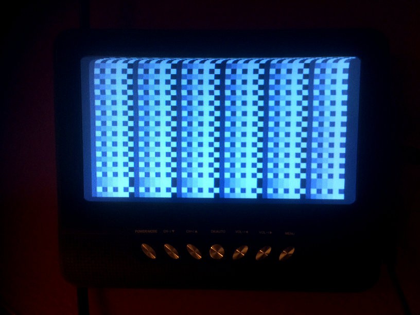
It's patterns 1,2,3,4,5,6,7,0 (incf) and 1,6,1,6,1,6,1,6 (comf)
Also I reduced pull-up resistor (from GP4 to +5V) - now it's 480 Ohm (too small?):
Discussions
Become a Hackaday.io Member
Create an account to leave a comment. Already have an account? Log In.
Nice! It makes me wonder if you use an external crystal at 3.58 MHz, can you somehow mix in some of it to make a color signal - of course you lose two pins, but maybe on a larger PIC?
Are you sure? yes | no
On faster PICs - may be, but not on this one - pixels are too wide (1MHz pixelclock)
Are you sure? yes | no
To generate color burst 3.58 MHz programmatically it has to be twice as faster pixel clock or 7.16 MHz and it means PIC must run on speed 28.64 MHz, but in order to get 16 distinguishable colors (15 actually) it has to be 57.28 MHz PIC that doesn't exist yet (at least for classic 8-bit devices).
But if we will mix 3.58 MHz from external oscillator with some logic ICs then without involving phase shift it's possible to get 4 colors - black, white, yellow (aligned with color burst) and purple (opposite to color burst - right?). So even though PIC will produce wide pixels (even wider than with 4 MHz - resolution is going to be 42x24 instead of 48x27 to keep square pixels on 16:9 screen), but those pixel might be naturally colored! And in this case we don't need 3 outputs - just 2 (to encode 4 colors) and 2 pins will be occupied by clock...
Are you sure? yes | no
Yes, I was thinking that if you ran the PIC at 3.58 MHz, you could tap the oscillator with some external circuitry and mix it in with the PIC-generated luminance data. Maybe just some analog switches (or MOSFETs) to mix in different RC phase-shifted versions of the 3.58 MHz.
Are you sure? yes | no
I'll think about it
Are you sure? yes | no
Great work !
Are you sure? yes | no
Not exactly, I used almost entire PIC12C508 just to generate this static pattern :(
Idea was to put something like a game in it, but I see now that 508 is too small for it (because of the way how I generate raster with this slow device), so I'll try to put something useful in PIC12C509 then...
Are you sure? yes | no