 Subhajit
In this IoT project, I have shown how to make an IoT-based ESP32 Alexa Home Automation system to control 1 Fan and 4 home appliances with the Amazon Alexa, IR remote. Bluetooth and manual switches.
If the internet is not available, then you can control the home appliances and fan speed from IR remote. Bluetooth and manual switches. During the article, I have shown all the steps to make this home automation system.
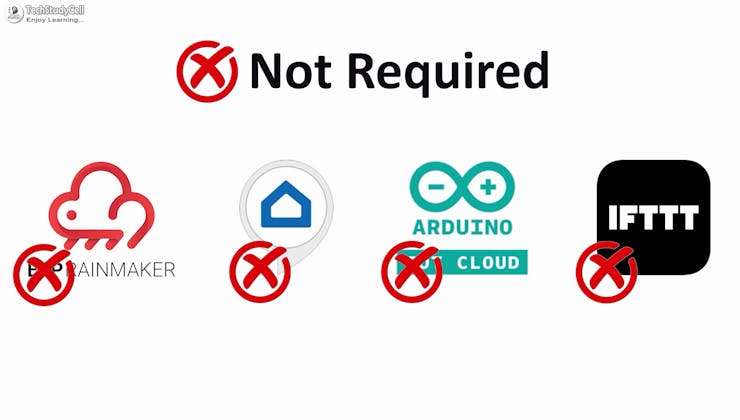
You don't need any third-party IoT applications to make this IoT project, you just need an echo device and ESP32.
During the article, I have shown all the steps to make this ESP32 home automation system.
Tutorial Video on IoT Project using ESP32 & Alexa
This Alexa ESP32 control smart relay has the following features:
- Control home appliances and fan speed with voice commands and Amazon Alexa App.
- Control ceiling fan speed and appliances with Bluetooth, IR Remote, & selector switch.
- Monitor real-time feedback in the Amazon Alexa App
- Control appliances, and fan speed without WiFi using Bluetooth App, IR Remote, & switches.
- No third-party IoT applications are required.
So, you can easily make this home automation project at home just by using an ESP32 and relay module. Or you can also use a custom-designed PCB for this project.
Required components for the ESP32 Project

Required components (Without PCB):
- ESP32 DevKIT V1
- 8-channel 5V SPDT Relay Module
- HC-05 Bluetooth module.
- TSOP1838 IR Receiver (with metallic case)
- Switches
- Any IR Remote
- 4-step Fan Regulator OR (2.2uf & 3.3uf 250V Capacitor, 2.2-ohm 1/2W Resistors, 220k 1/4W Resistors, and 4-step selector switch)
- Amazon Echo Dot
Required components (for PCB):
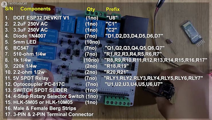
- 1. DOIT ESP32 DEVKIT V1 (1no) "U8"
- 2. 2.2uF 250V AC (1no) "C1"
- 3. 3.3uF 250V AC (1no) "C2"
- 4. Diode 1N4007 (7no) "D1, D2, D3, D4, D5, D6, D7"
- 5. 5mm LED (10no)
- 6. BC547 (7no) "Q1, Q2, Q3, Q4, Q5, Q6, Q7"
- 7. 510-ohm 1/4w (7no) "R1, R2, R3, R4, R5, R6, R7"
- 8. 1k 1/4w (10no) "R8, R9, R10, R11, R12, R13, R14, R15, R16, R17"
- 9. 220k 1/4w (2no) "R18, R19"
- 10. 2.2-ohm 1/2w (2no) "R20, R21"
- 11. 5V SPDT Relay (7no) "RLY1, RLY2, RLY3, RLY4, RLY5, RLY6, RLY7"
- 12. Optocoupler PC-817C (7no) "U1, U2, U3, U4, U5, U6, U7"
- 13. SWITCH SPDT SLIDER (1no)
- 14. 4-Step Rotary Selector Switch (1no)
- 15. HLK-5M05 or HLK-10M05 (1no)
- 16. Male & Female Berg Strips
- 17. 3-PIN & 2-PIN Terminal Connector
- 18. HC-05 Bluetooth module.
- 19. TSOP1838 IR Receiver (with metallic case)
- 20. Amazon Echo Dot
So, you can easily make this home automation project at home just by using an ESP32, HC-05, and relay module.
Or you can also use a custom-designed PCB for this project.
Circuit Diagram of the ESP32 Project
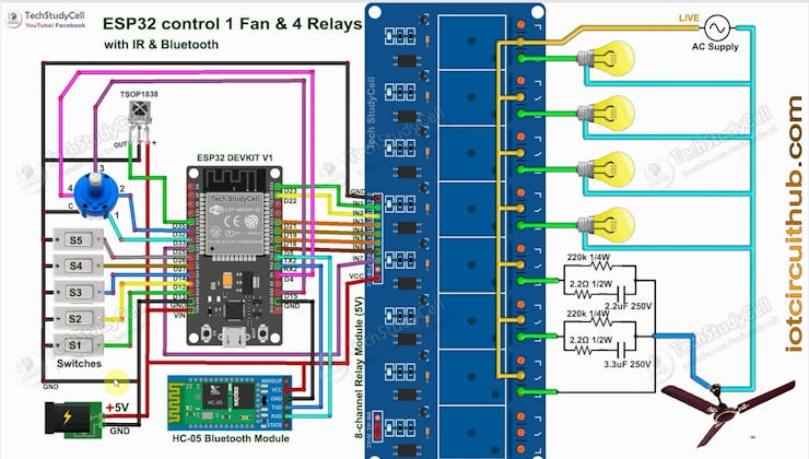
The circuit is very simple, I have used the GPIO pins D23, D22, D21 & D19 to control the 4 relays.
And the GPIO pins D13, D12, D14 & D27 are connected with switches, and GPIO D33, D32, D15 & D4 are connected with a 4-step selector switch to control the relays manually.
I used the INPUT_PULLUP function in Arduino IDE instead of the pull-up resistors.
IR remote receiver (TSOP1838) connected with D35.
The TX pin of the Bluetooth or BLE module is connected to the RX2 (GPIO16) pin of ESP32 for serial communication.
I have used a 5V mobile charger to supply the smart relay module.
Please take proper safety precautions while working with high voltage.
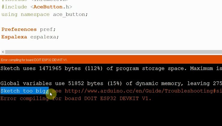
**I have not used the inbuilt Bluetooth of the ESP32, as the total size of the sketch is bigger than the ESP32 flash memory.
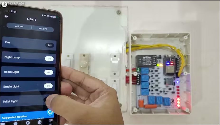
Testing the Circuit Before Designing the PCB

Before designing the PCB, I made the complete circuit using ESP32, an 8-channel relay module, HC-05, and manual switches.
As you can see, the relay can be controlled from the manual switches and Amazon Alexa App.
In the following steps, I have explained the complete projects in detail, and also shared the code and PCB Garber file.
Control Relays & Fan Speed With Voice Commands Using Alexa

You can control the relays and speed of the ceiling fan from anywhere in the world with Alexa.
If the WiFi is connected, you can also monitor the real-time feedback in the Amazon Alexa App.

The ESP32 and Amazon Echo Dot must be connected to the same WiFi network.

Control Relays With Bluetooth, IR Remote, and Manual Switch

If the WiFi is not available, you can control the relays from the Bluetooth App, IR Remote, and manual switches.
For Bluetooth control, first, you have to connect the Bluetooth App with HC-05.

To control the fan speed with the IR remote. I have used 2 buttons to increase and decrease the fan speed from the IR remote.
I have explained how to get the IR codes (HEX codes) from any remote in the following steps.

You can also use a selector switch to control the fan speed manually if the WiFi is not connected.
Please refer to the circuit diagram to connect the switches.
Design the PCB for This Home Automation System

To make the circuit compact and give it a professional look, I designed the PCB after testing all the features of the smart relay module.
GitHub link to Download PCB Gerber File
For this project, I have the JLC SMT Service while ordering the PCB.
Why you should use JLC SMT Service?
On JLCPCB's one-stop online platform, customers enjoy low-cost & high-quality & fast SMT service at an $8.00 setup fee($0.0017 per joint).
$27 New User coupon & $24 SMT coupons every month.
Visit https://jlcpcb.com
JLCPCB SMT Parts Library 200k+ in-stock components (689 Basic components and 200k+ Extended components)
Parts Pre-Order service https://support.jlcpcb.com/article/164-what-is-jlcpcb-parts-pre-order-service
Build a Personal library Inventory, save parts for now or the future
Assembly will support 10M+ parts from Digikey, mouser.
Steps to Order the PCB Assembly from JLCPCB

1. Visit https://jlcpcb.com and Sign in / Sign up.

2. Click on the QUOTE NOW button.

3. Click on the "Add your Gerber file" button. Then browse and select the Gerber file you have downloaded.
4. Set the required parameter like Quantity, PCB masking color, etc.

5. Select the Assemble side and SMT Quantity.

6. Now upload the BOM and PickAndPlace files.

7. Now confirm all the components which you want to be soldered by SMT services.
8. Click on SAVE TO CART button.
Select Shipping Address and Payment Mode

6. Type the Shipping Address.
7. Select the Shipping Method suitable for you.
8. Submit the order and proceed with the payment.
You can also track your order from the JLCPCB

My PCBs took 3 days to get manufactured and arrived within a week using the DHL delivery option.
PCBs were well-packed and the quality was really good at this affordable price.
Get the IR Codes (HEX Code) From the Remote

Now, to get the HEX codes from the remote, first, we have to connect the IR receiver output pin with GPIO D35.
And give the 5V across the VCC and GND. The IR receiver must have a metallic casing, otherwise, you may face issues.
Then follow the following steps to get the HEX codes
- Install the IRremote library in Arduino IDE
- Download the attached code, and upload it to ESP32.
- Open Serial Monitor with Baud rate 9600.
- Now, press the IR remote button.
- The respective HEX code will populate in the serial monitor.
Save all the HEX codes in a text file.
Program the ESP32 for This IoT Project

Please download the code for this IoT project.
First, you have to install the required libraries. I have shared all the links in the code.
* Download the libraries * Espalexa Library (2.7.0): https://github.com/Aircoookie/Espalexa * IRremote Library (3.6.1): https://github.com/Arduino-IRremote/Arduino-IRremote * AceButton Library (1.9.2): https://github.com/bxparks/AceButton
Then enter the WiFi credentials:
const char* ssid = "WiFi Name"; const char* password = "WiFi Password";
Then enter the Device Names for Alexa.
// device names String Device_1_Name = "Night Lamp"; String Device_2_Name = "Room Light"; String Device_3_Name = "Studio Light"; String Device_4_Name = "Toilet Light"; String Device_5_Name = "Fan";
Update the HEX codes for IR Remote Buttons
//Update the HEX code of IR Remote buttons 0x<HEX CODE>
After that select the DOIT ESP32 DEVKIT V1 board and the PORT. Then click on the upload button.
While uploading the code to ESP32, if you use the PCB then you will see the "Connecting....___" text, then press and hold the BOOT button, and after that release both buttons.
Configure the Alexa App for the Smart Home System

Open Amazon Alexa App and follow the steps:
1. Tap on Devices. Then Tap on the "+" icon.
2. Tap on "Light", then select "Others".
3. Goto Alexa and tap on "DISCOVER DEVICES".

It will take a minute to add devices. During this time the ESP32 and Echo dot must be connected to the same WiFi.
4. Tap on "Devices", and tap on "Lights" to see all the devices.
Connecting the Bluetooth App

First, download and install the Bluetooth Switch App
Download Bluetooth App from GitHub
- Then, give the Nearby Device permission to Bluetooth app so that it can search for nearby Bluetooth devices.
- Turn on the Mobile Bluetooth and pair the HC-05 Bluetooth module
- Go to Bluetooth App and tap on "Connect".
- Tap on HC-05 from the list.
- Once it is connected, you can control all the appliances and fan speed with the Bluetooth app.
I have explained all the steps during the tutorial video.
Connect the PCB With the Appliances and AC Supply

Please connect all the appliances as per the above circuit.
Please take proper safety precautions while working with high voltage.
Finally!! the Alexa Home Automation System Is Ready

Now you can control your home appliances in a smart way.
I hope you have liked this Alexa home automation project. I have shared all the required information for this project.
I will really appreciate it if you share your valuable feedback.
Also if you have any queries please write in the comment section.
Thank you & Happy Learning.