 doctek
(Here's the complete description - sorry for some redundancy.) There are many single chip bipolar stepper motor controllers. These can supply one to two amps and work great for most NEMA 17 and smaller motors. But I wanted to control a long NEMA 23 motor with 0.3 Ohm coil resistance. For comparison, a NEMA 17 with 1 Ohm resistance took over 1A from an a4988. Even NEMA 17s can cause a lot of heating! Larger motors are often controlled using the TB6600 or TB67S109. These controllers can handle 3 to 3.5A, but are a bipolar design and require large heat sinks. Trinamic offers the TMC5160A that uses external FETs and can handle 5 Amps easily. Since that's more than enough for the motors I have, that became my design goal.
There are various boards available using the TMC5160A. The TMC5160-EVAL is good for 4.7A, but costs $108. The smaller TMC5160-BOB is only good for 2.8A and costs $22. The TMC5160 SilentStepStick claims 3A and only costs $15. But the last two boards lack the necessary capacitors needed for reliable operation, and have no wiring connectors. My goal is to design a complete solution that can handle 5A safely and reliably, and not require a huge heat sink. The ease of use of the Trinamic controllers and configuration using SPI was very attractive. Although I'm currently using very few of the features, it's good to have options.
The design process is described in the data sheet, but there are a few details that are glossed over. The first one is the sizing of the gate resistors. The second is the sizing of the bulk capacitors. Software is left as an exercise for the user.
I will focus on my design and the software that worked. There was lots of experimenting and mis-steps to get here, lots of help from Joey Gross, the Maxim/Trinamic Tech Support Guy, and still lots to do. But it's time to share. The design seems to be working well enough to be useful. Perhaps what I did will inspire others to help wring out the design.
Circuit Design Details
The design shown in the data sheet provided most of the guidance for creating this board. The limitation of 24V is due to my desire to avoid excessive heat generation in the Trinamic part. Since 24V was my design goal, I'm quite happy with this. However, my first efforts at bringing it up were less than successful. Partly this was due to lack of details about the software needed to configure the device, and partly because part selection could have been improved - but not really explained in the data sheet. Both these problems were resolved with crucial help from Joey at Maxim support. The software is discussed below. The hardware design notes follow. Start with the schematic. The KiCad files and a pdf of the schematic are in the Files Section.
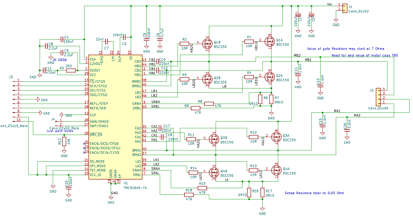
| TMC5160A | TQFP package selection | It was available! | ||
| MOSFET Selection | BSC150N03LD, 30V, 20A, 12.5mOhm RdsON, Qg 10nC | Dual Package | Would have preferred 40V, but this was available | |
| C1, C2 | Vm Bulk Smoothing Capacitors | See discussion below | ||
| C3 | Charge Pump Voltage Capacitor | 100nF, 100 V | Sec. 29.5, Schematic | |
| C4 | Analog Supply Capacitor | 100nF, 100 V | Sec. 29.5, Schematic | |
| C5 | Vm Filter Capacitor | 100nF, 100 V | Sec. 29.5, Schematic | |
| C6 | Vm Filter Capacitor | 4.7uF, 100 V | Sec. 29.5, Schematic | |
| C7 | Charge Pump Capacitor | 22nF, 100V | Sec. 2.2, Pin 32 of TQFP | |
| C8 | 12V Out Capacitor | 2.2uF, 25V | Sec. 2.2, Pin 3 of TQFP & Sec. 29.5, Schematic | With Bootstrap capacitors of 220nF, 2.2uF was right. When Boostrap Caps were raised to 470nF, 4.7uF was used. |
| C9 | 5V Out Capacitor | 2.2uF, 25V | Sec. 2.2, Pin 5 of TQFP & Sec. 29.5, Schematic | Raised to 4.7uF at suggestion of Apps Engineer. |
Hardware Design Table continued (Trying to avoid the vengeance of the Table creator.)
| C10, C12, C17, C18 | Bootstrap Capacitors | 220nF, 25V | Fig. 3.1, Note at lower right - MOSFET Qg <20nC & Sec. 29.5, Schematic | Raised to 470nF at suggestion of Apps Engineer. |
| C13, C14. C15, C16 | Bridge Output Capacitors | 1.0 nF, 100V | Fig. 3.5, Note at lower right | |
| C19 | VCC_IO Capacitor | 100nF, 16V | 3.1, Note by VCC_IO | |
| R1, R2, R4, R5, R10, R11, R13, R14 | Gate Resistors | See discussion below | ||
| R3 | VCC Filter Resistor | 2.2 Ohm | Sec. 2.2, Pin 29 of TQFP | |
| R6, R7, R16, R17 | Sense Resistor Connections | 47 Ohm | Fig. 3.1 | |
| R8, R9, R15, R18 | Sense Resistors | 2 x 0.1Ohm in parallel, 2512 SMD | Section 9, Table - Entry for 4.7A/6.6A | |
| R12 | Enable Input when LOW | 10K | Tied low in original design | Should be tied high to allow software control of Enable |
Control Lines
| SD_Mode | Sec. 2.2, Pin 21 of TQFP | Tied to VCC_IO to select Step/Dir mode |
| SPI_Mode | Sec. 2.2, Pin 22 of TQFP | Tied to VCC_IO to select SPI mode |
Bulk Smoothing Capacitor Sizing
Bulk caps are important for reliable operation and to avoid over heating. To find the equation for sizing a "smoothing filter", simply Google for "Smoothing Capacitor". The equation I used was C = I / 2 * f * Vr, where C is the bulk capacitance, I is the rms current, f is the frequency to be smoothed, and Vr is the allowed ripple. For the TMC5160A, PWM frequency is 25KHz (12 MHZ clock), Irms is 4.7A, and Vr is chosen as 0.2V. Then C = 470uF. his value is very close to the general guideline given in the Trinamic data sheet of 100uF per Amp; implying 500uF for a 5 Amp load. I selected two 270uF, 100V, low esr capacitors. In use, these capacitors do not heat up and seem to do their job well. The design is compact enough and I don't feel a need to try and make the capacitors smaller. Of course, others could easily try smaller caps and evaluate them.
Gate Resistor Sizing
I made several attempts to calculate the gate resistor sizes based on examples in a number of apps notes. (These are in the Files section.) The results were less than satisfying! A few calculations indicated that 10 Ohms was reasonable, but I couldn't get a good, crisp result. The values I selected, 10 Ohm at 0.5W, seem reasonable and agree well with values used in evaluation and demo boards. I regard these as place holders that can be easily changed if necessary. Note sizing of the gate resistors current rating is wrong. Due to low duty cycle, these don't need to be 1206, 0.5W units - 0603, 0.1W would work just fine. Experimentally, the values I have chosen work well and don't heat up in operation. Performance curves are taken from my scope and seem to agree well with the desired curves shown in the apps notes. I think there is a bit more ringing than I would like, but the board performs well.


Ch1 (yellow) high-side MOSFET gate drive pulse, Ch2 (blue) MOSFET output to motor. Scope settings: 5 Volts/div and 100 nSec/div. Trigger on Ch1.
What is really needed here is a thorough study of gate resistor sizing. It needs to include theory, but needs to be tied to practice as well. SPICE seems like the correct tool for sizing gate resistor. Models exist for many MOSFETs, but not for the TMC5160A. Even with these, there are unknowns I haven't even thought of. References say you must test, but can this be more focused and can the variables be understood more clearly? The study should include examples of various possible designs and the resulting performance curves. Until that work is done, gate resistor sizing remains as much witchcraft as science, IMHO. It's on my list of projects - maybe someday.
SPI Bus Details
Since the SPI bus is used to configure the TMC5160A, it's important to make sure it works properly and that multiple Beefy Steppers can be used together. The design criteria to insure this are detailed at the pjrc (of Teensy fame) web site. https://www.pjrc.com/better-spi-bus-design-in-3-steps/ Let's have a look at these and see if we're good.
First, all SPI chip select lines need pull-up resistors. This should be a 10K resistor to VCC_IO on the /CS line. This is not on the Beefy Stepper board, but can be added easily to the Arduino lbeing used (Teensy 3.2 in this case. I will add the pull-up in the next revision.
Second, the DIN (nee' MISO) line must tristate when the SPI is not selected. I verified that the TMC5160A behaves properly using the method described on the pjrc site.
Third, protect SPI bus access using transactions in the library. After a bit of digging through layers of doxygen, I was able to verify that the library uses transctions for SPI access.
Board layout
The example shown in the data sheet for the Eval board guided my layout - mostly. The main change was the use of dual MOSFETs. The interface to a Trinamic control board was dumped in favor of an Arduino interface with just the necessary control pins. The most important guidance I followed was the design of the high-current paths. I spent a lot of time making sure these were short, broad, and direct! I believe the results (see below) justify the effort. A four layer board is used with the inner layers being power and ground, with a few extra traces on the power layer. This provides more area for heat dissipation as well as reducing noise on the traces. Note that the KiCad design files have the enable line pulled low - it should be pulled high. Also note part changes as well (discussed above). C8 & C9 became 0805 size instead of 0603. They fit, but really should have the correct footprint.
The best way to view the board design is to use the Gerber viewer in KiCad. The Gerber files are in the Files section.
Costs
| PCB (OSHPark) | $10 each |
| TMC5620A | $9 |
| FETs | $4 |
| Bulk Caps | $7 |
| Connectors | $3 |
| Other Rs&Cs | $3 |
| Total: | $36 |
Parts are from Digikey. Remove bulk caps and connectors and you save $10. This makes the cost about the same as the cheap TMC5160A boards. Personally, I think the extra money is well worth it for a complete solution. And it's still 1/3 the cost of the expensive eval board - but a lot smaller.
Software
This board was a challenge to bring up since I had nothing to compare it to, or copy from, so I had no idea what to expect or watch out for. The data sheet seems helpful, but doesn't go into troubleshooting at all. Since all initialization of the TMC5160A is done by SPI, my first step was to try talking to the TMC5160A using the SPI bus. Following the data sheet, I tried to read the 0x04 register. This worked right away once I corrected the part placement errors which were due to a bad placement diagram. Then I tried the examples in the data sheet with no luck. I found a little sample code on the web, but it was no better. Fortunately, the Apps Engineer, Joey, clued me into the importance of the GSTAT register. (Remember Joey? I mentioned him above.) In my experience, the key is to use the GSTAT register. Write to it to reset it and verify it is clear. Not much was required to make the motor go after that, but lots more experimentation is possible to make use of more features. My main goal was to control a higher current motor; the other stuff can wait. I suspect the reason that other examples did not work is likely because they ignored the GSTAT register.
The best library for the TMC5160A that I found was the TMCStepper Library. While it seems to support all functions of the TMC5160A, it is yet another powerful library with essentially no instructions on how to use it. (I'm sorry, but doxygen output provides only the barest hints.) One must search through the library code to find function names, call patterns, etc. Even the initialization code is hard to find! Fortunately, I found an example on the web that provided just enough guidance.
In passing, I want to note that doxygen can produce great documentation with some effort! An excellent example is the NRF24 network library. Have a look at it to see just how good documentation using doxygen can be!
Arduino Program Description
This is written for Teensy 3.1 or 3.2. Other Arduino versions should work as well, but the step rate may have to be adjusted. Open T31_TMC5160_Test_AccelStepper2.ino in the Arduino IDE. Follow along as I reference the line numbers.
Lines 1-12 Here are the links to the original code that I modified. You can get the TMCStepper Library from the Arduino Library manager.
Lines 14-16 These are the required libraries. The Arduino Library manager can help you get these.
Lines 20-21 I've added a push button to start/stop the program and an led to signal the state.
Lines 23-26 This is how I connected the Beefy Stepper to my Teensy.
Lines 29-34 R_SENSE is used by the library to set the current sensing resistor value. The 0.05 Ohm value is correct for the Beefy Stepper.
Lines 37-38 Instantiate the motor driver objects.
Lines 39-43 For the state machine.
Lines 50-56 Configure pins.
Lines 59-61 AccelStepper setup.
Lines 65-68 Initialize serial and SPI ports.
Lines 70-72 TMC5160A configuration. These 3 lines I just copied. I haven't tried changing them.
Line 74 This sets the microsteps used. Values of 1, 2, 4, 8, 16, 32, 64, 128, or 256 are possible. Balance fine resolution with speed and response.
Lines 75-78 GSTAT is a key status from the TMC5160A. If GSTAT is not 0, your motor will not run! Only the first three bits are used. To clear any bit, a one must be written to it. I simply print GSTAT before and after writing 0x07 to it. It should read back as zero after doing this.
Line 79 Set the maximum desired output current. I use 5 Amps in this example, but lower values can be set.
Line 80 Driver strength relates to the current used to drive the MOSFET gates. Values of 0, 1, 2, or 3 are allowed. The data sheet says to use the lowest value that gives good results. BeefyStepper is fine with 0.
Line 81 Filt_isense can be used to reduce ringing, I think. It's not real clearly defined in the data sheet. I tried varying this, but I didn't see any difference. Value 0 is the default.
Lines 83-86 Turn on the LED, enable the TMC5160A, and set the initial state to RUN.
Lines 91-126 Check for a button press. If pressed and the state was RUN, then stop the motor. If the state was not RUN, then start the motor. The signalLED is used to signal the state and the EN_PIN controls the state of the driver outputs.
Lines 123-166 State machine to reverse the motor at the end of the desired movement. Will also hold the motor in the STOPPED state. Note the code (commented out) to report status every second. This works for about the first ten seconds, then stops. I have no idea why. I've used this with other stepper motor drivers and the AccelStepper library and it works fine. It's a mystery to me. Fortunately it's not critical - the motor runs just fine.
Results
I hear you asking, "So can this thing really control bigger motors? If so, is heat a problem?" Have a look at the test results.
Below you see the test setup. On the right is my scope probe next to the Beefy Stepper which is controlled by a Teensy 3.2. Then comes the NEMA 23 stepper with a thermocouple taped to it. The DMM monitors the temperature. In the back is the power supply to the Beefy Stepper showing current and voltage. You'll see these in action in the video below.
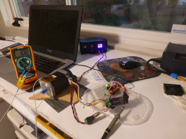
For comparison, below is a NEMA 17 stepper next to the NEMA 23 stepper.

Have a look at this movie showing the Beefy Stepper running the NEMA 23 stepper. A Teensy 3.2 does the configuration via SPI and sends step and direction signals. It runs the program I described above. You can see it operating at almost 24 volts and drawing up to 5 Amps as the speed ramps up and down. The temperature monitoring thermocouple is taped to the motor. The motor heats up to 116 degrees F. I planned to hook the thermocouple to the board as well, but it never got over 85F - I could easily hold my finger on it. Pretty boring - but also great performance. Money spent on the 4 layer board seems to have been well-spent!
Conclusion
Compare the Beefy Stepper design using the Trinamic TMC5160A to the TB6600 or TB67S109 designs. Beefy needs no external heat sink and will deliver an honest 5 Amps to drive large stepper motors. Configuration is done with software, not board jumpering. The Trinamic controller offers many capabilities not found in other stepper controllers which could be explored further using this design.
Compared to other available designs using the TMC5160A, the Beefy Stepper costs less than half as much as the only one delivering close to 5A. It delivers significantly more current than the cheaper ones and includes the bulk capacitors and wiring connectors that the cheap ones leave off. I'm quite pleased with the results the design achieved.
Please note that I do not offer these boards for sale. All information needed to build one is in the Files section and is revealed herein. I will gladly answer questions to help others.